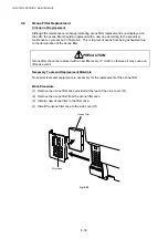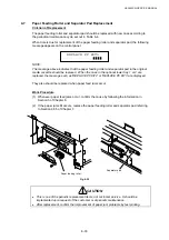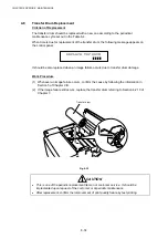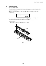
background image

CHAPTER 7 DISASSEMBLY & RE-ASSEMBLY 

7-6 

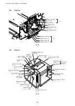
2. PARTS 

NAME 

 2.1 

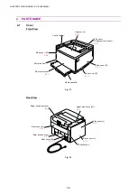
Cover 

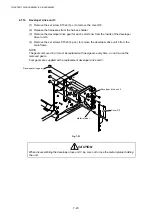
Front View 


Fig. 7-1 


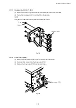
Rear View 

Fig. 7-2 

Control panel 

Upper cover  

4.2.5


Top cover 
(Paper exit unit cover) 

4.4.2


Power button 

Front outer cover

4.5.1

Media cassette 

Base cover (R) 

4.1.2


Side cover (R) 

4.1.1


Paper exit upper cover 

4.4.2


Upper side cover (LU)  

4.2.1


Side cover (L) 

4.2.3


Controller box 

Base cover (L) 

4.2.4


Rear cover (U) 

4.4.1


Rear access cover 

 4.6.1


Rear cover (R) 

4.3.7


Side cover (LF) 

4.2.6 

Summary of Contents for HL-3450CN Series

Page 1: ...Laser Printer SERVICE MANUAL MODEL HL 3450CN Read this manual thoroughly before commencing any maintenance work Keep this manual in a convenient place for quick and easy reference at all times January 2002 SM PRN028 ...

Page 2: ...stered in the United States and other countries and True Type is a trademark of Apple computer Inc Epson is a registered trademark and FX 80 and FX 850 are trademarks of Seiko Epson Corporation Hewlett Packard is a registered trademark and HP Laser Jet is a trademark of Hewlett Packard Company IBM IBM PC and Proprinter are registered trademarks of International Business Machines Corporation Micros...

Page 3: ...em and the electrical circuits and their timing information CHAPTER 5 CONTROL PANEL OPERATION Operation and setting procedures on the control panel CHAPTER 6 PERIODIC MAINTENANCE Description of periodic maintenance parts and procedures for periodic replacement and cleaning CHAPTER 7 DISASSEMBLY Procedures for replacement of the mechanical system parts CHAPTER 8 TROUBLESHOOTING Description of error...

Page 4: ...2 3 Electrical and Mechanical 2 5 2 4 Paper 2 6 2 5 Printing Area 2 8 3 ENVIRONMENTAL CONDITIONS 2 11 3 1 Ambient Temperature Humidity Altitude 2 11 CHAPTER 3 INSTALLATION 3 3 1 CONDITIONS REQUIRED FOR INSTALLATION 3 3 1 1 Environmental Conditions 3 3 1 2 Basic Layout of Printer Set up Location 3 3 2 UNPACKING 3 5 2 1 Unpacking the Printer 3 5 2 2 Unpack the Starter Kit 3 7 3 INSTALLATION WORK 3 8...

Page 5: ...r Supply Unit 4 63 2 6 Connection Diagram 4 65 CHAPTER 5 CONTROL PANEL OPERATION 5 3 1 PANEL LAYOUT 5 3 2 VIDEO CONTROLLER MODE 5 4 2 1 Configuration of Operational Mode 5 4 2 2 Line Test Mode 5 5 2 3 DRAM Test Mode 5 9 2 4 Test Print Mode 5 10 2 5 NVRAM Reset Mode 5 10 3 ENGINE CONTROLLER MODE 5 11 3 1 Configuration of Operational Mode 5 11 3 2 Operation of Normal Mode 5 13 3 3 Service Mode 5 20 ...

Page 6: ... 4 5 Drum Cleaner Replacement 6 30 4 6 Ozone Filter Replacement 6 32 4 7 Paper Feeding Roller and Separator Pad Replacement 6 33 4 8 Transfer Drum Replacement 6 34 4 9 Oil Pad Replacement 6 35 CHAPTER 7 DISASSEMBLY RE ASSEMBLY 7 4 1 BEFORE STARTING DISASSEMBLY 7 4 1 1 Precautions 7 4 1 2 Preparation of Disassembly 7 4 2 PARTS NAME 7 6 2 1 Cover 7 6 2 2 Circuit Boards PWBs 7 7 2 3 Motor Units 7 7 2...

Page 7: ...oller Mode 8 8 3 PAPER TRANSPORT ERROR 8 10 3 1 Feed Jam 8 10 3 2 Inner Jam 8 11 3 3 Outer Jam 8 13 3 4 Others 8 13 4 SERVICE CALL 8 14 4 1 Video Controller Mode 8 15 4 2 Engine Controller Mode 8 18 5 IMAGE FAILURE 8 47 APPENDIX 1 A 1 APPENDIX 2 A 6 APPENDIX 3 A 7 APPENDIX 4 A 8 APPENDIX 5 A 11 APPENDIX 6 A 14 APPENDIX 7 A 21 APPENDIX 8 A 36 APPENDIX 9 A 38 ...

Page 8: ...xternal covers the laser beam cannot escape from the machine during any phase of user operation FDA REGULATIONS FOR 110 120 V MODEL ONLY U S Food and Drug Administration FDA has implemented regulations for laser products manufactured on and after August 2 1976 Compliance is mandatory for products marketed in the United States One of the following labels on the back of the printer indicates complia...

Page 9: ... 5mW 780nm 800nm DANGER INVISIBLE LASER RADIATION WHEN OPEN AVOID DIRECT EXPOSURE TO BEAM VORSICHT UNSICHTBARE LASERSTRAHLUNG WENN ABDECKUNG GEÖFFNET UND SICHERHEITSVERRIEGELUNG ÜBERBRÜCKT NICHT DEM STRAHL AUSSETZEN DANGER RAYON LASER INVISIBLE LORS DE L OUVER TURE EVITER L EXPOSITION DIRECTE PELIGRO RADIACION LASER INVISIBLE AL ABRIR EVITAR LA EXPOSICION DIRECTA AL HAZ MAS For Finland and Sweden ...

Page 10: ...nderstanding Signal Words DANGER is used to indicate the presence of a hazard which will cause severe human injuries or a fatal accident if the warning is ignored WARNING is used to indicate the presence of a hazard or unsafe practices which may cause severe human injuries or a fatal accident if the warning is ignored CAUTION is used to indicate the presence of a hazard or unsafe practices which m...

Page 11: ...sted ozone This filter must be replaced with a new filter periodically in accordance with the manual supplied with the printer WARNING HOT SURFACE The Fusing Unit reaches a temperature of approx 160 C and adjacent parts are also very hot When you need to change the cleaning pad or remove jammed paper wait about 20 minutes after opening the paper exit unit to allow the unit to cool down CAUTION ROT...

Page 12: ...h a 3 pronged plug bi polar plug with grounding for the user s safety Use these power cords in conjunction with a properly grounded electrical outlet to avoid an electrical shock CAUTION SAFETY INTERLOCK The front cover paper exit unit and transfer unit of this printer have electrical safety interlocks to turn the power off whenever they are opened Do not attempt to circumvent these safety interlo...

Page 13: ...N SERVICE MANUAL xi CAUTION Do not lean against or apply any excessive force to the paper cassette open cover of Duplex unit Otherwise it may cause the product to decline or fall down and result in the injuries ...

Page 14: ...aution Label 5mW 780nm 800nm DANGER INVISIBLE LASER RADIATION WHEN OPEN AVOID DIRECT EXPOSURE TO BEAM VORSICHT UNSICHTBARE LASERSTRAHLUNG WENN ABDECKUNG GEÖFFNET UND SICHERHEITSVERRIEGELUNG ÜBERBRÜCKT NICHT DEM STRAHL AUSSETZEN DANGER RAYON LASER INVISIBLE LORS DE L OUVER TURE EVITER L EXPOSITION DIRECTE PELIGRO RADIACION LASER INVISIBLE AL ABRIR EVITAR LA EXPOSICION DIRECTA AL HAZ MAS 1 2 4 3 5 ...

Page 15: ...HL 3450CN SERVICE MANUAL xiii 3 Rating Label For US For Europe 4 Operation Label 5 Jam Label ...

Page 16: ... CAUTION N When shipping the printer remove the toner cartridges the OPC belt cartridge and the waste toner pack from the printer to prevent toner spill in the printer or damage of the toner cartridge and the OPC belt cartridge N When shipping the printer remove the oil bottle and the fuser cleaner from the fusing unit After removing the oil bottle be sure to remove the oil remaining in the fusing...

Page 17: ...HL 3450CN SERVICE MANUAL CHAPTER 1 PRODUCT OUTLINE ...

Page 18: ...CT OUTLINE 1 2 CONTENTS CHAPTER 1 PRODUCT OUTLINE 1 3 1 FEATURES 1 3 2 PARTS NAMES FUNCTIONS 1 6 3 INTERNAL STRUCTURE 1 8 4 DESCRIPTION OF CONTROL PANEL 1 9 4 1 Video Controller Mode 1 9 4 2 Engine Controller Mode 1 9 ...

Page 19: ... and BR Script 3 emulations producing nearly photographic quality This mode is effective when printing photographic images Maintenance Free Economical Toner Cartridge A toner cartridge can print up to 14 000 Black and 8 500 Cyan Magenta and Yellow single sided pages at 5 coverage The one piece easy to replace toner cartridges do not require difficult maintenance Universal Media Cassette This print...

Page 20: ...hics and more fonts without additional memory Various Fonts The printer has 66 scalable and 12 bitmapped fonts The fonts that can be used will vary according to the selected emulation mode In PCL mode you can also print the 13 kinds of bar codes listed below In BR Script mode the printer has 165 scalable fonts Bar Code Printing This printer can print the following 13 types of bar codes x Code 39 x...

Page 21: ...trol panel or the browser When the private print driver is selected Secure Printing can be executed which allows you to print only when a password is entered Saving User Settings It is possible to operate the printer differently from other users with the panel button settings One set of user settings can be stored PANTONE Calibrated There are many variables in process reproduction of colors genera...

Page 22: ... 2 PARTS NAMES FUNCTIONS Front View Fig 1 1 Rear View Fig 1 2 4 Top cover Paper Exit Unit 5 Power button 2 Control panel 1 Upper cover 3 Front cover Media cassette Paper exit unit 6 Power inlet 8 Controller box 7 Rear access cover ...

Page 23: ...r waste toner pack 4 Top cover Paper exit unit To exit the printed paper onto the upper cover acting also as part of the paper tray for printed paper To be opened when replacing an OPC belt cartridge or Drum cleaner 5 Power button To operate power on and off to the printer Push for On Off operation 6 Power inlet To connect a power supply cable 7 Rear access cover To act as a rear enclosure opened ...

Page 24: ...ansfer drum to the paper 6 Transfer Drum Forms color images combining the toner images from the OPC belt on the drum 7 Paper Discharger Emits a corona charge for separating the paper from the transfer drum 8 Transfer Roller Transfers the toner image on the transfer drum to the paper 9 Media Cassette Feeds paper automatically 10 Paper Pick up Roller Feeds paper automatically from the media cassette...

Page 25: ...e Video Controller Mode when the power is turned on by pressing the power button The Video Controller Mode supplies the general test printing and setting functions and some of the maintenance operations If further engine settings are required use the Engine Controller Mode 4 2 Engine Controller Mode The printer goes into the Engine Controller Mode when power is turned on by pressing the power butt...

Page 26: ...rint Secure Print Set K C M Y 1 9 4 10 13 12 6 5 2 3 11 7 8 Fig 1 4 No LED Button Name 1 LCD 16 character by 2 lines 2 Power LED 3 Ready LED 4 Data LED 5 Go button 6 Job Cancel button 7 Alarm LED 8 Secure Print button 9 button 10 button 11 Reprint button 12 Back button 13 Set button ...

Page 27: ...HL 3450CN SERVICE MANUAL CHAPTER 2 SPECIFICATIONS ...

Page 28: ... 2 4 2 2 Functions 2 4 2 3 Electrical and Mechanical 2 5 2 4 Paper 2 6 2 4 1 Printable media 2 6 2 4 2 Media cassette capacity 2 8 2 4 3 Printed output 2 8 2 5 Printing Area 2 8 2 5 1 Effective printable area 2 8 2 5 2 Print guarantee area 2 10 3 ENVIRONMENTAL CONDITIONS 2 11 3 1 Ambient Temperature Humidity Altitude 2 11 ...

Page 29: ...k Destination Voltage V Frequency Hz Input Current A Power Cord Piece US Canada 120 50 60 11 1 Europe 220 240 50 60 6 1 For European models the power supply cable depends on the country as follows Figure Rating Approval Agency Applicable Area A 250VAC 6A VDE DEMKO SEV Europe Continent B BS UK Figure A For Europe Sample 2 5m Figure B For UK 2 5m NOTE For details of other power supply cables refer t...

Page 30: ...e feed Print media Toner in a single color single component cartridge Life Expectancy 14 000 single sided pages cartridge Black 8 500 single sided pages cartridge C M Y when printing on A4 Letter size paper with 5 coverage Resident printer fonts HP PCL EPSON FX 850 and IBM Proprinter XL modes 66 scalable fonts and 12 bitmapped fonts 11 bar codes BR Script 3 mode 165 scalable fonts 2 2 Functions CP...

Page 31: ...one optional lower tray unit fitted 615 x 620 x 750 mm 24 2 x 24 4 x 30 6 inches with the Duplex Unit and two optional lower tray units fitted Weight Approx 46kg 101lbs Approx 54kg 119lbs including consumables Consumables are defined as Belt cartridge Toner cartridge Y M C K Fuser oil bottle Fuser cleaning roller Waste toner Pack Optional Units x Lower Tray Unit Approx 11kg 24lbs x Duplex Unit App...

Page 32: ...Ledger Executive Legal Letter B5 ISO JIS 330x483mm 13 x19 Envelope COM10 DL Transparency A4 Letter Label A4 Letter Other size width 210 330mm 8 2 12 9 length 176 483mm 6 9 18 8 Optional lower cassette Plain paper A3 B4 A4 B5 ISO JIS Legal Ledger Letter Optional A4 Letter cassette Plain paper A4 Letter B5 ISO JIS Executive Envelope COM10 DL Transparency A4 Letter Label A4 Letter Other size width 21...

Page 33: ...ature dyes or thermography x Multipart or carbonless paper Envelopes type to avoid x Envelopes constructed with a paper with a weight that exceeds the paper weight specifications for the printer x Poorly manufactured envelopes with edges that are not straight or consistently square x Envelopes with baggy construction of folds that are not sharply creased x Envelopes with transparent windows holes ...

Page 34: ...parency 50 sheets x Label 80 sheets 2 4 3 Printed output 1 Capacity 250 sheets of 75g m2 20lb paper plain paper stacked in the output tray 2 Delivery Face down print delivery Note Face down Delivers the printed side of the paper downwards 2 5 Printing Area 2 5 1 Effective printable area The effective printing area means the area within which the printing of all the data received without any omissi...

Page 35: ... 258 3mm 10 17 3 050 dots Ç Ç COM 10 104 8mm 4 125 1 237 dots 241 3mm 9 5 2 850 dots 96 34mm 3 785 1 137 dots 232 8mm 9 16 2 750 dots Ç Ç D L 110 1mm 4 33 1 299 dots 221mm 8 66 2 598 dots 101 64mm 3 99 1 199 dots 211 5mm 8 33 2 498 dots Ç Ç 13x19 330mm 13 3 900 dots 482 6mm 19 5 700 dots 306 5mm 12 1 3 620 dots 475 8mm 18 7 5 620 dots 11 85mm 0 47 140 dots Ç A 3 297mm 11 7 3 507 dots 420mm 16 5 4 ...

Page 36: ...per Fig 2 2 Envelope Fig 2 3 Paper 5mm Other 10mm Paper 4mm Other 10mm 3mm 5mm 5mm 3mm Print guarantee area Print guarantee area Non guarantee area Non printable area Non printable area Non guarantee area 4mm 4mm 16mm 4mm 42mm 4mm 10 68mm DL 40mm 10 68mm DL 40mm 3mm ...

Page 37: ...C 50 90 5qF 20 a 80 RH See the figure below 10 0 17 5 20 27 30 32 5 40 20 60 70 80 40 Ambient Humidity RH Ambient Temperature C 50 2 Under Non Operational conditions 5 0 a 35 0qC 41 95qF 10 a 80 RH See the figure below 10 0 20 30 35 40 20 60 80 40 Ambient Humidity RH Ambient Temperature 5 30 10 C Recommended Condition 17 5 a 27 0qC 50 a 70 RH ...

Page 38: ...rictly refrain from leaving the goods on the ground or under the sun Normal Conditions 0qC a 35qC 32qF a 95qF Temperature Severe Conditions High Temperature 35qC a 40qC 95qF a 104qF Low Temperature 10qC a 0qC 14qF a 32qF Humidity 10 a 90 RH Period of Storage One Year Other No condensation Atmosphere 613 a 1 067hpa 460 a 800mmHg The period under the severe conditions should not be continuous and is...

Page 39: ...CHAPTER 3 INSTALLATION ...

Page 40: ... 2 UNPACKING 3 5 2 1 Unpacking of Printer 3 5 2 2 Unpack the Starter Kit 3 7 3 INSTALLATION WORK 3 8 3 1 Install the Oil Bottle and Fuser Cleaner 3 8 3 2 Install the OPC Belt Cartridge 3 9 3 3 Install the Toner Cartridge into the Printer 3 11 3 4 Install the Media Cassette and Adaptor 3 12 3 4 1 Install the media cassette 3 12 3 4 2 Install the envelope adaptor 3 13 3 5 Test Print 3 14 ...

Page 41: ...a 80 RH and without any condensation 3 Where it is likely to be in a draft of cold air from an air conditioner or warm air from a heater or to receive direct radiant heat 4 Where it is likely to be excessively dusty or be subject to corrosive gases such as ammonia 5 Where it is likely that an ultrasonic humidifier will be used 6 Where it is likely to have poor ventilation 7 Where it is likely to h...

Page 42: ...ter Paper Exit Side Front Side 20cm 8 70cm 28 50cm 20 10cm 4 80cm 32 70cm 28 16cm 6 4 20cm 8 Table Fig 3 1 x A space in front of the printer of 70cm is necessary to open the front cover x A space at back of the printer of 20cm is necessary to open close the rear access cover x The space on both sides of the printer of 10cm is necessary for general access ...

Page 43: ... Unpacking the Printer Refer to Fig 3 2 on the next page 1 Cut the two bands from around the packing carton 2 Remove the binding tape from the top of the package 3 Open the top of the package and take the ST packing set out 4 Remove the upper packing 4 locations 5 Take the customisation kit out of the box 6 Take the power cable out of the box for US Canada only 7 Open up the polyethylene bag enclo...

Page 44: ... SUPPORT STARTER KIT ST PACKING SET 3 B L SHAPED PAPER SUPPORT Power cable SHIPPING TAPE PROTECTIVE PACKING BAND TAPE STARTER PACKING SLEEVE STARTER KIT PACKING U STARTER KIT PACKING M STARTER KIT PACKING L Toner cartridges Toner cartridges OPC belt cartridge Fuser cleaner Oil bottle Media cassette Fig 3 2 ...

Page 45: ...rance Quantity 1 Toner Cartridge Y M C K 4 2 OPC Belt Cartridge 1 3 Oil Bottle 1 4 Fuser Cleaner Syringe 1 5 Media Cassette with Envelope Adapter 1 PRECAUTION When shipping the printer remove the oil bottle and the fuser cleaner from the fusing unit After removing the oil bottle be sure to remove the oil remaining in the fusing unit with the supplied syringe Failure to do so will cause severe dama...

Page 46: ... the two sets of retainer lock levers for both the oil bottle and the fuser cleaner 2 Set the fusing unit pressure release levers to the SET position Fig 3 3 3 Install the oil bottle into the fusing unit NOTE When installing the oil bottle be sure not to touch the oil feed connection at the bottom of the bottle to avoid oil leakage Fig 3 4 4 Install the fuser cleaner into the fusing unit 5 Secure ...

Page 47: ...loves x If the belt is exposed for more than two minutes to a light source of 800 lux the belt may be damaged 1 Open the front cover and the top cover by releasing the latches PRECAUTION When installing or removing the OPC belt be sure to open the front cover first Failure to do so will cause the OPC belt to be damaged due to contact with the toner cartridges Fig 3 7 Front cover Top cover Retainer...

Page 48: ...rtridge 4 Remove the protective sheet from the OPC belt cartridge Fig 3 9 5 Install the OPC belt cartridge into the guides at both sides in the printer 6 Set the belt cartridge lock lever at both sides left and right Fig 3 10 Belt cartridge lock lever L Belt cartridge lock lever R OPC belt cartridge Protective sheet Tension release pin Tension release pin OPC belt cartridge ...

Page 49: ...tall the four toner cartridges by sliding them gently along the guides into the printer DO NOT USE FORCE TO INSERT THE CARTRIDGES AND DO NOT PUSH THEM FULLY INTO THE PRINTER THEY WILL BE POSITIONED CORRECTLY WHEN THE FRONT COVER IS CLOSED Fig 3 14 NOTE The installation order of the four toner cartridges should be from the bottom to the top in terms of colors this is in the order Cyan C Magenta M Y...

Page 50: ...ction Holding the green color lever adjust the end plate to meet the paper size position Fig 3 17 3 Load the paper into the cassette PRECAUTION Loading capacity of the cassette is subject to the type of media in use Keep the loading level below the upper limit marked on the label Excessive loading of media over the upper limit will result in paper feed jams or print quality problems 4 Install the ...

Page 51: ...uides to meet the desired envelope size 5 Load the envelopes into the adapter PRECAUTION Do not load media in the adapter higher than the specified capacity limit otherwise it may result in paper feed jams or print quality problems Fig 3 21 CAUTION When removing the envelope adapter from the media cassette pull the adapter toward you while holding the trailing edge of the adapter up approximately ...

Page 52: ...4 3 5 Test Print 1 Make sure the printer power button is off Do not connect the interface cable 2 Connect the AC power cord to the printer and then plug it into the AC outlet Fig 3 24 3 Turn on the power button Fig 3 25 Fig 3 23 ...

Page 53: ... Y HL 3450CN NETWORK READY Data Ready Power Alarm Reprint Back Set Secure Print Go Job Cancel Fig 3 26 5 Press the Go button The printer will print a test page Check that the test page is printed correctly K C M Y HL 3450CN NETWORK READY Data Ready Power Alarm Back Set Go Job Cancel Fig 3 27 ...

Page 54: ...HL 3450CN SERVICE MANUAL CHAPTER 4 STRUCTURE OF SYSTEM COMPONENTS ...

Page 55: ...ure of the printing system 4 10 1 4 3 Details of each process 4 12 1 5 Scanning System 4 23 1 6 Paper Transportation System 4 25 1 6 1 Outline 4 25 1 6 2 Structure of paper transportation system 4 25 1 7 Fusing Unit 4 26 1 7 1 Structure 4 26 1 7 2 Fusing process 4 27 2 STRUCTURE OF THE CONTROL SYSTEM 4 28 2 1 Basic Structure Electrical System and Functions 4 28 2 2 Control System Control of the Pr...

Page 56: ...charger Part x Cleaner Part 2 Scanning System The scanning system consists of the following 2 two functional parts which form an electrostatic latent image on the OPC Belt by scanning it with a laser beam x Scanner Unit x Scanner Motor SCM 3 Transfer System The transfer system consists of the following 3 three functional parts and transfers the toner image formed on the transfer drum onto the page...

Page 57: ...Cleaner Unit Erase Lamp MM Discharge Charge Exposure Development Paper Feed Paper Cassette DC Charger DM Scanner Unit LD SCM I F Controller MCTL I F Control Sequence Control Laser Control Second Transfer Drum Cleaning Operation First Transfer Cleaning K Y M C Transfer Drum OPC Belt Main Motor Developer Motor Toner Cartridge Laser Diode Scaner Moter Resistration Roller Fig 4 1 ...

Page 58: ...y colors and subtractive process C B K G M R Y Y Yellow M Magenta C Cyan R Red G Green B Blue K Black Fig 4 2 1 2 2 Basic color printing process a The printer has a toner cartridge of each color yellow magenta cyan and black as shown in Fig 4 3 b The toner image developed using the primary colors is transferred to the transfer drum for the printed color combination as shown in Fig 4 4 a c The tone...

Page 59: ...MPONENTS 4 6 Y M C K Fig 4 3 a Y Y Y M M M C C Y Y Y C C C Transfer Drum b M M M Y Y Y C C C C C Y Y Y Paper C Paper Red Green Cyan Toner R C G a First Transfer b Second Transfer C Fusing Fig 4 4 OPC belt Toner cartridge Transfer crum ...

Page 60: ...nic material the inner layer of an insulator material PET and an aluminum deposit layer in between The OPC belt is located as shown in Fig 4 5 as the main part of the print system Fig 4 5 Fig 4 6 OPC belt cartridge Toner cartridge OPC belt Transfer drum Electrode Photoconductor OPC Aluminum deposit layer Insulator material Scanner Unit ...

Page 61: ...r drum Color printing is achieved by actuating in sequence each process in the print system and transfer system Chargimg Exposing Transfer Drum First Transfer OPC Belt Developing Transfer Drum Belt Discharge OPC Belt Cleaning Second Transfer Paper Paper Dischanging Transfer Drum Cleaning Fusing Paper Exit Print System Transfer System K C M Y K C M Y K C M Y K C M Y Transport System 1 2 3 6 5 4 7 8...

Page 62: ... Belt 7 Cleaning blade Cleaning the Belt 8 Transfer roller Transferring 9 Paper discharger Discharges the Paper 10 Drum cleaner Cleans the Drum 11 Fusing unit Fusing 12 Paper exit unit Exits the Paper Fig 4 8 11 Fusing unit 10 Drum cleaner 4 OPC belt cartridge 3 Toner cartridge K Y M C 2 Scanner Unit Media cassette 1 Charger 7 Cleaning blade 6 Erase lamp Paper pick up roller 5 Transfer drum 8 Tran...

Page 63: ...e CBV V by the power supply CBV ii A negative high voltage is applied to the charger unit by the power supply CHV and a corona is generated as the result iii The developer roller of the toner cartridges is biased to DBV V by the power supply DBV iv The frame potential of the transfer drum is GND Paper Discharger ACHV Transfer Roller THV THV Fusing Unit Transfer Drum Paper Cleaning Unit FCBV OPC Be...

Page 64: ...t process due to the difference of potential between VR V and DBV V and a visible toner image is formed as the result v Negatively charged toner on the OPC belt moves to the transfer drum surface in the transfer process because the GND potential of the transfer drum is greater than VR V of the OPC belt vi The OPC belt is discharged by the erase lamp 2 3 4 5 OV Transfer Drum Toner CBV OPC Belt CBV ...

Page 65: ...t consists of the case corona wire and grid iii The charger unit charges the OPC belt surface to the potential V0 V with the corona charge iv The charger unit has the grid controlled to the constant voltage ZD V for even charging 2 Process of charging Refer to Fig 4 12 i The status of the OPC belt surface before charging is CBV V ii The charger unit charges the OPC belt surface evenly to V0 V by g...

Page 66: ...ight through the lens and reflective mirror to form an electrostatic latent image 2 Process of exposing Refer to Fig 4 13 i The OPC belt surface has been charged to the potential Vo V in the charging process ii The laser light is scanned at right angles to the forward direction of the OPC belt iii High speed switching of the laser is made according to the transmitted image data iv The charge of th...

Page 67: ...f the toner cartridge Developing is processed by this roller contacting the OPC belt surface ii The developer roller has been biased to the potential DBV V Fig 4 15 describes the relationship established between the potential of the toner the potential V0 V at the non exposed area of OPC belt and the potential VR V on the exposed area of the OPC belt iii Developing is processed by the toner adheri...

Page 68: ...HL 3450CN SERVICE MANUAL 4 15 CBV DBV Fig 4 15 Y M C K Fig 4 16 Developer roller Toner OPC belt Toner M Exposing Developing CBV DBV CBV ...

Page 69: ...d onto the transfer drum 1 Structure of the Transfer Drum Refer to Fig 4 8 i The drum is located as shown in Fig 4 8 ii Material of the drum is aluminum iii Semiconductor rubber is used to provide the drum surface as shown in Fig 4 17 iv The transfer drum rotates by contacting and synchronizing with the OPC belt Fig 4 17 Transfer Drum Aluminum Rubber ...

Page 70: ...is moved onto the transfer drum due to the difference of potential between the OPC belt and the transfer drum iv Toner that has been developed by each color in sequence is moved from the OPC belt onto the transfer drum and the color toner images overlap on the transfer drum v Upon completion of the drum transfer process the complete toner image is transferred onto paper in the paper transfer proce...

Page 71: ...p i The erase lamp is located as shown in Fig 4 8 ii The light source of the erase lamp is 24 light emitting diodes LEDs 2 Process of Discharging Refer to Fig 4 19 i Though the toner image was transferred to the transfer drum in the drum transfer process there is still a residual charge on the OPC belt ii The residual charge VR on the OPC belt is discharged by the radiation of the erase lamp light...

Page 72: ...ive to the OPC belt cartridge as shown in Fig 4 8 2 Process of Belt Cleaning Refer to Fig 4 20 i There is residual toner on the OPC belt as it has not been completely transferred in the drum transfer process ii Residual toner is mechanically scavenged by the blade edge iii The scavenged residual toner is collected in the waste toner pack by the waste toner feeder Fig 4 20 Belt cleaning Blade Belt ...

Page 73: ...ween the transfer roller and transfer drum 2 Second Transfer Process Refer to Fig 4 21 i Paper is transported and is synchronized with the transfer drum ii The transfer roller operates and is synchronized with the transported paper and is in contact with the transfer drum through the transported paper iii The transported paper passes between the transfer roller and transfer drum At this time the p...

Page 74: ...Fig 4 8 ii The AC charger unit consists of the case and a charger wire iii A high alternating voltage VAC is fed to the AC charger unit 2 Process of Paper Discharging Refer to Fig 4 22 i The paper adheres to the transfer drum in the transfer process ii The paper is neutralized discharged in terms of any electrical charge by the alternate voltage generated by the discharger iii Paper is separated f...

Page 75: ... with the drum cleaning brush 2 Process of Drum Cleaning Refer to Fig 4 23 i There is residual toner on the surface of the transfer drum after the paper transfer process ii The Drum cleaning brush is positively self biased and so the negatively charged residual toner is removed from the surface of the transfer drum onto the drum cleaning brush iii The Drum cleaning roller has been biased to the po...

Page 76: ...anner unit is located as shown in Fig 4 8 The scanner unit consists of the following parts c Scanner Unit Light emitting source incorporating a laser diode d Cylinder lens Condenser for the laser beam e Polygon mirror Hexahedral mirror for scanning the laser beam f F 6 lens Focus lens for the laser beam g Scanner motor Motor to rotate the polygon mirror h Mirror Reflecting mirror for the laser bea...

Page 77: ...ication Specification of the scanner unit is as follows Item Specifications Rated output of laser diode 5 mW Wave length of laser beam Approx 785nm Scanning density 600dpi Scanning width 310mm Scanner motor speed 24 072rpm Number of polygon mirror faces 6 ...

Page 78: ...em consists of the following parts c Media cassette Case to accommodate paper to be fed automatically d Paper pick up roller Roller to feed sheets of paper one by one preventing multi feed e Register roller Roller to transport papers synchronized with the transfer drum f Transfer part Print processing part consisting of transfer drum and transfer roller to transfer the toner image onto the paper g...

Page 79: ...used onto the paper 1 7 1 Structure The fusing unit consists of the following component parts Refer to Fig 4 26 c Fuser roller incorporates a heater lamp d Back up roller is a pressure roller and incorporates a heater lamp e Fusing heaters halogen lamps to heat the rollers f Thermistor is a sensor to detect the temperature of the fuser roller s surface g Thermal fuse prevent the fuser roller from ...

Page 80: ...is heated up to approx 150qC and receives approximately 156N pressure from the opposite heat roller g When the paper carrying the toner images passes between the two heat rollers the toner images are melted and fused on the transported paper h The paper carrying the fused image is separated from the heat rollers and ejected from the printer M Y C M Y a Before Fusing M R G b After Fusing Fig 4 27 F...

Page 81: ...ed through to the paper exit d Laser Output Control To automatically control the laser output e Fuser Temperature Control To control the fixer heater so that the temperature of the fuser roller and back up roller will be correct f Toner Sensing Control To control the sensing of the toner empty status g Interface Control Video Signal To process the input and output signals to and from the external ...

Page 82: ... Program Oil Sensor Fusing Unit DC Power Supply Unit High Voltage Unit Interlock Switches Paper Empty Sensor Paper Feed Sensor Paper Size Sensor Paper Exit Sensor OHP Sensor Toner Empty Sensor Drum Jam Sensor Cleaning Roller Sensor I F Controller Video Controller MCTL Engine Controller Main Motor Cooling Fan Cleaning Roller Sensor Drum Encoder Belt Sensor Oil Sensor Paper Full Sensor Waste Toner S...

Page 83: ... 3 Control panel PCB Panel PWB To display the printer s operation status and support the control panel switches 4 LDU PCB To control the drive and output to the laser diode in the scanner unit 5 PDU PCB To sense the emission of the laser diode and the beam position in the scanner unit 6 Erase lamp To discharge the OPC belt with the LEDs 7 IOD1 PWB To send the signals from the sensors to the MCTL P...

Page 84: ...31 Layout of PCBs Fig 4 29 9 Power supply LVPS PCB 10 High voltage power supply HVU PCB 1 Video controller PCB 4 LDU PCB 2 Engine controller PCB MCTL PWB 7 IOD1 PWB 8 IOD2 PWB 6 Erase lamp 3 Control panel PCB Panel PWB 5 PDU PCB ...

Page 85: ... Fuser fan motor Cooling fan motor HTFAN EX To exhaust the heat of the fusing 6 Controller fan motor Cooling fan motor CTLFAN PS To exhaust the heat of the power supply unit and Interface Controller 7 7 1 7 2 7 3 Interlock switch Front cover switch Top cover switch Rear access cover TR unit cover switch DSW1 DSW2 DSW3 These are the safety interlock switches that operate when the covers are opened ...

Page 86: ...n gear unit 4 Cleaner clutch To drive the brush of the drum cleaner by coupling the cleaner clutch to the main gear unit at the correct timing for drum cleaning 5 a 8 Developer clutch To drive the magnetic roller of the desired color toner cartridge by coupling that toner cartridge to the developer gear unit during developing 9 TR cam clutch To make the transfer roller contact the transfer drum su...

Page 87: ...CHAPTER 4 STRUCTURE OF SYSTEM COMPONENTS 4 34 Layout of Clutches 2 9 1 3 7 6 5 4 8 10 Fig 4 31 ...

Page 88: ...round the transfer drum 8 Drum encoder sensor PS 4 Photo sensor to detect rotation of the transfer drum 9 Belt sensor PBS Photo sensor to detect the home position of the OPC belt 10 Toner sensor TPD TTR Photo sensor to detect if the toner is empty for each toner cartridge 11 Waste toner sensor WTS Photo sensor to detect if the waste toner bottle is full of toner 12 Home position sensor GHP1 GHP2 P...

Page 89: ...eeding sensor 6 OHP sensor 8 Drum encoder sensor 9 Belt sensor 5 Oil sensor 13 Cleaning roller sensor 14 Temperature sensor Thermistor to detect 7 Drum jam sensor 11 Waste toner sensor 1 Paper size sensor 4 Paper empty sensor 10 Toner sensor 12 Home position sensor 3 Paper exit sensor 16 Toner key sensor ...

Page 90: ...ntrol Toner Connection Control Control Panel Control Error Clearance Program Oil Sensor Fusing Unit DC Power Supply Unit High Voltage Unit Interlock Switches Paper Empty Sensor Paper Feed Sensor Paper Size Sensor Paper Exit Sensor OHP Sensor Toner Empty Sensor Drum Jam Sensor Cleaning Roller Sensor I F Controller Video Controller MCTL Engine Controller Main Motor Cooling Fan Cleaning Roller Sensor...

Page 91: ...r Empty Sensing Control To detect the toner empty status of each toner cartridge 4 Control Panel Control To control the control panel indications and the operational signals 5 Error Processing Control To sense errors occurring in the printer and control the stop procedures 6 Interface Control To control the receipt and transmission of the interface signals from the external controller 7 Laser Cont...

Page 92: ...iated laser beam is sensed by the photo detector PD and the signal is fed back to the output control circuit 3 The output control circuit controls the laser output to make the level constant by comparing the laser output with the feed back value transmitted from the output sensing circuit 4 The scanning laser beam is sensed by the beam detector PD then the beam detecting timing BDT signal is outpu...

Page 93: ...r heating when it becomes hotter than the set temperature within the fixing unit GA CPU Process circuit to control the temperature signal micro computer CM1 Sensor circuit for temperature signal for ACOFF signal CM2 Sensor circuit for temperature signal for HON signal CM3 Sensor circuit for temperature signal for processing Q Sensor circuit for shut down by the thermistor for THERR signal HR Heat ...

Page 94: ...HL 3450CN SERVICE MANUAL 4 41 THERR ACOFF HON GA CPU Q CM1 CM2 CM3 AD ACOFF P HON N RY 1 RY 1 FLS PC Fusing Unit TFU1 TFU2 BR HR Basic Structure of Fuser Control Fig 4 36 ...

Page 95: ...re control circuit should break down When the thermal fuse melts the printer will stop operating Safety Control by Temperature Control Signal H0 When the THERR signal is input the control panel indicates H0 and the printer will stop operating H2 If the temperature of the fixing unit does not reach the required point T1 after a certain time the control panel indicates H2 and the printer will stop o...

Page 96: ...input image data switches the semiconductor laser diode to form a print image b Interface Connection Operator Panel Duplex unit Option Lower Tray 1 Unit Option LowerTray 2 Unit Option DC Power Supply Printer Engine Controller Laser Printer Controller LPC Customer design Video Interface DC Power Supply Connector Host System Fig 4 37 The interface connector of this laser printer is connected to the ...

Page 97: ...NENTS 4 44 c Interface Circuit Printer side Table 4 1 Interface Circuit No Interface Circuit Signal Name 1 x VIDEO N x VIDEO P 2 x HSYNC N x HSYNC P 3 x PRREQ N x COMMAND N x ID1 N x ID2 N 4 x VSYNC N x IREADY N x STATUS N x KEY STATUS N ...

Page 98: ...9A VIDEO P 9B VIDEO N 10A RET GND 10B Reserve 11A HSYNC P 11B HSYNC N 12A ID2 N 12B Reserve 13A RET GND 13B VSYNC N 14A RET GND 14B Reserve 15A RET GND 15B STATUS 16A RET GND 16B IREADY N 17A RET GND 17B Reserve 18A RET GND 18B COMMAND 19A RET GND 19B PRREQ N 20A RET GND 20B Reserve 21A ID1 N 21B Reserve 22A RET GND 22B KEY_STATUS N 23A Reserve 23B Reserve 24A Reserve 24B Reserve 25A RET GND 25B R...

Page 99: ...m the computer x Convert the received data to the bitmap data such as characters or graphics x Control the engine and send the generated bitmap data as a video signal The control panel is controlled by communicating with the engine CPU to display LCD messages light the LEDs and display the button status etc The power for the Main PCB is supplied from the engine through the engine interface connect...

Page 100: ...ase TX 3 3v CS DQM PCI BUS LCX16347 RAS CAS WE MA Data BUS 5v 3 3v Gate Array SLAC099HF1A LCX16245 Local Data BUS ASIC MB87F4561 3 3v 3 3v MASK ROM 32M x2 8MB Flash ROM 32M x2 8MB 5v IDE Data BUS HCT245 Address BUS Address BUS 5v CompactFlash Data BUS Compact Flash HCT245 Hsync SN75C1168 ENGINE I F Video GND 5v EEPROM M24C64 64kbit Command PrReq Vsync Status Iready KeyStatus 5v IDE HARD DISK Regur...

Page 101: ...ols CPU Controls memory Controls interrupts Timer External interfaces Centronics BR NET iDE Compact Flash USB Engine interface Video signal control Supports Software 3 Gate array block x Model name SLAC099H1A manufactured by Epson x Appearance 160 pin QFP x Functions Engine control 4 ROM block The ROM stores the CPU control program and font data ROMs used are an 8Mbytes masked ROM and a 8 Mbytes f...

Page 102: ...OGY 12324 0001 x 64 Megabytes BUFFALO TECHNOLOGY 12325 0001 x 128 Megabytes BUFFALO TECHNOLOGY 12326 0001 Any combination of DIMM size can be installed into any slot in any order 6 External interface block x Centronics Interface x Universal Serial Bus USB x Compact Flash x Ethernet 10 100 Base TX x IDE Interface 7 Engine interface block The engine interface consists of the following signals IREADY...

Page 103: ...er and the engine which perform as a half duplex asynchronous serial communication Refer to Fig 4 39 8ms TYP 30ms MAX P P LSB MSB LSB MSB Fig 4 39 NOTE x Based on Asynchronous Communication method x Command Status communication must keep the Handshake Rule x Baud rate is 9600 bps x Frame format one 1 start bit eight 8 data bits Start bit side is LSB Parity bit is MSB one 1 odd parity bit one 1 sto...

Page 104: ...HL 3450CN SERVICE MANUAL 4 51 Main PCB Circuit Diagram 1 8 CODE B512137CIR 1 8 LJ8907001 NAME ...

Page 105: ...CHAPTER 4 STRUCTURE OF SYSTEM COMPONENTS 4 52 Main PCB Circuit Diagram 2 8 CODE B512137CIR 2 8 LJ8907001 NAME ...

Page 106: ...HL 3450CN SERVICE MANUAL 4 53 Main PCB Circuit Diagram 3 8 CODE B512137CIR 3 8 LJ8907001 NAME ...

Page 107: ...CHAPTER 4 STRUCTURE OF SYSTEM COMPONENTS 4 54 Main PCB Circuit Diagram 4 8 CODE B512137CIR 4 8 LJ8907001 NAME ...

Page 108: ...HL 3450CN SERVICE MANUAL 4 55 Main PCB Circuit Diagram 5 8 CODE B512137CIR 5 8 LJ8907001 NAME ...

Page 109: ...CHAPTER 4 STRUCTURE OF SYSTEM COMPONENTS 4 56 Main PCB Circuit Diagram 6 8 CODE B512137CIR 6 8 LJ8907001 NAME ...

Page 110: ...HL 3450CN SERVICE MANUAL 4 57 Main PCB Circuit Diagram 7 8 CODE B512137CIR 7 8 LJ8907001 NAME ...

Page 111: ...CHAPTER 4 STRUCTURE OF SYSTEM COMPONENTS 4 58 Main PCB Circuit Diagram 8 8 CODE B512137CIR 8 8 LJ8907001 NAME ...

Page 112: ...HL 3450CN SERVICE MANUAL 4 59 Network Board PCB Circuit Diagram CODE LJ8107001 NAME B512058CIR ...

Page 113: ... 1 For control of the printer 5V 1R 4 8 a 5 3V 8 5A For control of the laser 5V 2 For control of the interface 7A Max 24V 1 24V 6 5A For control of printer charging HP HN 120V 8A 220V 5A For connection of the fuser heater HP For connection of the fuser heater HN 2 Layout of Connector Pin Assignment See Fig 4 41 on the following page ...

Page 114: ...HL 3450CN SERVICE MANUAL 4 61 TAB2 HP TAB1 HN ACN4 ACN1 ACN3 ACN2 ACN5 Inlet Black White Power Switch Fig 4 40 ...

Page 115: ... Dielectric Strength Test 19 24V 1 24V Output through Door Switch 20 TESTI1 Terminal for Dielectric Strength Test 21 24V 1 24V Output through Door Switch 22 TESTO1 Terminal for Dielectric Strength Test 23 24V 1 24V Output through Door Switch 24 PGND Power Ground 24V type ground 25 PGND Power Ground 24V type ground 26 PGND Power Ground 24V type ground 27 PGND Power Ground 24V type ground 28 PGND Po...

Page 116: ...nment See Fig 4 42 below ACV THV T801 AC CHV CBV ZD1 DBV C DBV M DBV Y DBVM C CHV THVT THVR VREF FCBV DBVK Y DBV K M D400 D405 T401 T702 D401 D404 IC701 E E ZD701 D401 D201 D802 D502 D301 BCN1 1 17 18 2 D202 D001 IC001 D503 IP101 N38 N38 IP001 D302 D402 D203 D201 HC201 T201 VR201 D208 3 D204 D200 D502 HC401 D303 IC201 VR301 D403 IC102 IC101 D102 D103 3 D501 VR101 C101 D301 E HC101 D004 D204 D101 3...

Page 117: ...utput ON Signal 8 CHVERR CHV ERROR Sensor Signal 9 CBVPWM N CBV PCB Control Signal 10 THVRON N THV ON Signal 11 DBVYMPWM N DBV PCB Control Signal 12 THVPWM N THV PCB Control ON Signal 13 DBVCKPWM N CBV PCB Control Signal 14 THV I Transfer Voltage Select Signal 15 FCBVPWM N FCBV PCB Control Signal 16 TH1 Thermistor Temperature Sensor Signal 17 NC NC 18 TH2 Thermistor Temperature Sensor Signal BCN2 ...

Page 118: ...10 9 3 IC2 M54523P 16 9 3 IC3 M54523P 1 8 9 18 1 3 ECN5 1 3 ECN4 11 1 ECN3 ECN17 1 4 ECN16 1 3 ECN15 1 3 ECN6 1 3 ECN7 1 3 ECN8 1 4 1 2 21 22 10 1 E C N 1 E C N 2 CTFAN 10 6 6 5 29 16 15 31 32 32 1 34 34 19 14 27 22 26 23 20 25 21 28 18 17 36 37 1 2 38 12 2 9 8 7 4 11 PBS OIL PSU PS1 PS4 PS3 HTFAN TPD 6 1 IOD1 PWB MCTL PWB LASER UNIT IOD2 PWB DCLC DCLK DCLM DCLY MM FBCL Paper Pick up Clutch PKCL P...

Page 119: ... sensor HVU High voltage power supply unit PFUL PS6 Paper full sensor MCTL MCTL PWB CSR PS5 Cleaning roller sensor PANEL Panel PWB PT2 PS2 Paper exit sensor LCD LCD PWB DPJ Drum jam sensor Scanner Unit Scanner Unit Optical unit OIL Oil sensor SCM Scanner motor BPS Belt sensor PDU PDL PCB TBLE TBFL Waste toner sensor LDU LDU PCB IOD2 IOD2 PWB MM Main motor IOD3 IOD3 PWB DM Developer drive motor FBC...

Page 120: ...9 24v 1 20 TESTI1 21 24v 1 22 TESTO1 23 24v 1 24 PGND 25 PGND 26 PGND 27 PGND 28 PGND 2 DCN17 IOD1 PWB High Voltage Unit 18 pins Pin No Signal Pin No Signal 1 24v 1 2 PGND 3 FUTEMP 4 PGND 5 ACVON N 6 PWMON N 7 CHVON N 8 CHVERR 9 CBVPWM N 10 THVRON N 11 DBV MC PWM N 12 THVPWM N 13 DBV KY PWM N 14 THV I 15 FCBVPWM N 16 TH1 17 AC_DCON N 18 TH2 3 DCN3 For Factory Use Only 4 pins Pin No Signal 1 TESTO1...

Page 121: ...WM N 25 PKCLL1ON P 26 THV I 27 ELON P 28 TH2 29 PBSEN N 30 TH1 31 HPSEN N 32 OILLES P 33 CTFANON P 34 FUTEMP 35 HTFANON P 36 HON N 37 5v 1R 38 ACOFF P 39 SGND 40 ACSYNC N 41 SGND 42 24 43 SGND 44 PGND 45 5v 1 46 PGND 47 5v 1 48 24v 1 49 5v 1D 50 24v 1 6 ECN2 IOD1 PWB IOD2 PWB 10 pins 7 DCN4 IOD1 PaperEmptySensor Pin No Signal IOD1 Paper Feeding Sensor 1 24v 1 IOD1 Drum Encoder Sensor 2 24v 1 IOD1 ...

Page 122: ...D 2 TLES Y P 12 SGND 3 TLES M P 13 CASTDOPEN N 4 TLES C P 14 24v 1 5 TLES G 15 KCLL2ON N 6 SGND 16 FDCLL2ON N 7 LEDON P 17 PSL4 8 TLESCHK 18 PSL5 9 SGND 19 PSL6 10 24v 1 20 PSCST2 11 ELON N 21 PEL2 P 22 OCST2 N 10 DCN18 IOD1 Control Fan 23 PHPSENL2 Pin No Signal 24 5v D 1 CTFANON P 25 SGND 2 PGND 26 NC 3 CTFANERR 13 DCN14 IOD1 FuserFan IOD1 PaperExitSensor IOD1 CleaningRollerSensor IOD1 PaperFullS...

Page 123: ...14 IDATA 5 GHPSEN2 N KY 15 ILOAD 6 SGND 16 FBCLON P 7 PSL MC ON N 17 FBSLON P 8 24v 1 18 TRSLON P 9 24v 1 19 OZFANON P 10 PSL KY ON N 20 FUCLON P 11 NC 21 PKCLU1ON P 22 PKCLU2ON P 20 ECN9 IOD2 Fuser Clutch Pin No Signal 15 ECN16 IOD2 Developer Clutch C 1 24v 1 Pin No Signal 2 NC 1 24v 1 3 FUCLON N 2 NC 3 DCL C ON N 21 ECN11 IOD2 Cleaner Clutch Pin No Signal 16 ECN15 IOD2 DeveloperClutch M 1 24v 1 ...

Page 124: ...ON P Pin No Signal 2 TMASEN1 1 24v 1 3 TMSOLON P 2 NC 4 TMASEN2 3 NC 5 SIN2 REVI2 4 TRSLON N 6 TMSOLERR 7 SOUT2 REVO1 27 ECN4 IOD2 Paper Feeding Clutch 8 DCOFF2 N REVO2 Pin No Signal 9 FDCLL1ON P REVO3 1 24v 1 10 FDCLL2ON P REV04 2 NC 3 PKCLU1ON N 31 LCN MCTL LCN LDU 20 pins Pin No Signal 28 ECN12 IOD2 Main Motor 1 5v 1R Pin No Signal 2 LDREF2 1 MMRDY N 3 LDREF3 2 MMON N 4 5v 1 3 MMCLK 5 LDREF1 4 ...

Page 125: ...BUSY1 N 1 DSW O 10 PT 1 2 DSW I 11 DUPRES N 12 SGND 34 BCN2 HVPS BCN2 Fusing Unit 13 NC Pin No Signal 14 NC 1 TH1 15 PGND 2 TH2 16 PGND 3 FUTEMP 17 24v 2 4 FUCHKGND 18 24v 2 19 5v 1D 35 PACN MCTL PACN Panel 16 pins 20 SGND Pin No Signal 21 5v 1 1 PAI ODATA0 22 NC 2 PAI ODATA1 23 NC 3 PAI ODATA2 24 NC 4 PAI ODATA3 5 PAI ODATA4 38 DCN15 IOD1 Toner Key Sensor 6 PAI ODATA5 Pin No Signal 7 PAI ODATA6 1...

Page 126: ...HL 3450CN SERVICE MANUAL CHAPTER 5 CONTROL PANEL OPERATION ...

Page 127: ...5 10 2 5 NVRAM Reset Mode 5 10 3 ENGINE CONTROLLER MODE 5 11 3 1 Configuration of Operational Mode 5 11 3 2 Operation of Normal Mode 5 13 3 3 Service Mode 5 20 3 4 Adjustment Work Procedures 5 44 3 4 1 Adjustment of top and left margin 5 44 3 4 2 Setting of engine NVRAM data 5 45 3 4 3 Confirmation and setting of total number of printouts 5 46 3 4 4 Setting of number of images for each color 5 46 ...

Page 128: ...wer Data Ready Menu Reprint Secure Print Set K C M Y 1 9 4 10 13 12 6 5 2 3 11 7 8 Fig 5 1 No LED Button Name 1 LCD 16 character by 2 lines 2 Power LED 3 Ready LED 4 Data LED 5 Go button 6 Job Cancel button 7 Alarm LED 8 Secure Print button 9 button 10 button 11 Reprint button 12 Back button 13 Set button ...

Page 129: ...ain video controller PCB Whenever the video controller is replaced these checks should be carried out This mode provides performance tests for the engine LCD control panel buttons and various sensors 3 DRAM Test Mode This mode is provided to test installed DIMM s on the main video controller PCB 4 Test Print Mode This mode allows you to print the selected test pattern in order to check the engine ...

Page 130: ...Checks the compact flash card Procedure NOTE x It is possible to skip the test and proceed with the next test by pressing the Go button x If any errors occur during the following procedures an error message appears on the LCD By pressing the Go button it is possible to proceed with the test 1 Turn on the power while holding down the and buttons The following message appears LINE TEST 2 Press the G...

Page 131: ...button to implement the SENSOR TEST The following display appears on the LCD Check that the display of each sensor is changed to the corresponding character ABCDEFGHIJKLMNOP QRST Corresponding sensor code URQW RYHU 7RS RYHU 5HDU RYHU 7UDQVIHU 8QLW 7RQHU DUWULGJH 7RQHU DUWULGJH 7RQHU DUWULGJH 0 7RQHU DUWULGJH 23 HOW DUWULGJH XVHU OHDQHU XVLQJ 8QLW DVWH 7RQHU 8SSHU DVVHWWH 0 RZHU DVVHWWH 1 8SSHU DVV...

Page 132: ...RAY 1 CHK START TRAY 1 A4 A4 size cassette is installed TRAY 1 LETTER Letter size cassette is installed TRAY 1 NO No cassette is installed TRAY 1 SIZE ERR The paper size is other than A4 or Letter size 7 Press the Go button to implement the TRAY2 CHECK The paper size of the installed cassette 2 is displayed Check that the paper size is correct TRAY 2 A4 TRAY 2 CHK START TRAY 2 A4 A4 size cassette ...

Page 133: ... occurs CARD R W OK CARD R W START CARD R W OK The compact flash card works correctly CARD R W ERROR The compact flash card has a problem NO FLASH CARD The compact flash card is not installed 9 Press the Go button to exit the LINE TEST mode and reset the printer Now initializing RAM SIZE 64M WARMINGUP READY 10 Turn off the power When this message appears the printer may be turned off ...

Page 134: ...lows to confirm the current memory map i Press the and Set buttons in this order while holding down the Go button ii The LCD will display HIDDEN PANEL iii Select the DRAM ADDRESS menu using the scroll buttons iv Whenever the Set button is pressed the LCD will display the DRAM error address on Slot 1 Slot 2 and Slot 3 in turn 6 If a DIMM DRAM has an error replace the DIMM corresponding to the above...

Page 135: ... PTN GRID 10mm grid pattern to check the magnification and paper skew TEST PTN LINE Horizontal line with 2 dots and 3 spaces to check the pitch of paper feeding TEST PTN BLACK Prints the all black page to check the damage on the fusing unit TEST PTN WHITE Prints the blank page to check the black spots or dark printing 4 If selecting repeat test print select one of the following items by pressing t...

Page 136: ...ng the Ready button under the Engine Controller Mode the printer goes into the Engine Normal Mode This mode provides functions to indicate the operation status of the printer and also messages relating to normal operations which the operator is controlling NOTE Be sure to remove the main controller PCB before the printer goes into the Engine Normal Mode If you fail to do so the printer goes into s...

Page 137: ...ER 17 MEDIA JAM 18 CLOSE PANEL FRONT CLOSE PANEL TOP CLOSE PANEL REAR CLOSE PANEL LFU CLOSE PANEL DUPLEX 19 SLEEP MODE 20 SERVICE CALL Power LED ON Service Mode 31 TEST PRINT Ready LED OFF 32 NEXT CARE INFO 33 CASSETTE TYPE 34 TOTAL PAGE 35 EACH IMAGE 36 CLEAR CARE 37 MEDIA MANAGE 39 FACTORY MODE 40 DP CHECK 41 BD CHECK 42 FU CHECK 43 MARGIN ADJUST 44 LIFE PERIOD SET 45 NVRAM TUNE UP LP TUNE UP 46...

Page 138: ...nary maintenance work Operation Procedures 1 Press the power button to turn on the printer while holding down the Secure Print Back and Set buttons Refer to Fig 5 1 2 Press the Ready button so that the printer is on line and the Power LED starts to flash 3 The Power LED lights approximately 210 seconds after power on and the printer is ready to print Normal Mode See Table 5 2 for details of indica...

Page 139: ...ee size B5 B5 size LD Ledger L A3 Nobi A3 A3 size B4 B4 size 4 The code numbers of consumables or periodical replacement parts will be indicated if they have reached their life or should be replaced now If no periodical replacement is required there will be no indication in the LCD For details of the periodical replacement parts see 36 CLEAR CARE in the next section 01 01 WAIT 1 2 4 x The Power LE...

Page 140: ...eplenish the empty cassette with paper 11 3 CHECK MEDIA FOR DUPLEX 11 CHK MEDIA 1 FOR DUPLEX 4 x The engine is idling x The Power LED is lit 1 Applicable paper feeder paper empty condition is indicated as follows UPP Upper cassette LOW Lower cassette DPL Duplex unit inside x Change media x Change the media selection 11 4 CHECK OUTER SELECTION 11 CHK OUTER 1 SELECTION 4 x The engine is idling x The...

Page 141: ... the correct color 14 1 CHECK FUSER OIL 14 CHECK FUSER OIL F0 x The engine is idling x The Power LED is lit x Replace the fuser oil bottle with a new one x This message will be automatically cleared by opening closing the paper exit cover 14 2 CHECK CLEANING ROLLER 14 CHECK CLEANING ROLLER 4 FC x The engine is idling x The Power LED is lit x Replace the fuser cleaner with a new one x Execute the C...

Page 142: ...ing unit is not installed Reconfirm the installation status of the fusing unit x This message will be automatically cleared by opening closing the paper exit cover The message can also be cleared by pressing the button 16 2 ALIGN FUSER CL ROLLER 16 ALIGN FUSER CL ROLLER 4 x The engine is idling x The Power LED is lit x The fuser cleaner is not installed Reconfirm the installation status of the fus...

Page 143: ...e Power LED is lit x The transfer roller is not installed Reconfirm the installation status of the transfer roller x This message will be automatically cleared by opening closing either the paper exit cover or front cover 17 MEDIA JAM 17 MEDIA JAM 7 4 x The engine is stopped x The Power LED is lit 7 The kind of jam location of jam is indicated as follows FEED Paper feeder INNER Inside of the print...

Page 144: ...de is cleared by sending a WAKE UP command EC24 from the video controller x The printer is ready to print after the warming up process of the engine 20 SERVICE CALL 20 SERVICE CALL 9 x The engine is stopped x The Power LED is lit 9 Service Call error code is indicated as follows For the details of error codes refer to Chapter 8 Troubleshooting in this manual ...

Page 145: ...ecure Print Back and Set buttons and turn the printer Power on 2 Using the Reprint Back and Set buttons select the mode necessary for the maintenance work from the test list shown in Table 5 2 How to designate the necessary mode 1 Press the Back and Set button so that service modes a b and c show up in sequence to be selected 2 After selecting the desired mode execute the selected mode by pressing...

Page 146: ...esired color ex red color and then press the Reprint button c o d 4 After completion of the warming up process the desired pattern of the selected color will be continuously printed d 5 Print operation is suspended by pressing the button d o e If it is desired to return to the previous screen message press the button one more time e o d 6 If it is desired to return to On line mode press the Go but...

Page 147: ...n the number of images or printouts corresponding to the selected code is displayed b o c through l 4 Screen c through l can be cleared by pressing the button c through l o b Press the button one more time at screen b to return to the service mode b o a The Oil Pad change message can be changed to ON or OFF as follows 1 Enter the hidden menu mode as follows Press the Job Cancel Secure Print and Re...

Page 148: ... Message 1 Press the Reprint button after selecting Screen a CASSETTE TYPE a o b 2 Using the Back or Set button select the code of the desired cassette A B or C and then press the Reprint button 3 Press the button to exit the mode from screen b b o c SERVICE MODE CASSETTE TYPE 33 CASSETTE TYPE TYPE A B C a b c SERVICE MODE CASSETTE TYPE ...

Page 149: ... a TOTAL PAGE mode a o b 2 Select one type of page from among TOTAL PAGE LFU PAGE and DPL PAGE 3 A 6 digit number is displayed This number represents the total number of pages that have been printed out c 4 Press the button to exit the mode from screen c d e c d e o f SERVICE MODE TOTAL PAGE a b c 34 LFU PAGE P d e f SERVICE MODE TEST PRINT SERVICE MODE TOTAL LFU DPL 34 TOTAL PAGE P 34 DPL PAGE P ...

Page 150: ...olor and then press the Reprint button b o c 3 The number of images created in the selected color is displayed Ex Yellow c 4 Press the button to exit this mode from screen c c o d 5 Using the Back or Set button select another color and then press the Reprint button to confirm the number of images created in that color 6 Press the button to return to the Service mode d o e SERVICE MODE EACH IMAGE 3...

Page 151: ...de a o b 2 Using the Back or Set button move the cursor to select the applicable CARE code and then press the Reprint button b o c 3 When implementing CLEAR CARE use the Back or Set button to have the cursor meet YES then press the Reprint button Refer to the table below c o d 4 Press the button to exit the CLEAR CARE mode d o e SERVICE MODE CLEAR CARE CARED FC ROLL YES NO a b c d e 36 CLEAR CARE ...

Page 152: ...rmal circumstances Procedure Description of Procedures LCD Message 1 Press the Reprint button after selecting Screen a MEDIA MANAGE a o b 2 Select DEFIANCE and then press the Reprint button if the OHP sensor signal should be ignored b o c In normal operation the mode is preset to MANAGE SERVICE MODE MEDIA MANAGE 37 MEDIA MANAGE MANAGE DEFIANCE a b c SERVICE MODE DP CHECK ...

Page 153: ...e that you have the information available to reset the Page and Image counters to the correct values See 34 TOTAL PAGES and 35 EACH IMAGE for information on how to get the readings before starting working with these functions Basic Configuration 39 FACTORY MODE 40 DP CHECK 41 BD CHECK 42 FU CHECK 43 MARGIN ADJUST 44 LIFE PERIOD SET 45 NVRAM TUNE UP 46 NVRAM INITIAL 47 TOTAL PAGE SET 48 EACH IMAGE ...

Page 154: ...d then press the Reprint button b o c 3 The selected color toner cartridge starts to drive If no error occurs in driving the message GOOD is displayed on the LCD otherwise FAIL c Toner cartridge drive will automatically stop after 60 seconds c o d 4 Press the button to stop the DP CHECK mode d Press the button one more time to return to screen a d o e 39 FACTORY MODE DP CHECK 40 DP CHECK 40 DP CHE...

Page 155: ...r 60 seconds d 3 Press the button to exit the BD CHECK mode b o d 39 FACTORY MODE BD CHECK 41 BD CHECK 41 BD CHECK GOOD a b c d 39 FACTORY MODE DP CHECK FAIL 42 FU CHECK Availability of oil in the fusing unit can be checked Procedure Description of Procedures LCD Message 1 Press the Reprint button after selecting screen a FU CHECK a 2 The fusing unit starts the heat up process and checks the avail...

Page 156: ...t of left edge of lower cassette 2 LEFT3 For adjustment of left edge from the duplex unit 3 The margins can be adjusted by up to 3 5mm left and right in 0 5mm steps from the reference value 0 Using the Back or Set button select the amount of adjustment by selecting a number displayed in screen c or d The amount of adjustment selected will be displayed at the upper right corner of Screen c or d Aft...

Page 157: ...120K Replacement Kit k 3 Use the Back or Set button to select the desired digit Use the Reprint button to input a new value to the selected blinking digit Upon completion of inputting the values to be set use the Back or Set button to select SET on the LCD and then press the Reprint button to register the set value 4 Press the button to complete the setting work k 5 Press the button one more time ...

Page 158: ...P 1 3 REG TUNE UP 0 3 VDO TUNE UP 0 45 6 ADC TUNE UP 0 3 AC1 TUNE UP 0 3 LF2 TUNE UP 0 3 AC2 TUNE UP A B D 0 C 1 3 ADD TUNE UP 4 3 TH1 TUNE UP 0 3 PS1 TUNE UP 1 0 is applied for machines produced after June 2000 You need to set the CBV TUNE UP value to 0 for machines which were produced before June 2000 to which 1 has been applied For setting procedures see 45 4 CBV TUNE UP in this section 2 1 is ...

Page 159: ...fter selecting LP TUNE UP Code 1 press the Reprint button b o c 3 After selecting the color to be adjusted press the Reprint button Ex Yellow c o d 4 The adjustment value can be adjusted in 8 steps between the 4 and 4 After selecting the required number press the Reprint button d 5 Press the button to finish the adjustment for yellow d o e Repeat steps 3 to 5 if adjustment work is required for ano...

Page 160: ...ting Screen a NVM TUNE UP a o b 2 After selecting THV TUNE UP Code 2 press the Reprint button b o c 3 After selecting the media to be adjusted press the Reprint button Ex PPC c o d 4 Adjustment can be made in 8 steps between 4 and 4 After selecting a given number press the Reprint button d 5 Press the button to finish the adjustment for PPC d o e Repeat steps 3 to 5 for other media such as OHP or ...

Page 161: ...lecting DBV TUNE UP Code 3 press the Reprint button b o c 3 After selecting the color to be adjusted press the Reprint button Ex Magenta c o d 4 The adjustment value can be adjusted in 8 steps between 4 and 4 After selecting a given number press the Reprint button d 5 Press the button to finish the adjustment work for Magenta d o e Repeat steps 3 to 5 for each color 6 Press the button to finish th...

Page 162: ...ly Description of Procedures LCD Message 1 Press the Reprint button after selecting Screen a NVM TUNE UP a o b 2 After selecting CBV TUNE UP Code 5 press the Reprint button b o c 3 The adjustment value can be adjusted in 8 steps between 4 and 4 After selecting a given number press the Reprint button c 4 Press the button to finish the adjustment work for CBV c o d 39 FACTORY MODE NVM TUNE UP 45 NVM...

Page 163: ...e frequently Description of Procedures LCD Message 1 Press the Reprint button after selecting Screen a NVM TUNE UP a o b 2 After selecting FBV TUNE UP Code 6 press the Reprint button b o c 3 The adjustment value can be adjusted in 8 steps between 4 and 4 After selecting a given number press the Reprint button c 4 Press the button to finish the adjustment work for FBV c o d 39 FACTORY MODE NVM TUNE...

Page 164: ...ge against the reference value 0 zero in the range 4 and 4 NOTE Do not perform this mode frequently Description of Procedures LCD Message 1 Press the Reprint button after selecting Screen a NVM TUNE UP a o b 2 After selecting ADC TUNE UP Code 9 press the Reprint button b o c 3 The adjustment value can be adjusted in 8 steps between 4 and 4 After selecting a given number press the Reprint button c ...

Page 165: ... to set the LP TUNE UP value to 3 Description of Procedures LCD Message 1 Press the Reprint button after selecting Screen a NVRAM INITIAL a o b 2 Select YES if NVRAM INITIAL should be executed If not select NO Press the Reprint button so that the RAM INITIAL will be executed All the data will be cleared b o c 3 Following modes should be executed to set the RAM data 43 MARGIN ADJUST 44 LIFE PERIOD ...

Page 166: ... TOTAL PAGE SET a o b 2 Select one type of page from among TOTAL PAGE LFU PAGE and DPL PAGE 3 Use the Back or Set button to select the desired digit b o c Use the Reprint button to input values to the selected blinking digit Upon completing the input of the values use the Back or Set button to select SET displayed on the LCD and then press the Reprint button to store the set value c o d 39 FACTORY...

Page 167: ... a EACH IMAGE SET a o b 2 Select the desired color to reset in EACH IMAGE SET b o c 3 Use the Back or Set button to select the desired digit Use the Reprint button to input values to the selected blinking digit Upon completing the input of the values use the Back or Set button to select SET on the LCD and then press the Go button to store the set value c o d 4 Press the button to exit the EACH IMA...

Page 168: ... 2 Fuser cleaner 7 OPC belt cartridge 8 Fusing unit 9 Transfer drum 10 240K kit 3 Designate or alter the figure with the Back or Set button b o c Use the Reprint button to input values to the selected blinking digit Upon completing the input of the values use the Back or Set button to select SET on the LCD and then press the Reprint button to store the set value c o d 4 Press the button to exit th...

Page 169: ... and left margin will be required Adjustment Method 1 Execute GRID PRINT in Service Mode 2 Measure the position A and B of top margin Leading edge A B 2 d Default Value 4 0 r 1 5mm 3 Measure the position C and D of left margin Left edge C D 2 d Default Value 3 0 r 1 5mm 4 If the specification value is not met implement the adjustment Execute 43 MARGIN ADJUST in the FACTORY MODE 5 After adjustment ...

Page 170: ...rvice Mode in this chapter 2 Select RAM TUNE UP mode 3 Select the desired TUNE UP mode 4 Adjust the preset value to the appropriate value step 5 Carry out a test print to confirm the print quality Subject TUNE UP Mode Mode Subject of Adjustment Purpose LP TUNE UP Adjustment of laser power Optical density THV TUNE UP Adjustment of transfer voltage Transfer efficiency DBV TUNE UP Adjustment of devel...

Page 171: ...3 After making the setting execute 34 TOTAL PAGE to confirm that the desired number of printouts in now set 3 4 4 Setting of number of images for each color The number of printouts for each color 4 colors is stored in the RAM Confirmation and setting of the number of images for each color can be carried out on the control panel Purpose Number of images for each color will be reset when changing th...

Page 172: ...alue 1 in ordinary case 2 45 ADC TUNE UP Adjustment value 0 in ordinary case 47 TOTAL PAGE SET Total print count 47 LFU PAGE SET Print count from LFU 47 DPL PAGE SET Print count from Duplex 48 EACH IMAGE SET Formed image count for 4 individual colors 49 NEXT LIFE SET Print count for maintenance replacement parts 2 Execute 46 NVRAM INITIAL in Factory Mode 3 After implementing the NVRAM INITIAL inpu...

Page 173: ...HL 3450CN SERVICE MANUAL CHAPTER 6 PERIODIC MAINTENANCE ...

Page 174: ...6 13 2 6 Cleaning the OPC Belt Cartridge 6 14 2 7 Cleaning the Transfer Drum 6 15 2 8 Cleaning the Dustproof Glass in the Laser Unit 6 16 2 9 Cleaning the Printer Interior 6 17 2 10 Cleaning the Oil Pad 6 18 3 PERIODIC MAINTENANCE PARTS 6 19 4 PERIODIC MAINTENANCE PROCEDURES 6 21 4 1 OPC Belt Cartridge Replacement 6 21 4 2 Fusing Unit Replacement 6 23 4 3 Transfer Roller Replacement 6 26 4 4 Paper...

Page 175: ... supply and unplug the power cable from the power outlet before commencing any work 3 Whenever any parts are replaced confirm that all the removed and replaced parts are re installed correctly prior to testing the printer 4 Read carefully and take note of any precaution or warning labels affixed to any parts 5 Unless otherwise specified follow exactly the reverse order of the disassembly procedure...

Page 176: ...hort shank 2 For M4 4 Slotted Screwdriver 1 For slotted head screw 5 Slotted Screwdriver 2 For slotted head screw 6 Long Nose Pliers For general use 7 Pincette For general use 8 Precision Driver Set 1 a 6 For general use 9 Gap Gauge For general use 10 Pliers for C Ring C Ring 11 Ruler 150mm For general use 12 Slide Caliper For general use 13 Digital Meter For general use 14 Handy Type Cleaner uniq...

Page 177: ...t Print 3 Toner Cartridge C 1 piece Test Print 4 Toner Cartridge K 1 piece Test Print 5 Fuser Cleaner Oil Bottle 1 piece Test Print 6 OPC Belt Cartridge 1 piece Test Print 7 Recommended Paper A4 or letter 5 sheets Test Print 8 Recommended Paper Transparency 2 sheets Test Print 9 Cotton Cloth 10a15 pcs Cleaning 10 Cotton Swab 10a15 pcs Cleaning 11 Grease 10 grams M G PS265 12 Vinyl Bag 2 bags Dispo...

Page 178: ... Paper Guide 3 Paper Exit Roller 4 Transfer Roller 5 Paper Discharger 6 OPC Belt Cartridge 7 Transfer Drum 8 Dustproof Glass of the Laser Unit 9 Printer Interior 10 Oil Pad WARNING x Before starting any maintenance work make sure you have unplugged the power cable from the power outlet x There is a risk of electric shock working on the printer with the power connected ...

Page 179: ...Open the top cover 2 Clean the paper exit roller using a dry cloth 2 3 20K prints 4 Transfer Roller 1 Open the transfer unit 2 Clean roller and surrounding area using a dry cloth 2 4 x Defective image x Smeared paper x Periodic maintenance 5 Paper Discharging Roller 1 Open the transfer unit 2 Remove the paper discharger 3 Clean the corona wire and case using a cotton swab 2 5 x Defective image x P...

Page 180: ... image x Periodic maintenance 9 Printer Interior 1 Remove the toner cartridges and OPC belt cartridge 2 Clean the printer s base using a toner vacuum cleaner and dry cloth 2 9 x Defective image x Periodic maintenance 10 Oil Pad 1 Remove the oil pan unit 3 2 Using a slotted screwdriver clean the white felt surface of the oil pad and the oil blade of the oil pan unit 3 2 10 x Periodic maintenance No...

Page 181: ...s to Prepare Cotton cloth 2 a 3 pieces Cleaning Procedure 1 Turn off the power supply and unplug the power cable 2 Open the rear access cover transfer unit 3 Using a cotton cloth clean the register roller incorporated in the transfer unit to remove the paper dust Fig 6 1 CAUTION NEVER use alcohol or similar solvents for cleaning the register roller Register roller Transfer unit ...

Page 182: ...ording to the periodic maintenance cleaning cycle set out in Table 6 3 Tools to Prepare Cotton cloth 2 a 3 pieces Cleaning Procedure 1 Remove the media cassette from the printer 2 Remove paper in the media cassette 3 Using a dry cotton cloth clean the paper guide to remove paper dust Fig 6 2 Paper guide ...

Page 183: ...o the periodic maintenance cleaning cycle set out in Table 6 3 Tools to Prepare Cotton cloth 2 a 3 pieces Cleaning Procedure 1 Turn off the power supply and unplug the power cable 2 Open the top cover paper exit unit 3 Using a dry cotton cloth clean the paper exit roller to remove paper dust Fig 6 3 Paper exit roller ...

Page 184: ...g cycle set out in Table 6 3 Tools to Prepare Cotton cloth 2 a 3 pieces Cleaning Procedure 1 Turn off the power supply and unplug the power cable 2 Open the rear access cover transfer unit 3 Using a cotton cloth clean the transfer roller Fig 6 4 CAUTION NEVER use alcohol or similar solvents for cleaning the transfer roller Transfer roller Transfer unit ...

Page 185: ...unplug the power cable 2 Open the transfer unit 3 Remove the paper discharger Fig 6 5 Fig 6 5 4 Clean the discharger case housing with a cotton cloth 5 Clean the corona wire and the inside of the charger case with a cotton swab Fig 6 6 6 Re install the charger unit into the transfer unit Fig 6 6 CAUTION x Do not break the vinyl cord on top of the discharger unit case when cleaning the discharger u...

Page 186: ...eces Cleaning Procedure 1 Turn off the power supply 2 Open the top cover and the front cover 3 Release the belt cartridge lock levers to pull out the OPC belt cartridge 4 Clean the OPC belt cartridge i Clean the corona wire with the wire cleaner Slide it backwards and forwards across the corona wire several times and then return it to the home position Failure to return the cleaner correctly will ...

Page 187: ... 2 a 3 pieces Cleaning Procedure 1 Turn off the power supply 2 Open the rear access cover 3 Clean the surface of the transfer drum with a dry or damp cotton cloth Fig 6 8 CAUTION x Be sure to dry the transfer drum completely after cleaning it with a damp cotton cloth x Do not clean the transfer drum by using solvent x Do not touch the transfer drum surface with bare hands or scratch it Transfer dr...

Page 188: ...3 pieces x Cotton swab 2 a 3 pieces Cleaning Procedure 1 Turn off the power supply 2 Open the top cover and the front cover 3 Remove the toner cartridges and the OPC belt cartridge 4 Open the dust proof glass from the laser unit 5 Clean the surface of the dustproof glass with a cotton swab CAUTION NEVER use alcohol or similar solvents for cleaning the dustproof glass otherwise it will be a cause o...

Page 189: ...p toner scattered on the bottom of printer interior with a vacuum cleaner designed to handle toner particles 4 Clean the printer interior with a cotton cloth and swab 5 Replace the removed items CAUTION x Ensure you do not to contact the nozzle of the vacuum cleaner with the terminals in the printer Failure to do so will cause damage to the electrical parts in the printer x Before cleaning the ins...

Page 190: ...ORMATION Section 3 3 of Chapter 5 Tools to Prepare x Slotted screwdriver Cleaning Procedure 1 Turn off the power supply and unplug the power cable 2 Open the top cover 3 Remove the fusing unit from the printer and then remove the oil bottle and the fuser cleaner form the fusing unit 4 Remove the oil pan unit from the fusing unit 5 Scour off toner scattered on the white felt surface of the oil pad ...

Page 191: ...3001 EC Fixes the toner image onto the transported paper 4 2 70K prints 3 Transfer Roller 3 LJ2211001 Transfers the toner image from the transfer drum onto the transported paper 4 3 240K prints 4 Paper Discharger 4 LJ2212001 Separates paper from the transfer drum 4 4 120K prints 5 Drum Cleaner 3 LJ2214001 Cleans residual toner from the transfer drum 4 5 240K prints 6 Ozone Filter E LM0310001 Absor...

Page 192: ...You can order them as a PF Kit including the paper feeding roller and separator pad LJ2321001 After completing maintenance work clear the message displayed on the control panel Refer to the list below LCD Maintenance Message Consumables LCD Operator Call Message Consumables Toner nearly empty K C M Y Toner cartridge Black TONER EMPTY K Toner cartridge Black Toner nearly empty K C M Y Toner cartrid...

Page 193: ...ld be used to reset the part life 4 1 OPC Belt Cartridge Replacement Criterion of Replacement The OPC belt cartridge should be replaced with a new one at 120 000 images or 12 months whichever comes first When time is due for replacement of the OPC belt cartridge the following message appears on the control panel REPLACE OPC BELT PRECAUTION x Do not directly touch the OPC belt surface with bare han...

Page 194: ...he belt cartridge lock levers at both sides left and right 9 Close the top cover and the front cover 10 Press the power button to turn on the printer 11 The printer starts the warming up process 12 Press any of the Menu buttons Set or Back to take the printer Off Line 13 Press or until RESET MENU appears 14 Press Set to proceed to the next menu level and then press or until PARTS LIFE appears 15 P...

Page 195: ...surrounding area are very hot Make sure prior to starting the replacement work that the fusing unit and its surrounding area are well cooled down otherwise you may get burned Necessary Tools and Replacement Materials x Two or three pieces of cotton cloth for cleaning x Fusing unit one unit Work Procedure Sequence of Disassembling 1 After turning off the printer unplug the power cable from the powe...

Page 196: ... work 2 Set the fusing unit pressure release levers to the SET position Fig 6 16 3 Install the oil bottle and fuser cleaner to the new fusing unit Fig 6 17 Sequence of Assembling 1 Install the new fusing unit onto the printer Fig 6 17 i After setting the fusing unit in place lightly press down the unit to firmly connect to the connector on the base ii Tighten the two screws to secure the fusing un...

Page 197: ...ess or until RESET MENU appears 6 Press Set to proceed to the next menu level and then press or until PARTS LIFE appears 7 Press Set and then press until FUSER UNIT appears 8 Press Set and then press Go The printer is now in the READY state NOTE When installing the new fusing unit into the printer you have to wait approximately for 30 minutes after the unit is installed to allow the fusing oil to ...

Page 198: ...T Purpose of Replacement To prevent the transfer efficiency declining due to deterioration of the transfer roller Necessary Tools and Replacement Materials 1 Two or three pieces of cotton cloth for cleaning 2 Transfer roller one unit Work Procedures Sequence of Disassembling 1 After turning off the printer unplug the power cable from the power outlet 2 Open the rear access cover Fig 6 18 Fig 6 19 ...

Page 199: ... Plug the power cable into the power outlet and turn on the printer 3 Upon completion of the warming up process 4 Press any of the Menu buttons Set or Back to take the printer Off Line 5 Press or until RESET MENU appears 6 Press Set to proceed to the next menu level and then press or until PARTS LIFE appears 7 Press Set and then press until 240K KIT appears 8 Press Set and then press Go The printe...

Page 200: ...e appears on the control panel REPLACE 120K KIT Purpose of Replacement To prevent the discharging efficiency from declining due to deterioration of the paper discharger PRECAUTION Do not touch the corona wire of the paper discharger Necessary Tools and Replacement Materials 1 Two or three pieces of cotton cloth for cleaning 2 Paper discharger one unit Work Procedures Sequence of Disassembling 1 Af...

Page 201: ...nsfer unit Fig 6 24 Sequence of Assembling 1 Close the rear access cover 2 Plug the power cable into the printer and turn on the printer 3 Upon completion of the warming up process 4 Press any of the Menu buttons Set or Back to take the printer Off Line 5 Press or until RESET MENU appears 6 Press Set to proceed to the next menu level and then press or until PARTS LIFE appears 7 Press Set and then ...

Page 202: ... the cleaning efficiency from declining due to deterioration of the drum cleaner PRECAUTION When installing the drum cleaner firstly locate the bearing and the bias pole into the contacts Reconfirm this connection prior to testing the printer Necessary Tools and Replacement Materials x Two or three pieces of cotton cloth for cleaning x Drum cleaner one unit Work Procedure Sequence of Disassembling...

Page 203: ...t into the printer correctly indicated by a click Sequence of Assembling 1 Install the cleaner cover 2 Close the top cover 3 Press the power button to turn on the printer 4 Upon completion of the warming up process 5 Press any of the Menu buttons Set or Back to take the printer Off Line 6 Press or until RESET MENU appears 7 Press Set to proceed to the next menu level and then press or until PARTS ...

Page 204: ... the deterioration of the ozone filter PRECAUTION Ozone filter should be replaced with a new filter every 12 months otherwise it may cause an offensive smell Necessary Tools and Replacement Materials No special tools and equipment are necessary for the replacement of the ozone filter Work Procedure 1 Remove the ozone filter case provided at the rear of the side cover R 2 Remove the ozone filter fr...

Page 205: ...replaced When the ones in the optional lower tray 1 or 2 are replaced the message such as REPLACE PF KIT2 or REPLACE PF KIT3 are displayed They also should be replaced when paper feed jams occur Work Procedure 1 Whenever paper feed jams occur confirm the cause by following the information in Section 3 of Chapter 8 2 If the paper jam still occurs replace the paper feeding roller and separator pad r...

Page 206: ...laced when an image failure occurs due to transfer drum damage Work Procedure 1 Whenever an image failure occurs confirm the cause by following the information in Section 5 of Chapter VIII 2 If the image failure still occurs replace the transfer drum referring to Section 4 2 10 of Chapter 7 Fig 6 30 CAUTION x This is one of the periodic replacement items not customer service It should be implement...

Page 207: ...t in the Table 6 4 When time is due for replacement of the oil pad the following message appears on the control panel REPLACE OIL PAD The message can be turned OFF to prevent it from appearing on the control panel Refer to 32 NEXT CARE INFORMATION Section 3 3 of Chapter 5 Work Procedure Replace the oil pad referring to Section 4 7 1 of Chapter 7 Fig 6 31 Oil pan unit 3 Oil pad ...

Page 208: ...CHAPTER 7 DISASSEMBLY RE ASSEMBLY ...

Page 209: ... clutch 3 7 16 4 1 9 Ozone fan OZFAN Cooling fan OZ 7 17 4 1 10 BD3 gear assembly 7 18 4 1 11 Main gear unit 3 7 18 4 1 12 Paper feeding clutch EP3 gear assembly 7 19 4 1 13 WT holder assembly 7 19 4 1 14 Developer drive unit 3 7 20 4 1 15 Developer clutch 3 K Y M C 7 21 4 1 16 Toner sensor TPD 7 21 4 1 17 Waste toner feeder L 7 22 4 2 Top of the Printer 7 23 4 2 1 Upper side cover LU Upper side c...

Page 210: ... Paper full sensor PS6 7 44 4 4 5 Paper exit sensor PS2 7 45 4 4 6 Discharger brush Discharging brush 3 7 45 4 4 7 Paper exit roller 3 7 46 4 5 Front of the Printer 7 47 4 5 1 Front outer cover Front cover 3 7 47 4 5 2 Front cover unit 3 7 47 4 5 3 Laser unit scanner motor inclusive Optical Unit 3 7 49 4 6 Rear of the Printer 7 50 4 6 1 Rear access cover TR unit cover 3 Transfer unit 3 7 50 4 6 2 ...

Page 211: ... of screws removed during replacement of maintenance parts is noted and the correct screws are used during re assembly See Table 7 1 6 Do not use any solvent such as alcohol for the maintenance of this printer 7 Confirm that all the parts and covers are installed or assembled correctly before starting the test run after replacement of maintenance parts 8 The re assembly order is the reverse of the...

Page 212: ...ed for steel parts fitted to steel plates M4x6 Cross head tapping screw Pan head M4 6mm Used for frame M4x6 Cross head screw Brass M4 6mm Used for GND SP3x10 Unique screw for heater connector M3 10mm 4 10 Used for the fusing unit connector F3x6 Cross head screw with flange M3 6mm 10mm For laser unit SP4x9 Unique screw for panel case M4 9mm 4 9 Used for the panel case M3x6 Cross head screw with was...

Page 213: ... 4 2 5 Top cover Paper exit unit cover 4 4 2 Power button Front outer cover 4 5 1 Media cassette Base cover R 4 1 2 Side cover R 4 1 1 Paper exit upper cover 4 4 2 Upper side cover LU 4 2 1 Side cover L 4 2 3 Controller box Base cover L 4 2 4 Rear cover U 4 4 1 Rear access cover 4 6 1 Rear cover R 4 3 7 Side cover LF 4 2 6 ...

Page 214: ... 2 11 Ozone fan Cooling fan OZ 4 1 9 High voltage power supply PCB 4 3 3 Main motor MM 4 1 3 Low voltage power supply PCB 4 3 8 Developer drive motor DM 4 1 4 MCTL PWB 4 3 2 Fuser fan Cooling fan EX 4 4 2 IOD1 PWB 4 2 7 Control fan Cooling fan PS 4 2 8 IOD2 PWB 4 1 5 Scanner motor 4 5 3 Video controller PCB 4 3 1 ...

Page 215: ...aper feeding clutch 4 1 12 Cleaning roller sensor 4 4 3 PS5 Developer clutch K Toner sensor assembly Drum jam sensor DPJ 4 2 12 Paper size sensor 4 6 4 PSU Waste toner sensor WTS 4 1 13 OHP sensor 4 6 6 OHP Paper feeding sensor 4 6 7 PS1 Paper empty sensor 4 6 6 PS3 Interlock switch Front 4 3 9 Home position sensor GHP1 GHP2 4 1 15 Belt sensor PBS 4 2 9 Developer clutch Y Interlock switch Rear 4 3...

Page 216: ...ive Motor 4 1 7 Main Motor 4 1 8 EP3 Gear Assembly 4 1 11 Ozone Fan 4 1 9 2 TOP Upper Side Cover LU Panel PWB LCD inclusive 4 2 2 Interlock Switch Rear Drum Encoder Sensor PS Fuser Connector MCTL PWB 4 5 2 Front Cover Unit Discharger Brush 4 4 6 Paper Exit Roller 4 4 7 6 REAR Transfer Unit Rear Access Cover 4 6 1 4 6 5 OHP Sensor OHP Paper Feeding Sensor PS 4 6 6 4 6 7 Cleaning Roller Sensor PS 4 ...

Page 217: ...1 Side cover 3 R 1 Remove the set screw BT4x10 1 pc of side cover 3 R at the rear of the printer Fig 7 7 2 Slide the side cover 3 R in the direction of the arrows as shown in Fig 7 8 3 Remove the side cover 3 R by releasing the two hooks Fig 7 8 Side cover 3 R Front cover unit 3 Side cover 3 R hook ...

Page 218: ...Fig 7 9 PRECAUTION x When assembling the base cover insert the leading edge of the base cover 3 R into the two hooks provided at the bottom left and right of the base plate x Ensure that the projecting part of the base cover 3 R goes into the three holes in the base plate bottom Fig 7 10 Base plate Base cover 3 R Hole projecting part hook Base cover 3 R ...

Page 219: ... motor drive PCB when removing the connector or handling the motor PCB assembly 1 Disconnect the cable 1 pc from the main motor 3 PCB 2 Remove the tapping screws ST3x6 4 pcs holding the main motor assembly 3 Remove the main motor 3 with the mounting plate from the main frame Fig 7 11 Main motor 3 ...

Page 220: ...e PCB when removing the connector or handling the motor PCB assembly 1 Disconnect the connector 1 pc from the developer drive motor PCB 2 Remove the fixing screws ST3x6 4 pcs holding the developer drive motor 3 to the developer drive unit 3 3 Remove the developer drive motor 3 Fig 7 12 Developer drive motor 3 ...

Page 221: ... all the harness connectors 15 pcs connected to the IOD2 PWB 2 Remove the fixing screw ST3x6 1 pc from the IOD2 PWB 3 Remove the IOD2 PWB from the main frame PRECAUTION When handling the IOD2 PWB take care not to cause electrostatic damage to the PWB Fig 7 13 IOD2 PWB ...

Page 222: ...outer plastic C ring from the shaft 2 Pull out the registration clutch from the shaft Fig 7 14 4 1 7 TR cam clutch 3 1 Remove the outer plastic C ring from the shaft 2 Pull out the TR cam clutch 3 from the shaft Fig 7 15 Registration clutch C ring TR cam clutch 3 C ring ...

Page 223: ... clutch 3 and fuser clutch 3 from their shafts at the same time Fig 7 16 NOTE When re assembling the clutches identify each of them referring to the features below x White gear with no spring Cleaner clutch 3 x White gear with a spring Cleaner cam clutch 3 x Black gear Fuser clutch 3 The cleaner cam clutch is identical to the TR cam clutch Cleaner cam clutch 3 C ring C ring C ring Fuser clutch 3 C...

Page 224: ... remove the stay R 2 Remove the set screw ST3x6 1 pc to remove the ozone fan case with the duct from the main frame Fig 7 17 3 Remove the tape to remove the ozone fan case from the fan duct 4 Remove the ozone fan from the fan case Fig 7 18 Ozone fan case Ozone fan duct Ozone fan case Ozone fan duct BT4x8 Black Stay R ...

Page 225: ... assembly from the frame NOTE Be sure to remove the set screws BT4x10 2 pcs from the upper cover before removing the screws ST3x6 3 pcs from the BD3 gear assembly Fig 7 19 4 1 11 Main gear unit 3 1 Remove the set screws ST3x6 4 pcs from the main gear unit 3 2 Remove the main gear unit 3 from the frame Fig 7 20 BD3 gear assembly Main gear unit 3 ...

Page 226: ...aft 4 Remove the set screw ST3x6 2 pcs from the EP3 gear assembly Fig 7 21 4 1 13 WT holder assembly 1 Open the front cover 2 Remove the set screw ST3x6 1 pc from the frame 3 Remove the set screw ST3x6 1 pc from the WT holder assembly and remove the holder from the frame Note that the waste toner sensor is assembled onto the WT holder assembly Fig 7 22 Paper feeding clutch C ring EP3 gear assembly...

Page 227: ...driver unit 3 4 Remove the set screws ST3x6 4 pcs to remove the developer drive unit 3 from the main frame NOTE The gears removed in 3 must be replaced with new gears every time do not re use the removed gears Four gears are supplied with a replacement developer drive unit 3 Fig 7 23 CAUTION When disassembling the developer drive unit 3 be sure not to lose the metal retainer holding the unit Devel...

Page 228: ...loper clutch 3 and shaft from the bearing NOTE One gear is included with each replacement developer clutch 3 Fig 7 24 4 1 16 Toner sensor TPD 1 Remove the set screws ST3x6 2 pcs from the toner sensor PCB 2 Disconnect the connector to the toner sensor PCB 3 Remove the toner sensor PCB from the main frame Fig 7 25 Developer clutch 3 E ring Washer Toner sensor TPD ...

Page 229: ...d auger spring gear unit 1 Remove the screw ST3x6 1 pc holding the metal plate of the waste toner feeder 2 Pull out the waste toner feeder L from the main frame Fig 7 26 CAUTION Be sure to vacuum up waste toner remaining inside the plastic tube with a vacuum cleaner before removing the plastic tube Metal plate Waste toner feeder L ...

Page 230: ...r 3 L 1 Open the top cover 2 Remove the set screw BT4x10 securing the upper side cover LU 3 Press the exterior of the side cover 3 inwards and unlock the hooks three locations from the upper side cover LU Fig 7 28 Fig 7 27 PUSH Fig 7 28 hook Side cover 3 L Upper side cover LU Upper side cover LU ...

Page 231: ... screw securing the panel case assembly is unique Fig 7 29 NOTE When disassembling the panel PWB be sure you do not to lose the earthing plate hooked onto the panel shield plate Ensure it is fitted correctly during re assembly 4 2 3 Side cover 3 L 1 Remove the set screw BT4x10 2 pcs of side cover 3 L 2 Slowly pull up the side cover 3 L and release the hook from the front of the upper cover top cov...

Page 232: ...he front of the printer first Fig 7 31 PRECAUTION x When re assembling the base cover insert the leading edge of the base cover 3 L into the hook provided at the bottom left and right of the base plate x Ensure that the projecting part of the base cover 3 L goes into the hole in the base plate bottom Fig 7 32 Base plate Base cover 3 R Hole projecting part hook Base cover 3 L ...

Page 233: ...ring the upper cover Top x 1 and Right hand side x 1 4 Slightly lift up the rear edge of the upper cover 5 Pull the upper cover toward you and unhook the hook at the front of the cover from the frame Fig 7 33 4 2 6 Side cover LF Side front cover 3 L 1 Remove the set screw TS4x10 1 pc of the side cover LF 2 Release the hook from the frame while pulling the side cover LF upward then remove the side ...

Page 234: ...y Refer to the figure below 3 Remove the set screws ST3x6 6 pcs from the IOD1 PWB 4 Remove the IOD1 PWB Fig 7 35 PRECAUTION When handling the IOD1 PWB take care that no damage is caused due to electrostatic charges 4 2 8 Control fan CTFAN Cooling fan PS Interlock switch Top Paper exit unit 1 Remove the ozone filter 2 Remove the set screw ST3x6 1 pc to remove the control fan case assembly Fig 7 36 ...

Page 235: ... fan cover plastic clips Fig 7 37 4 Remove the interlock switch and operating arm from the case CAUTION Since the interlock switch is an important safety item after installation confirm that the switch operates correctly Fig 7 38 Control fan case Operating arm Interlock switch Control fan case Fan motor Control fan case ...

Page 236: ...ve the set screws ST4x6 2 pcs and remove the stay A by sliding it forwards and then upwards in the plastic guide slots 2 Open the rear access cover TR unit cover 3 and protect the surface of the transfer drum 3 by covering it with paper Then push the transfer drum 3 up and forwards from the transfer unit side 3 Release the transfer drum 3 from the shaft supports and pull up and remove the transfer...

Page 237: ...not touch the transfer drum surface with your bare hands or scratch it Protect the drum surface during handling 4 2 11 Erase lamp 3 Erase holder 1 Disconnect the harness 1 pc connected to the erase lamp 3 2 Remove the erase lamp 3 from the holder Fig 7 41 NOTE When re assembling the erase lamp 3 check the correct direction referring to the figure below Failure to do so may cause transfer drum dama...

Page 238: ...move the drum jam sensor NOTE The dram jam sensor DPJ is identical to the belt sensor PBS Fig 7 43 4 2 13 Oil sensor OIL 1 Remove the set screw ST3x6 2 pcs from the oil sensor 2 Disconnect the oil sensor connector from the harness connector 3 Remove the oil sensor assembly Fig 7 44 Cover F Drum jam sensor harness Drum jam sensor Oil sensor assembly ...

Page 239: ...printer power switch and unplug the power cable from the outlet x Remove the interface cable connector 1 Remove the two screws to remove the main controller board from the printer Fig 7 45 2 Remove the two screws securing the NC 4100h and remove the NC 4100h by pulling it upwards Fig 7 46 Main controller board NC 4100h ...

Page 240: ...t the center of the main PCB base plate 5 Remove the CPU heatspred 6 Remove the sheet GP1 2 0 025025Y 7 Remove the two screws on the CDCC IF 8 Remove the two screws to remove the main PCB base plate Fig 7 47 GP1 2 0 025025Y CPU heatspred DIMM Main PCB base plate CDCC IF ...

Page 241: ...er upwards and remove it 2 Disconnect all the harness connectors 7 pcs connected to the MCTL PWB 3 Remove the set screws ST3x6 4 pcs from the MCTL PWB 4 Remove the MCTL PWB PRECAUTION x Read the internal RAM counter information from the MCTL PWB prior to replacing the MCTL PWB x When handling the MCTL PWB ensure that no damage is caused due to electrostatic charges Fig 7 48 Shield cover B MCTL PWB...

Page 242: ... ST3x6 4 pcs to remove the shield case A assembly Fig 7 49 4 Disconnect the harnesses 2 pcs and high voltage connectors 2 pcs connected to the high voltage power supply unit 5 Remove the set screws ST3x6 1 pc and BT3x8 8 pcs from the high voltage power supply unit 6 Remove the high voltage power supply unit Fig 7 50 High voltage power supply unit Shield case A Shield cover A ...

Page 243: ... is powered on Turn on the power to the unit only after having refitted and secured side cover L 4 3 4 Interlock switch Rear 1 Remove the set screws ST3x6 2 pcs to remove the transfer electrode base from the frame 2 Disconnect the harness 1 pc connected to the interlock switch 3 Remove the interlock switch from the transfer electrode base Fig 7 51 CAUTION Since the interlock switch is an important...

Page 244: ...c to the encoder sensor 3 Remove the drum encoder sensor from the sensor case Fig 7 52 4 3 6 Fuser connector 3 1 Remove the shoulder screws SP3x10 2 pcs from the fuser connector 3 2 Disconnect the connectors 2 pcs from the Low voltage power supply unit power supply unit 3 3 Remove the fuser connector 3 Fig 7 53 Sensor case assembly Drum encoder sensor Fuser connector 3 ...

Page 245: ... R Fig 7 54 4 3 8 Low voltage power supply unit Power supply unit 3 EC US 1 Remove the power switch key by pulling it forwards 2 Remove the set screws ST3x6 3 pcs to remove the front shield 3 Remove the set screws ST3x6 2 pcs to remove the bottom shield plate Fig 7 55 Rear cover 3 R Spring Power switch key Front shield Bottom shield plate ...

Page 246: ... set screws ST3x6 3 pcs from the low voltage power supply unit frame 8 Remove the low voltage power supply unit complete with the frame Fig 7 57 WARNING The ground wire is very important for the safety of users Upon replacement of the low voltage power supply unit confirm that the ground wire green and yellow color is securely connected to the connector the shakeproof washer is fitted and the scre...

Page 247: ...lder assembly from the frame 2 Release the two hooks to remove the interlock switch 3 Disconnect the switch connector 4 Remove the interlock switch from the switch case Fig 7 58 CAUTION Since the interlock switch is an important safety item after installation confirm that the switch operates correctly Interlock switch Switch case Frame ...

Page 248: ...or PCB Fig 7 59 4 3 11 Toner sensor TTR 1 Remove the set screw ST3x6 2 pcs to remove the metal plate 2 Remove the set screws ST3x6 2 pcs from the toner sensor PCB 3 Disconnect the connector and remove the toner sensor PCB NOTE There are two sets of tapped holes for the metal plate Be sure to attach the metal plate onto the one closest to the toner sensor Fig 7 60 Toner sensor TTR Toner key sensor ...

Page 249: ... the rear cover 3 U if necessary Fig 7 61 4 4 2 Top cover Paper exit unit 3 Fuser fan FUFAN Cooling fan EX 1 Disconnect the connector in the cover assembly 2 Remove the support pins SP4x3 2 pcs at the left and right sides that act as the paper exit unit hinges 3 Remove the paper exit unit from the printer 4 Remove the side cover assembly from the paper exit unit 3 Fig 7 62 Rear cover 3 U Rear cove...

Page 250: ...6 2 pcs to remove the paper exit front cover 3 8 Remove the set screws BT3x12 4 pcs to remove the top cover paper exit unit 3 from the paper exit guide unit 9 Remove the paper exit upper cover 3 from the paper exit unit 3 if necessary Fig 7 64 Paper exit upper cover ST3x8 ST3x6 Paper exit unit3 Paper exit guide unit Paper exit unit cover 3 Paper exit front cover Paper exit guide unit Top cover Pap...

Page 251: ... the harness connected to the cleaning roller sensor 3 Remove the cleaning roller sensor from the sensor base Fig 7 65 4 4 4 Paper full sensor PS6 1 Disconnect the harness connected to the paper full sensor 2 Release the catch to remove the sensor unit from the paper exit guide Fig 7 66 Cleaning roller sensor Paper exit guide Paper exit guide Paper full sensor Sensor base ...

Page 252: ...sensor and paper exit sensor be sure to connect the correct harness to either sensors as below x Cleaning roller sensor harness Brown x Paper exit sensor harness Yellow 4 4 6 Discharger brush Discharging brush 3 1 Remove the fixing screws BT4x8 2 pcs from the discharger brush 2 Remove the discharger brush PRECAUTION Do not deform the discharger brush Fig 7 68 Paper exit sensor Sensor base Paper ex...

Page 253: ... the plastic retainer from the paper exit guide 2 Remove the C ring and washer from the left and right hand sides of the roller 3 Remove the plastic bush at both sides 4 Remove the paper exit roller 3 from the paper exit guide Fig 7 69 Plastic bush C ring Paper exit guide Paper exit roller 3 Plastic retainer ...

Page 254: ...Unhook the five hooks and remove the front outer cover Fig 7 70 4 5 2 Front cover unit 3 1 Close the front cover 2 Remove the set screw ST4x6 6 pcs to remove the front cover supports at left and right sides from the frame 3 Remove the set screw ST3x6 1 pc from the front hinge L to remove the front hinge support from the frame Fig 7 71 Hook Front outer cover Front hinge support Front cover ...

Page 255: ...e front cover unit 3 6 Disconnect the connectors 4 pcs from the front cover unit 3 Fig 7 72 7 Remove the C rings 2 pcs to remove the shafts from the front cover hinge plates at left and right sides of the frame 8 Gently lower the front cover to release the hinge spring tension Fig 7 73 Hinge Front inner cover Unhook the hook from the shaft Front cover hinge plate Shaft C ring Cam Eccentric cam ...

Page 256: ...ctor 1 pc from the laser unit 4 Remove the laser unit from the printer Fig 7 74 WARNING x There is a class IIIb laser within the laser unit Do not attempt to disassemble the laser x The laser unit is replaced as a complete unit No adjustment is required to the replacement laser unit x Confirm that all the covers have been correctly installed prior to any test run or operation in order to prevent a...

Page 257: ...ransfer unit 3 to the printer body 3 Take the transfer unit 3 out by holding the unit horizontally to remove the transfer unit 3 Fig 7 75 4 Remove the set screws BT3x8 4 pcs from the transfer unit 3 5 Remove the transfer unit 3 from the rear access cover Fig 7 76 NOTE When reassembling the transfer unit install the support shaft into the right hand hole first Retaining strap Transfer unit 3 Transf...

Page 258: ... roller fixing C rings from both ends of the roller 2 Remove the gear from the shaft left hand side 3 Remove the plastic bushes at both ends 4 Remove the plastic bush from the frame while pressing down on the pressure roller to release the pressure from the register roller 5 Remove the register roller Fig 7 78 Transfer roller 3 Lock lever Register roller C ring Gear Plastic bush C ring Plastic bus...

Page 259: ...aper size sensor connector and remove the paper size sensor Fig 7 79 4 6 5 Paper feeding roller Separator pad 2 1 Remove the set screws ST3x6 2 pcs from the paper guide UL 2 Remove the paper guide UL 3 Disconnect the harnesses 2 pcs connected to the OHP sensor and paper empty sensor 4 Remove the paper feeding roller from the rear of the printer Fig 7 80 Paper feeding roller Paper guide UL Lower pa...

Page 260: ...rator pad 2 4 6 6 Paper empty sensor PS3 OHP sensor OHP 1 Disconnect the sensor connectors 2 Remove the set screws BT3x8 2 pcs from the OHP sensor and remove the OHP sensor from the paper guide assembly UL 3 Remove the paper empty sensor PS3 from the paper guide assembly UL Fig 7 82 Separator pad 2 OHP sensor Paper empty sensor Paper guide assembly UL ...

Page 261: ... work should only be done at an appropriate service facility by skilled service personnel acquainted with electrical safety After re assembly the product safety should be reconfirmed x Since the fuser unit is very hot make sure that the fuser unit and surrounding area are well cooled down prior to starting the replacement of parts You may get burned when touching hot areas x The fusing unit contai...

Page 262: ...move the fixing screw ST3x6 1 pc to remove the F cover R 3 Remove the fixing screws ST3x6 2 pcs to remove the oil pan unit 3 from the fusing unit Fig 7 84 4 7 2 Oil pad Remove the fixing screws ST3x6 2pcs to remove the oil pad from the oil pan unit 3 Fig 7 85 F cover L F cover R Oil pan unit 3 Oil pan unit 3 Oil pad ...

Page 263: ...ter lamps from the inside of the back up roller and fuser roller Fig 7 86 PRECAUTION x Do not touch the surface of the heater lamp with your hands the small traces of oil you leave on the lamp will affect the life of the lamp x The wattage of the heater lamp is different between the fuser roller and the back up roller The wattage is marked on the insulator of the lamp electrode Fuser roller 560W B...

Page 264: ...HL 3450CN SERVICE MANUAL CHAPTER 8 TROUBLESHOOTING ...

Page 265: ...PERATOR CALL 8 5 2 1 Video Controller Mode 8 5 2 2 Engine Controller Mode 8 8 3 PAPER TRANSPORT ERROR 8 10 3 1 Feed Jam 8 10 3 2 Inner Jam 8 11 3 2 1 Paper guide D 8 11 3 3 Outer Jam 8 13 3 4 Others 8 13 4 SERVICE CALL 8 14 4 1 Video Controller Mode 8 15 4 2 Engine Controller Mode 8 18 5 IMAGE FAILURE 8 47 ...

Page 266: ...deo controller itself use the Engine Controller Mode information as it may be easier to understand the cause of the problem because the Engine Controller mode can separate the problem in the video controller from the printing operations The error messages used in the Video Controller Mode basically contain the same ones that are used in the Engine Controller Mode All error status messages are disp...

Page 267: ...n 2 3 Section 5 Turn off the power hold down the Secure Print Back and Set buttons and then turn the main switch on again Turn off the power then turn it back on again Section 2 2 Is power supply operating normally Check power cable Section 4 2 Section 4 1 HV Enter the Engine Controller Mode Problem Repeat No HV Engine Controller Mode Video Controller Mode ...

Page 268: ...accordance with Table 8 1 Table 8 1 Display Message Remarks TONER EMPTY X Replace the X toner cartridge X C M Y K NO TONER X Install the X toner cartridge X C M Y K COVER OPEN Close the Front Cover COVER OPEN Close the Top Cover COVER OPEN Close the Rear Access Cover COVER OPEN Close the Lower Feeder Unit Cover COVER OPEN Close the Duplex Unit Cover JAM X Refer to the diagram and check the locatio...

Page 269: ...rect paper size STACKER FULL Remove the paper from the output tray MEDIA MISMATCH Media mismatch between the Printer and the Printer Driver setting Load XX into Tray 1 2 3 XX Plain Paper Transparencies Thick Paper SIZE MISMATCH Paper mismatch between the Printer and the Printer Driver setting Load Paper size size into Tray 1 2 MANUAL FEED Load paper size into tray1 and press GO MEDIATYPE ERROR Spe...

Page 270: ...he Compact Flash STORAGE FULL There is no space on the Flash Memory DOWNLOAD FULL The download buffer of the printer is full Add more memory to the printer FONT FULL The font memory area is full Delete fonts or add more memory to the printer MEMORY FULL The printer memory is full and the printer is unable to print the page Add more memory PRINT OVERRUN Select a lower resolution or set the page pro...

Page 271: ... for the designated media Change the media or selection 11 CHK OUTER SELECTION Designation of paper feed and exit is wrong for duplex printing Check the paper feed and exit selected and change it accordingly 12 NO TRAY UPP LF1 LF2 No upper lower media cassette Install cassette s 12 STACKER FULL Output paper tray is full Remove the paper 13 REPLACE TONER Y M C K Toner Y M C K empty Replace with new...

Page 272: ...er unit paper exit unit and remove paper jammed inside 17 MEDIA JAM DRUM Paper jam wound around the transfer drum Open the transfer unit and remove the OPC belt cartridge Remove the paper jam by unwinding the paper from the transfer drum 17 MEDIA JAM DUPLEX Duplex paper transportation jam x Open the duplex top cover and remove the jammed paper from the inside of the printer x Open the duplex cente...

Page 273: ...paper set in place NO Set the paper in the correct place Media Cassette 5 Is the end plate properly set up NO Set the end plate to meet the paper size 6 Is the paper stacked above the line on the paper guide YES Stack the paper below the line 7 Is there paper dust around the paper guide YES Clean the paper guide with a cotton cloth Pick up Roller 8 Is the print paper caught in the paper feeding pa...

Page 274: ...e 6 Is the fusing unit installed in place NO Install the fusing unit firmly in place Fusing Unit 7 Is there any paper trapped between the rollers YES Remove the trapped paper 8 Is there fuser oil still in the oil bottle NO Replace the existing oil bottle with a new one 3 2 1 Paper guide D CAUTION Fusing unit and its peripheral parts are very hot Before starting the replacement work make it sure th...

Page 275: ...CHAPTER 8 TROUBLESHOOTING 8 12 6 Remove the oil sensor cover Fig 8 3 7 Pushing up the installation claw toward the engine remove the paper guide Fig 8 4 Oil sensor cover Paper guide Paper guide ...

Page 276: ...m Step Check Item Result Action Print Paper 1 Is the print paper a recommended paper NO Use a recommended paper Paper Exit Unit 1 Is the paper exit unit firmly locked by the lock lever NO Open and close the paper exit unit again 2 Is there paper dust around the exit roller YES Clean the exit roller with a cotton cloth 3 4 Others Table 8 6 Problem Item Cause Result Action The edge of print paper is...

Page 277: ...d the printer stops If errors or failures repeat even after resetting the power button confirm the error code and then refer to the appropriate section below Error occurs Confirm the error message Reset the power button Error occurs again Call the maintenance company for service Since this is a temporary error you may use the printer without corrective action NO YES ...

Page 278: ...date with a new Firmware ERROR S08 SERVICE CALL RESERVED INSTRUCT EX Update with a new Firmware ERROR S09 SERVICE CALL COPROCESSOR UNUSAB EX Update with a new Firmware ERROR S10 SERVICE CALL ARITHMETIC OVERFLOW EX Update with a new Firmware ERROR S11 SERVICE CALL UNDEFINED INTERRUPT Update with a new Firmware ERROR S12 SERVICE CALL SOFTWARE 1 INTERRUPT Update with a new Firmware ERROR S13 SERVICE ...

Page 279: ...place with a new main video controller PCB PCI BUS ERROR PCI BUS error Replace with a new NC 4100h Table 8 8 Status Display Description ERROR EC3 WARNING NVRAM error ERROR EC4 WARNING Engine controller hardware error ERROR EC7 WARNING Process timing clock error ERROR ED1 WARNING Yellow Switching clutch error ERROR ED2 WARNING Magenta Switching clutch error ERROR ED3 WARNING Cyan Switching clutch e...

Page 280: ...NING Drum cleaning solenoid error ERROR EE7 WARNING Drum cleaning clutch error ERROR EE8 WARNING Fuser unit clutch error ERROR EE9 WARNING Belt marker sensor error ERROR EEL WARNING Erase LED error ERROR EF0 WARNING Cooling fan error ERROR EF2 WARNING Ozone fan error ERROR EF4 WARNING Fuser fan error ERROR EF5 WARNING Charger HV unit error ERROR EH0 WARNING Fuser thermistor error ERROR EH2 WARNING...

Page 281: ...al fan error NOTE For further actions for the error messages described in Table 8 8 refer to the flow charts later in this section 4 2 Engine Controller Mode Table 8 9 Code Description C3 NVRAM error MCTL PWB C4 Engine controller MCTL PWB hardware error EC7 Process timing clock error Main motor clock error D1 Clutch error of the yellow developing unit D2 Clutch error of the magenta developing unit...

Page 282: ...ing temperature error Warming up tme error H3 Fusing temperature 3 error Heater continuous ON time error H4 Fusing temperature 4 error Heater continuous ON time error L1 Beam sensor error L2 Scanner motor error LL Laser power error P1 DCTL error P3 Solenoid L error P4 Duplex drive motor error DPM1 DPM2 P5 Solenoid U error P6 Duplex fan error NOTE For further actions for the error messages describe...

Page 283: ...and off the power switch 2 Above method 1 does not work implement C3 Error Clearance Procedure 3 Replace the failed MCTL PWB with a new one Clearance Method C4 Hard Error of MCTL Control Circuit 1 Failure of MCTL PWB 1 Turn on and off the power switch 2 Replace the failed MCTL PWB with a new one Does the error repeat despite of implementing On Off of Power Switch Continue to drive the engine NO Re...

Page 284: ...Error Cause of Error 1 Power Feeding Failure 2 MM Failure 3 MM Input Circuit Failure 1 Implement the same clearance procedures employed for E2 error Note MM stands for OPC Belt Drive Main Motor Clearance Method EC7 Implement the same clearance procedures employed for E2 error ...

Page 285: ... and ECN2 6 Complete Is D1 Error cleared Connect the connector properly YES NO NO YES Replace current MCTL PWB with a new one Complete Does the voltage jump between ECN1 3 and ECN2 8 Is D1 Error cleared Replace IOD2 PWB with a new one Replace the clutch DCLY with a new clutch Is D1 Error cleared YES YES NO YES YES Complete Re check NO NO Connect the harness NO 24V MCTL 12CN 3 DCL Y ON P IOD2 ECN1 ...

Page 286: ...the harness YES NO NO Replace current MCTL PWB with a new one Is D2 Error cleared Replace IOD2 PWB with a new one Replace the clutch DCLM with a new clutch Is D2 Error cleared YES YES NO YES YES NO Connect the connector properly NO NO YES 24V Does the voltage drop Does the voltage jump between ECN15 3 and ECN2 6 between ECN1 2 and ECN2 8 IOD2 ECN1 ECN15 1 3 ECN2 3 6 8 2 MCTL 12CN 2 24V 1 PGND SGND...

Page 287: ...d Connect the connector properly YES NO NO YES Replace current MCTL PWB with a new one Complete Is D3 Error cleared Replace IOD2 PWB with a new one Replace the clutch DCLC with a new clutch Is D3 Error cleared YES YES NO YES YES Complete Re check NO NO Connect the harness Does the voltage drop between ECN16 3 and ECN2 6 Does the voltage jump between ECN1 1 and ECN2 8 NO 24V MCTL 12CN 1 DCL C ON P ...

Page 288: ... Connect the connector properly YES NO NO Replace current MCTL PWB with a new one Complete Is D4 Error cleared Replace IOD2 PWB with a new one Replace the clutch DCLK with a new clutch Is D4 Error cleared YES YES NO YES YES Complete Re check NO NO Connect the harness Does the voltage drop between ECN13 4 and ECN2 6 Does the voltage jump between ECN1 4 and ECN2 12 NO YES 24V MCTL 12CN 4 DCL K ON P ...

Page 289: ...ared Connect the connector properly YES NO YES Replace current MCTL PWB with a new one Complete Is D5 Error cleared Replace IOD2 PWB with a new one Replace the front cover unit with a new unit Is D5 Error cleared YES YES NO YES YES Complete Re check NO NO Connect the harness NO Does the voltage drop between ECN3 10 and ECN2 6 Does the voltage jump between ECN1 5and ECN2 8 NO 24V MCTC 12CN 5 PSL KY...

Page 290: ...eared Connect the connector properly YES NO YES Replace current MCTL PWB with a new one Complete Is D6 Error cleared Replace IOD2 PWB with a new one Replace the front cover unit with a new unit Is D6 Error cleared YES YES NO YES YES Complete Re check NO NO Connect the harness Does the voltage drop between ECN3 7and ECN2 6 Does the voltage jump between ECN1 6and ECN2 8 NO NO 24V MCTC 12CN 6 PSL MC ...

Page 291: ...between DM1 5 and 9 DCN9 5 and 9 DCN10 7 and 9 Replace the IOD2 Is E1 error cleared Replace the IOD1 Is E1 error cleared Job is complete Replace the toner cartridge Is the noise cleared Replace developer gear unit and motor Connect the connectors properly Is E1 error cleared Replace the developer motor Replace the MCTL PWB Job is complete Job is complete Job is complete MCTL 11CN 6 2 DMCLK DMON N ...

Page 292: ... 7 and 1 Replace the IOD2 Is E2 error cleared Replace the IOD1 Is E2 error cleared Job is complete Replace the belt cartridge Is E2 error cleared Replace the fuser unit Replace developer gear unit and motor Is E2 error cleared Replace the main motor Replace the MCTL PWB Job is complete Job is complete Job is complete MCTL 12CN 7 8 7 10 MMCLK MMON N IOD2 ECN1 ECN2 ECN12 1 2 3 4 5 6 7 8 9 IOD1 1 5 7...

Page 293: ...rror cleared Job is complete Re install or replace the belt cartridge Is an encoder plate deformed Replace the transfer drum Connect them properly Is E3 error cleared Replace the drum HP sensor Replace the MCTL PWB Job is complete MCTL 1LCN 31 HPSEN N IOD1 DCN4 DCN2 DCN1 1 2 3 LVPS 5V 1 SGND Relay connector YES NO YES YES YES NO NO NO Does a transfer drum rotate lightly 1 2 1 2 31 YES NO Is E3 err...

Page 294: ...a signal voltage between DCN1 15 and 41 to be a trailing edge Is E4 error cleared Job is complete Connect them properly Is E4 error cleared Replace the toner sensor PCB Replace the MCTL PWB Job is complete MCTL 1ICN 41 15 SGND IOD1 DCN1 YES NO YES NO Is DCN7 of IOD1 properly connected with a connector of the toner sensor 41 15 YES YES Replace the IOD1 PWB 7 8 9 1 2 3 Toner Empty PCB YES NO LEDON N...

Page 295: ...ltage TRSLON N P Is a single voltage between ECN8 4 and ECN2 5 of IOD2 to be a trailing edge Is a single voltage between 5 of ECN2 and 18 of IOD2 to be a rising edge Is E5 error cleared Job is complete Is E5 error cleared Connect them properly Replace the MCTL PWB Job is complete MCTL 12CN 18 ECN1 IOD2 TRCM 18 YES YES YES NO YES NO NO TRSLON P PGND YES Replace the transfer solenoid Replace the IOD...

Page 296: ... voltage FBSLON N P Is a single voltage between ECN10 4 and ECN2 5 of IOD2 to be a trailing edge Is a single voltage between ECN1 17 and ECN2 5 of IOD2 to be a rising edge Is E6 error cleared Job is complete Is E6 error cleared Connect them properly Replace the IOD2 PWB Replace the MCTL PWB Job is complete MCTL 11CN 17 ECN1 IOD2 FBCM 17 YES YES NO YES NO NO FBSLON P PGND YES Replace the transfer s...

Page 297: ...1CN of MCTL PWB Check the voltage FBCLON N P Is a single voltage between ECN11 3 and ECN2 5 of IOD2 to be a trailing edge Is a single voltage between ECN2 5 and 16 of ECN1 to be a rising edge Is E7 error cleared Job is complete Is E7 error cleared Connect them properly Replace the IOD2 PWB Replace the MCTL PWB Job is complete MCTL 11CN 16 ECN1 IOD2 FBCL 16 YES NO YES NO NO FBCLON P PGND YES Replac...

Page 298: ...LON N P Is a single voltage between ECN9 3 and ECN2 8 of IOD2 to be a trailing edge Is a single voltage between ECN1 20 and ECN2 12 of IOD2 to be a rising edge Is E8 error cleared Job is complete Is E8 error cleared Connect them properly Replace the MCTL PWB Job is complete MCTL 12CN 20 FUCLON P IOD2 ECN1 ECN9 FUCL YES NO YES NO YES NO 20 24V 1 FUCLON N NO Replace the cleaner clutch FUCL Replace t...

Page 299: ...etween DCN16 2 and 3 of IOD1 Is the voltage 5V between DCN2 1 and 4 of IOD1 Is E9 error cleared Job is complete Replace the belt cartridge Is E9 error cleared Clean the belt Connect them properly Is E9 error cleared Replace the belt sensor PBS Replace the MCTL PWB Job is complete YES YES YES YES NO NO NO NO NO Is a belt sensor stained NO NO YES Replace the IOD1 PWB Install the printer to be levele...

Page 300: ...N P Is a single voltage between DCN7 11 and DCN2 25 to be a trailing edge Is a single voltage between DCN1 27 and 44 of IOD2 to be a rising edge Is EL error cleared Job is complete Is EL error cleared Connect them properly Replace the MCTL PWB Job is complete MCTL 11CN 44 27 PGND ELON P IOD1 DCN1 DCN2 DCN7 EL YES NO YES NO YES NO 44 27 25 24V 1 ELON N NO Replace the LED PCB Replace the IOD1 PWB PG...

Page 301: ...ck the voltage CTFANON P Is the voltage between DCN18 1 and 2 to be a trailing edge Is the voltage between DCN1 33 and 44 to be a trailing edge Is F0 error cleared Job is complete Is F0 error cleared Connect them properly Replace the MCTL PWB Job is complete MCTL 11CN 44 33 PGND CTFANON P IOD1 DCN1 DCN18 CTL FAN YES NO YES NO YES NO 44 33 CTFANON P PGND CTFANERR NO Replace the fan motor Replace th...

Page 302: ... the voltage OZFANON P Is the voltage between ECN5 1 and 2 to be a trailing edge Is the voltage between ECN1 19 and ECN2 8 to be a trailing edge Is F2 error cleared Job is complete Is F2 error cleared Connect them properly Replace the MCTL PWB Job is complete MCTL 12CN 19 OZFANON P IOD2 ECN1 ECN5 OZ FAN YES NO YES NO YES NO 19 OZFANON P PGND OZFANERR NO Replace the fan motor OZFAN Replace the IOD2...

Page 303: ...the voltage HTFANON P Is the voltage between DCN14 10 and 11 to be a rising edge Is the voltage between DCN1 35 and 44 to be a rising edge Is F4 error cleared Job is complete Is F4 error cleared Connect them properly Replace the MCTL PWB Job is complete MCTL 11CN 44 35 PGND HTFANON P IOD1 DCN1 DCN14 HTFAN YES NO NO NO YES NO 44 35 HTFANON P PGND HTFANERR NO Replace the heater fan Replace the IOD1 ...

Page 304: ...rminal Is there any contract failure or short of CHV socket part Is F5 error cleared Job is complete Replace the charger unit or belt cartridge Re install the charger unit Replace the IOD1 or MCTL PWB Job is complete MCTL IOD1 Charger Unit YES NO NO NO YES NO Have the electric pole properly contact Clean the socket part YES YES NO Replace the high voltage HVU Is F5 error cleared Is F5 error cleare...

Page 305: ... the connectors properly connected between the fusing unit and BCN2 of the high voltage unit HVU Replace the fusing unit Is H0 error cleared Job is complete Is H0 error cleared Re install the fusing unit Job is complete MCTL 11CN 30 28 TH1 TH2 IOD1 DCN1 DCN14 HVU YES NO YES 30 28 TH1 TH2 NO Replace the IOD1 or MCTL PWB BCN1 BCN2 TH2 TH1 NO Replace the charger unit or belt cartridge Connect them pr...

Page 306: ...nnector of the heater Are H2 H3 and H4 errors cleared Connect them properly NO NO NO YES Is the fuser connector damaged Is there any contract failure of the lamp holder YES NO Replace the fusing unit Is the fusing unit properly installed Is the heater wiring cut or damaged Replace the lamp and lamp holder NO Confirm the input voltage Confirm the rating and replace the fusing heater Replace the pow...

Page 307: ...t connector Is the connector PDCN properly connected Are the connector LCN1 and LCN of MCTL properly connected Replace the laser unit Is L1 error cleared Job is complete Is L1 error cleared Connect the connector properly MCTL LCN SGND BDT LDU PDCN LCN3 SM YES YES NO NO NO Replace the MCTL PWB PD LCN1 5V 1R Laser Unit SM YES 20 31 ...

Page 308: ... the connector LCN3 properly connected Replace the laser unit Is L2 error cleared Job is complete Is L2 error cleared Connect the connector properly MCTL SCMCLK LDU LCN3 SM YES YES NO NO NO Replace the MCTL PWB PD Laser Unit SM YES 1 2 3 4 5 SCMRDY SCMON GND 24V 1 20 LCN 31 ...

Page 309: ...3 properly connected Is the connector PDCN properly connected Replace the laser unit Is LL error cleared Job is complete Is LL error cleared Connect the connector properly MCTL LCN LDU PDCN LCN3 SM YES YES NO NO NO Replace the MCTL PWB or PD LCN1 Laser Unit YES Are the connector LCN1 and LCN properly connected DC power supply LVPS 20 5 3 31 ...

Page 310: ...HL 3450CN SERVICE MANUAL 8 47 5 IMAGE FAILURE 1 2 3 4 5 6 7 8 9 a 9 b 10 11 12 13 14 ...

Page 311: ...CHAPTER 8 TROUBLESHOOTING 8 48 15 a 15 b 16 17 18 19 20 21 22 23 24 25 26 27 28 244m m 29 ...

Page 312: ...upply unit Countermeasures 1 Replace the toner cartridge 2 Confirm if the developer bias pole is deformed or not 3 Replace the OPC belt cartridge 4 Replace the high voltage power supply unit I 2 Missing Image at Edge Phenomenon There is missing or peeling toner found in the image at the edge as shown in the print sample 2 of Page 8 45 Main Causes 1 Too small toner mass and charging level in the de...

Page 313: ... the mode setting to normal mode I 4 Ribbing Phenomenon Light print occurs on the right or left hand side of the image as shown in print sample 4 of Page 8 45 Main Causes 1 Slight tilt on the surface of printer installation table Tilt should be less than 1 2 Toner amount in the toner cartridge is insufficient 3 Toner concentrates to one side in the toner cartridge since the toner cartridge is not ...

Page 314: ... discharger unit of the transfer unit is not functioning 3 The transfer unit is not locked properly 4 Fuser roller is deformed or is reaching the end of life 5 One side of the fusing unit is lifted up slightly Countermeasures 1 Use a recommended paper 2 Confirm if the transfer unit is properly installed to the paper discharger unit and functioning normally 2 1 Push the transfer unit and ensure it ...

Page 315: ...x Between the blade fixing plate and the developer roller c x Between the blade and the developer roller d 2 Foreign particles adhering to the toner cartridge s main blade of the color in question Fig 8 7 Countermeasures 1 Implement the test print 2 Confirm the color of the toner cartridge in question that has caused the white line 3 Remove the foreign particles adhering to the developer roller If...

Page 316: ...he dustproof glass from the laser unit 3 Clean the dustproof glass I 8 Vertical White Band Phenomenon White band appears in the vertical direction of printed image as shown in print sample 8 of Page 8 45 Main Causes Silicone oil adhering to the transfer drum Fig 8 10 Countermeasures 1 Wipe off the oil adhering to the transfer unit and its perimeter 2 Replace the transfer drum with a new one See Se...

Page 317: ...pter 6 1 2 Replace the OPC belt cartridge with a new one See Section 4 1 of Chapter 6 2 Clean the surface of the developer roller I 10 Vertical Line Phenomenon Vertical line appears in the printed image as shown in print sample 10 of Page 8 45 Main Causes 1 Foreign particles dust etc adhering to the parts located around the transfer drum and consequently in contact with the toner image on the tran...

Page 318: ...or vibration to the printer body 2 Installation location should be appropriate with no possibility of shock or vibration 3 Replace the laser unit with a new one See Section 4 5 3 of Chapter 7 I 12 Banding Phenomenon Banding line appears in the horizontal direction as shown in print sample 12 of Page 8 45 Main Causes This is a transfer failure due to the shock caused when the OPC belt seam passes o...

Page 319: ...eformation of the transfer roller 2 Contact failure of the transfer roller bias pole 3 TR cam clutch failure Countermeasures 1 Confirm if the transfer unit is properly locked in position and that both ends of the transfer unit are held by the hooks 2 Confirm if the transfer unit is properly installed or not 3 Replace the TR cam clutch with a new one See Section 4 1 7 of Chapter 7 4 Replace the tra...

Page 320: ... developer roller drops on the OPC belt Countermeasures 1 Check the cleaning brush and waste toner feeder 1 1 Clean the perimeter of the cleaning brush installation location 1 2 Check if the seal is deformed or damage If there is any deformation or damage replace the waste toner feeder with a new one 1 3 Check if waste toner is stuck in the printer engine Remove the waste toner with a vacuum clean...

Page 321: ...ransfer unit and check the transfer drum 2 1 Lightly wipe off the foreign particles adhering to the transfer drum using a cotton cloth 2 2 Replace the damaged transfer drum with a new one See Section 4 8 of Chapter 6 3 Remove the toner cartridge 3 1 Clean the surface of the developer roller 3 2 Replace the toner cartridge with a new one 4 Replace the transfer unit with a new one See Section 4 6 1 ...

Page 322: ...er Countermeasures 1 Reset the OPC belt cartridge properly 2 Replace the OPC belt cartridge with a new one See Section 4 1 of Chapter 6 3 Replace the drum cleaner with a new one I 18 Toner Streak Phenomenon Brush mark line of uneven scanning density is caused in the image as shown in print sample 18 of Page 8 46 Main Causes 1 Main blade of the developer unit and the reset roller is not normal 2 Lo...

Page 323: ...roperly installed 3 Replace the high voltage power supply unit with a new one See Section 4 3 3 of Chapter 7 4 Replace the toner cartridge with a new one 5 Replace the paper with new paper from a freshly opened ream I 20 Residual Image Phenomenon Image of the preceding page appears on every other page as shown in print sample 20 of Page 8 46 Main Causes 1 Cleaning failure due to lifting of the cle...

Page 324: ...ng unit wait approximately for 30 minutes after the new unit is installed to allow the fusing oil to circulate in the new fusing unit I 22 Back Stain Phenomenon Back side of the print paper is stained as shown in print sample 22 of Page 8 46 Main Causes Fusing unit 1 The cleaning pad of the fuser cleaner is stained 2 Silicone oil in the oil bottle is short 3 The fuser roller and back up roller are...

Page 325: ...with a new one See Section 4 1 7 of Chapter 7 3 Replace the OPC belt cartridge with a new one See Section 4 1 of Chapter 6 4 Replace the high voltage power supply unit with a new one See Section 4 3 3 of Chapter 7 I 24 Insufficient Fusing Phenomenon Printed image is partially missing as shown in print sample 24 of Page 8 46 This proves that the fusing is insufficient Main Causes 1 Wrong selection ...

Page 326: ...move paper dust between the cleaning blade and OPC belt referring to the figure below Fig 8 13 2 Replace the OPC belt cartridge with a new one I 26 Black Toner Light Phenomenon Black color of printed image is light as shown in print sample 26 of Page 8 46 and the printer clatters at the same time Main Causes Black toner in the cartridge has solidified because the printer is used under high tempera...

Page 327: ...pter 5 I 28 Horizontal Line 244mm from the Edge of Paper Phenomenon A horizontal line appears 244mm from the edge of the printed paper as shown in print sample 28 of Page 8 46 Main Causes Vibration is caused when an OPC belt and the transfer drum contact Countermeasures Change the resolution to 600 dpi I 29 Vertical Lines on OHP Phenomenon Vertical lines appear when printing the OHP sheet as shown...

Page 328: ...ter A January E May J September B February F June K October C March G July L November D April H August M December ID for production month of parts other than the printer 1 January 5 May 9 September 2 February 6 June X October 3 March 7 July Y November 4 April 8 August Z December 1 Printer X X X X X X X X X X X X X X X Location Fig A 1 MODEL NO MONTH YEAR FACTORY NO SERIAL NO ...

Page 329: ... Z for Dec Location Fig A 2 3 OPC Belt Cartridge X X X X X X 1 9 and X for Oct Y for Nov Z for Dec Location Fig A 3 MONTH OF BELT DATE OF CARTRIDGE MONTH OF CARTRIDGE YEAR OF TONER YEAR OF BELT MONTH OF TONER MONTH OF CARTRIDGE DATE OF CARTRIDGE FACTORY USE REVISION 2 25 REVISION ...

Page 330: ...or Nov Z for Dec Location Fig A 4 1 ST LOT MONTH OF TONER BELT 2 ND LOT OF MONTH OF TONER CARTRIDGE BELT CARTRIDGE 1 ST LOT OF MONTH OF TONER CARTRIDGE BELT CARTRIDGE 2 ND LOT MONTH OF TONER BELT 2 ND LOT YEAR OF TONER BELT REVISION DATE OF FUSING UNIT RATING VOLTAGE YEAR OF FUSING UNIT MONTH OF FUSING UNIT 1 ST LOT YEAR OF TONER BELT REVISION ...

Page 331: ... Laser Unit X X X X X 1 9 and X for Oct Y for Nov Z for Dec Location Fig A 5 7 Transfer Drum X X X X X X X X X X 1 9 and X for Oct Y for Nov Z for Dec Location Fig A 6 REV DATE DATE MONTH MONTH YEAR FACTORY USE YEAR ...

Page 332: ...HL 3450CN SERVICE MANUAL A 5 8 Power Supply Unit S N X X X X X X X REV X X YY WW X X X X Location Fig A 7 FACTORY USE WEEK OF YEAR YEAR OF POWER SUPPLY UNIT ...

Page 333: ...ve Roller I 32 4 mm 101 74 mm 3 Developer Roller I 22 mm 69 80 mm 4 Transfer Roller I 25 mm 78 5 mm 5 Paper Pick up Roller I 40 mm 125 60 mm 6 Transfer Drum I 162 mm 508 68 mm 7 Back up Roller I 40 mm 125 6 mm 8 Fuser Roller I 40 mm 125 6 mm 9 Drum Cleaner I 25 mm 78 50 mm 10 Cleaning Roller I 18 mm 56 52 mm 11 Register Roller I 18 mm 56 52 mm 12 Paper Exit Roller I 15 4 mm 48 36 mm ...

Page 334: ...ing 2 Toner cartridge all colors 3 years 1 year OPC belt cartridge 3 years 1 year 3 Fuser cleaner N A N A NOTE 1 The remaining consumable life is 1 year if it is stored for 2 years 2 Even though shelf life is one year after unpacking the consumable life will be less than one year if it is stored for more than 2 years before unpacking 3 The OPC belt cartridge must not be exposed to light after unpa...

Page 335: ... coverage for each color Life is detected by the waste toner sensor 4 Fuser Cleaning Roller Life 20 000 images Condition Above figure is based on A4 or letter size 5 coverage 5 120K Kit Life 120 000 prints Condition None 6 240K Kit Life 240 000 prints Condition None 7 OPC Belt Cartridge Life 120 000 images Condition Above figure varies depending on pages job Refer to the list below Figures of the ...

Page 336: ...low Coverage 12 5 12 5 20 20 40 40 60 60 Additional life deleted 0 0 2 0 5 1 2 Life pages 70 000 58 333 46 666 35 000 23 333 10 Transfer Drum Life 600 000 images Condition None 11 Paper Feeding Kit Paper Feeding Roller Life 120 000 pages Condition None Separator Pad Life 120 000 pages Condition None 12 Oil Pad Life 35 000 pages Condition Above figure varies depending on coverage Refer to the list ...

Page 337: ...10 0 Total page counter life Figure from Next care information 32 This difference is the actual life remaining 1 Print 10 pages by 5 coverage 2 Print 10 pages by 50 coverage Figure from Total page 34 This figure is actual next care time Add figure of Total pages 34 40 020 40 000 3 Add 20 pages 3 Clear care 36 3 No change 20 ...

Page 338: ... e TOTAL PAGE T 412P ii Display EACH IMAGE to record the values i e EACH IMAGE IY 348P IM 353P IC 365P IK 439P iii Display NEXT CARE to record the values i e FC ROLL NC2 12 050P BL UNIT NC7 49 135P FU UNIT NC8 39 684P TR DRUM NC9 599 943P 240K KIT NC10 240 000P PICK ROLL NC13 120 000P PICK LF1 NC14 120 000P PICK LF2 NC15 120 000Piv Display LIFE PERIOD SET of FACTORY MODE to record the values i e F...

Page 339: ... 000P 50 Enter the value 50 in the TOTAL PAGE counter ii Perform CLEAR CARE 2 Refer to 36 CLEAR CARE in page V 24 of Chapter V iii Check that the value of NEXT CARE is reset to the recorded value in 2 iii i e NC2 12 050P 5 Re enter the BL UNIT NC7 value as follows i After calculating the values so that they work in the following formula IY IM IC IK NC7 LP7 enter each value of LP7 IY IM IC IK i e I...

Page 340: ...he LIFE PERIOD counter in FACTORY MODE to 60 100 7 Re enter the 240K KIT NC10 value as follows i Enter the value of NC10 LP10 into the TOTAL PAGE counter i e NC9 LP9 120 000 120 000 0 Enter the value 0 into the TOTAL PAGE counter ii Perform CLEAR CARE 9 Refer to 36 CLEAR CARE in page V 24 of Chapter V iii Check that the value of NEXT CARE is reset correctly i e NC10 120 000P 8 Re enter the origina...

Page 341: ... printer 2 Put the original protective cover orange onto each cartridge and put it into the polyethylene bag Fig A 8 3 Put the toner cartridges into the original starter kit packings Fig A 9 CAUTION x If you do not have the original protective cover cover each toner cartridge with bubble sheet to protect the developer roller x If you do not have the original starter kit packing pack each toner car...

Page 342: ...to the lightproof polyethylene bag Fig A 11 5 Put the OPC belt cartridge into the original starter kit packing L Fig A 12 87 21 x Do not directly touch the OPC belt surface with bare hands or gloves x If the belt is exposed for more than two minutes to a light source of 800 lux the belt may be damage x If you do not have the original starter kit packing put the OPC belt cartridge in a light proof ...

Page 343: ...al it firmly Failure to do so will cause oil spill during shipping and damage to the printer Fig A 14 4 Put the oil bottle and the fuser cleaner into the original starter kit packing L Fig A 15 5 Remove the oil remaining in the fusing unit with the supplied syringe to avoid oil spill in the printer NOTE Re install the fusing unit into the printer after cleaning the printer as instructed in the fol...

Page 344: ...to the polyethylene bag and seal it firmly Fig A 18 6 5 Cleaning Clean the following areas with a vacuum cleaner to remove toner 1 Around the waste toner pack Waste toner feeder tube i Remove the one screw of side cover R at the rear of the printer to remove the side cover R ii Vacuum toner from the exit of the waste toner feeder tube and around the waste toner pack holder Fig A 19 iii Cover the e...

Page 345: ...g A 22 iii Vacuum toner from around the other side of the waste toner feeder tube and inside the printer Refer to the figure on the right iv Reassemble the waste toner feeder unit control fan upper cover side cover L and upper side cover v Re install the drum cleaner and cleaner cover Fig A 23 87 21 x Be sure not to damage the surface of the transfer drum with the vacuum cleaner nozzle when cleani...

Page 346: ... connect it to the connector on the base ii Tighten the securing screws while pressing down the fusing unit iii Close the top cover Fig A 25 2 Check the following items are packed in the starter kit packing Four toner cartridges K Y M C OPC belt cartridge Oil bottle Fuser cleaner Refer to the figure on the right 3 Put the printer into the polyethylene bag Fig A 26 Media cassette Fusing unit Fuser ...

Page 347: ...aste toner pack and power cable in the carton using the original packing material Fig A 27 5 Seal the outer carton firmly 6 Band the carton with two plastic bands Fig A 28 Starter kit packing Outer carton Power cable Printer Waste toner pack Band Tape Tape ...

Page 348: ...SENSOR TEST The corresponding character appears when the sensor performs to check the performance of all sensors 5 RAM SIZE TEST Displays the size of the RAM installed in the printer and checks that the size is correct 6 TRAY1 CHECK Displays the paper size of the installed cassette 1 to check it 7 TRAY2 CHECK Displays the paper size of the installed cassette 2 to check it 8 FLASH CARD R W TEST Imp...

Page 349: ...ing ENGINE ADJUST LEFT MARGIN Adjusts the horizontal gap of the printing position when the optional lower cassette is installed The setting in the main PCB is changed 3 5mm 3 5mm The setting value can be changed by 5mm TRAY1 mm TRAY2 mm TRAY3 mm DUPLEX mm YPOS ADJUST Adjusts the vertical gap of the printing position when the optional lower cassette is installed The range of the setting value is 10...

Page 350: ...rently registered as the secondary font into the storage device compact flash card hard disk FONT ID DOWNLOAD FONT Saves the current download font into the storage device compact flash card hard disk FONT ID exit SAVE SAVE MACRO Only when selecting the LaserJet emulation and any macros are registered Saves the macros to be currently registered into the storage device compact flash card hard disk M...

Page 351: ...e LaserJet emulation FONT ALL All scalable fonts can be selected when selecting the PCL font FONT LJ4 The following fonts cannot be selected when selecting the PCL font Atlanta BermudaScript PCBrussels Copenhargen Germany Portugal Calgry San Diego UR Roman FONT SELECT Only when selecting the LaserJet emulation Selects the default font in the LaserJet emulation PRIMARY FONT Selects the primary font...

Page 352: ...by ID however the bold font which has been specified before can remain in the printer so that the download font is printed in bold Though the function was deleted from the printer for the mean time it also caused the claims Therefore the setting which deletes the function is added DLFNT Bd It YES Creates the bold or italic font from the download font DLFNT Bd It NO Not creates the bold or italic f...

Page 353: ...ugham bitmap font BROBITM ENABLE Enables the internal 10 12 pitch Brougham bitmap font ISR FONT SELECT ISRFONT DISABLE Normal mode ISRFONT ENABLE Israel mode 300DPI PRIORITY Though it was necessary to select and print the cartridge font of Courier for the US customer the 300dpi bitmap font could not be selected because the priority of the font selection was low in rank Since the current model is c...

Page 354: ... of low or high 1 DOWNLOAD 300 2 DOWNLOAD SCALABLE 3 CARD 300 4 CARD SCALABLE 5 CART 300 6 CART SCALABLE 7 RESIDENT 300 8 RESIDENT SCALABLE FX XL SCALE FONT Specifies the setting for the default font and font selected on the control panel in the Epson IBM emulation SCAL F NORMAL Enables to select the only similar size of the font when the scalable font is selected SCAL F ALL SIZE Enables to select...

Page 355: ...SL H The ACK signal is output when the BUSY signal goes down CDCC BSSL L The ACK signal is output before the BUSY signal goes down INPUT PRIME INPUT PRIME OFF The INPUT PRIME signal does not reset the printer INPUT PRIME ON The INPUT PRIME signal resets the printer REPRINT ON OFF Specifies that the reprint function is enabled or disabled forcedly REPRINT ON The reprint function is enabled or disab...

Page 356: ... commands such as Ctrl T Ctrl C and disables to use the binary data PS BINARY BIN Enables to print the binary data and disables the commands such as Ctrl T PS QUOTE BINARY PS QUOTEBIN OFF Disables to input the binary data even by the special codes PS QUOTEBIN ON Enables to input the binary data by the special codes PS IMAGE MASK Revises the image mask procedure to make print speed faster with an O...

Page 357: ...d HP ESC E RESET Resets the printer HP ESC E F F Implements form feed PS300RESO Specifies that the resolution is reduced to 300dpi in the PS mode automatically PS300RESO NO Not reduces the resolution automatically PS300RESO IF 2M Reduces the resolution to 300dpi when the RAM size is 2MB PS300RESO FORCE Reduces the resolution to 300dpi COPY PAGES Fixes the copy page number to one page when COPY PAG...

Page 358: ...is deleted from the control panel and printer Web page and the demo page is not printed by the PJL command and MIB DEMO PAGE ON DEMO PAGE OFF JOB CANCEL TIME Specifies the timeout of job cancel 1 255 TIME OUT sec PSCOPYPAGE PSCOPYPAGE L3 PSCOPYPAGE L2 Switches the copy page operator in the PS mode between Level2 and Level3 PJL DEFAULT PSCOPYPAGE L3 L2 PJL SET PSCOPYPAGE L3 L2 PJL DINQUIRE PSCOPYPA...

Page 359: ... the reset parts life menu press the Go and buttons together The details for the menu are described as follows RESET PARTS LIFE FC Roller Initializes the life of the fuser cleaner OPC Belt Initializes the life of the OPC belt cartridge FUSER UNIT Initializes the remaining life of the fusing unit 120K Kit Initializes the life of the paper discharger Trf Drum Initializes the life of the transfer dru...

Page 360: ...n toner cartridge replacement M TONER The number of the magenta toner cartridge replacement Y TONER The number of the yellow toner cartridge replacement K TONER The number of the black toner cartridge replacement FC Roller The number of the fuser cleaner replacement OPC Belt The number of the OPC belt cartridge replacement FUSER UNIT The number of the fusing unit replacement 240K Kit The number of...

Page 361: ...E The number of printing pages of the B4 size B5 PAGE The number of printing pages of the ISO B5 size JISB5 PAGE The number of printing pages of the JIS B5 size EXEC PAGE The number of printing pages of the EXECUTIVE size A3 PAGE The number of printing pages of the A3 size A3NOBI PAGE The number of printing pages of the A3 NOBI size 330mmx483mm size COM 10 PAGE The number of printing pages of the ...

Page 362: ...The number of the fusing unit replacement 240K Kit The number of the 240K kit replacement 120K Kit The number of the 120K kit replacement PF KIT1 The number of the paper feeding kit 1 replacement PF KIT2 The number of the paper feeding kit 2 replacement PF KIT3 The number of the paper feeding kit 3 replacement Waste Toner Box The number of the waste toner box replacement Oil Bottle The number of t...

Page 363: ...ncy of the OPC belt cartridge may be shortened Please do not install the printer as shown in the figures below Note If the printer is inclined at 1 as shown in the figures below the printer is approximately 9mm out of level from one side to the other i Printer is installed across two or more tables Fig A 29 ii There is something under the printer or something stuck to the printer base Fig A 30 1 L...

Page 364: ...d on is not level Fig A 31 iv The table surface the printer is installed on is not strong enough Fig A 32 NOTE If you have a spirit level put it on the output tray and install the printer as level as possible referring to the level Fig A 33 Spirit Level Level 1 Level 1 ...

Page 365: ...APPENDIX A 38 APPENDIX 9 PAPER POSITIONS DURING DUPLEX PRINTING Fig A 34 below shows the paper positions when printing using the available duplex printing function Fig A 34 ...

Reviews: