HL-3450CN SERVICE MANUAL
5-47
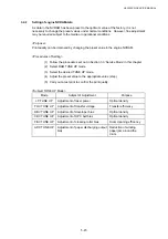
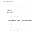
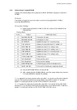
3.4.5
Initial setting of engine NVRAM
Implement the initial setting at the replacement of MCTL PWB after clearing the contents of
NVRAM.
<Purpose>
The number of images for each color will be reset when changing the MCTL PWB or
executing NVRAM INITIAL.
<Procedures of Setting>
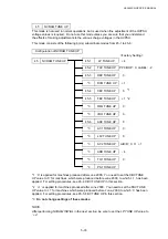
(1) Before replacing the MCTL PWB, confirm the contents of the NVRAM for the
following items.
“Factory Mode”
Code Subject
Confirmation
Value
43
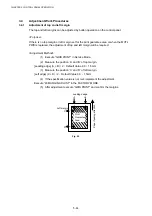
MARGIN ADJUST
Top margin set value
43
MARGIN ADJUST
Left margin set value
45
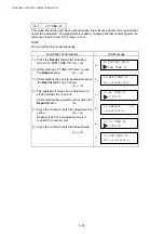
LP TUNE UP
Adjustment value (“+4” in ordinary case)
45
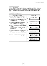
THV TUNE UP
Adjustment value (PPC/OHP “0”, LABEL “-2”)
45
DBV TUNE UP
Adjustment value (“0” in ordinary case)
45
CBV TUNE UP
Adjustment value (“0” in ordinary case) *1
45
FBV TUNE UP
Adjustment value (“+1” in ordinary case) *2
45
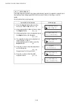
ADC TUNE UP
Adjustment value (“0” in ordinary case)
47
TOTAL PAGE SET
Total print count
47
LFU PAGE SET
Print count from LFU
47
DPL PAGE SET
Print count from Duplex
48
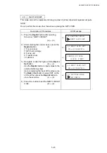
EACH IMAGE SET
Formed image count for 4 individual colors
49
NEXT LIFE SET
Print count for maintenance replacement parts
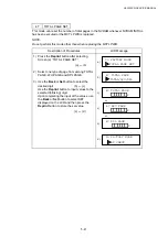
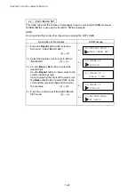
(2) Execute 46 NVRAM INITIAL in Factory Mode.
(3) After implementing the NVRAM INITIAL, input the values obtained in procedure
1) into the NVRAM to complete the settings.
*1 ’0’ is applied for machines produced after June 2000. You need to set the CBV TUNE UP
value to ‘0’ for machines which were produced before June 2000, to which ‘+1’ has been
applied. For setting procedures, see 45-4. CBV TUNE UP in this section.
*2 ‘+1’ is applied for machines produced after June 2000. You need to set the FBV TUNE
UP value to ‘+1’ for machines which were produced before June, 2000, to which ‘0’ has been
applied. For setting procedures, see 45-5. FBV TUNE UP in this section.
Summary of Contents for HL-3450CN Series
Page 15: ...HL 3450CN SERVICE MANUAL xiii 3 Rating Label For US For Europe 4 Operation Label 5 Jam Label ...
Page 17: ...HL 3450CN SERVICE MANUAL CHAPTER 1 PRODUCT OUTLINE ...
Page 27: ...HL 3450CN SERVICE MANUAL CHAPTER 2 SPECIFICATIONS ...
Page 39: ...CHAPTER 3 INSTALLATION ...
Page 54: ...HL 3450CN SERVICE MANUAL CHAPTER 4 STRUCTURE OF SYSTEM COMPONENTS ...
Page 104: ...HL 3450CN SERVICE MANUAL 4 51 Main PCB Circuit Diagram 1 8 CODE B512137CIR 1 8 LJ8907001 NAME ...
Page 106: ...HL 3450CN SERVICE MANUAL 4 53 Main PCB Circuit Diagram 3 8 CODE B512137CIR 3 8 LJ8907001 NAME ...
Page 108: ...HL 3450CN SERVICE MANUAL 4 55 Main PCB Circuit Diagram 5 8 CODE B512137CIR 5 8 LJ8907001 NAME ...
Page 110: ...HL 3450CN SERVICE MANUAL 4 57 Main PCB Circuit Diagram 7 8 CODE B512137CIR 7 8 LJ8907001 NAME ...
Page 126: ...HL 3450CN SERVICE MANUAL CHAPTER 5 CONTROL PANEL OPERATION ...
Page 173: ...HL 3450CN SERVICE MANUAL CHAPTER 6 PERIODIC MAINTENANCE ...
Page 208: ...CHAPTER 7 DISASSEMBLY RE ASSEMBLY ...
Page 264: ...HL 3450CN SERVICE MANUAL CHAPTER 8 TROUBLESHOOTING ...
Page 310: ...HL 3450CN SERVICE MANUAL 8 47 5 IMAGE FAILURE 1 2 3 4 5 6 7 8 9 a 9 b 10 11 12 13 14 ...
Page 311: ...CHAPTER 8 TROUBLESHOOTING 8 48 15 a 15 b 16 17 18 19 20 21 22 23 24 25 26 27 28 244m m 29 ...

