background image

USER’S GUIDE

3-12

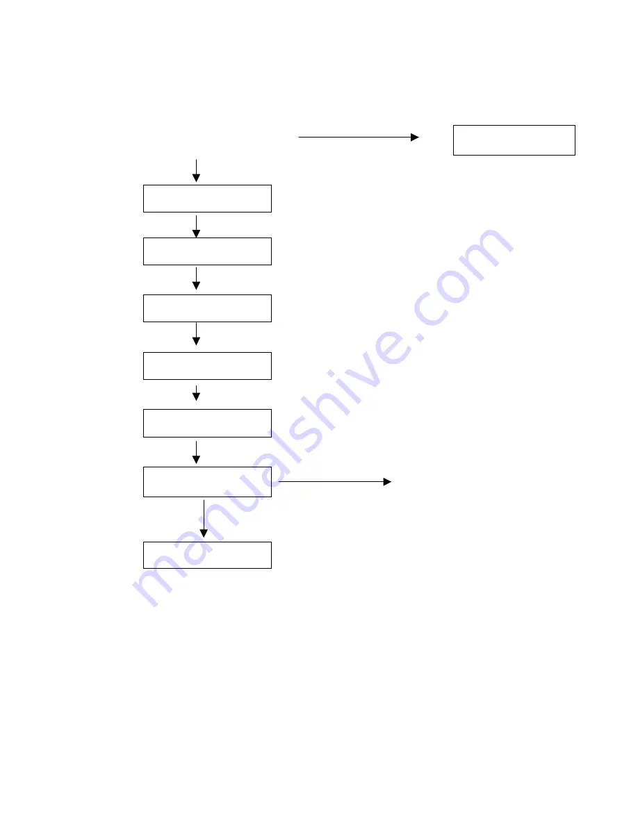
Operations for reprinting SECURE data

Press 

Reprint

switch.

There is no data.

NO DATA STORED

--REPRINT--
LAST JOB

Press the 

+

 or 

 switch.

--REPRINT--
SECURE

Press the 

Set

 switch.

SECURE
USER   

✶✶✶✶✶✶✶

Press the 

+

 or 

 switch to select the user name.

Press the 

Set

 switch to set the user name.

USER   

✶✶✶✶✶✶✶

JOB    

✶✶✶✶✶✶✶

Press the  

+

 or 

 switch to select the job.

Press the 

Set

 switch to set the job.

JOB    

✶✶✶✶✶✶✶

PASS NO.=  0000

Input your password.
Press the 

Set

 switch to set the password.

--REPRINT--
COPIES=       1

The printer will return from
this menu after a timeout.

Press the 

Set

 or 

Reprint

 switch.

If you press the 

Go

 switch, the display shows

PRESS SET TO PRINT

”.

PRINTING

Summary of Contents for HL-3260N

Page 1: ...I version C Brother Laser Printer HL 3260N USER S GUIDE Please read this manual thoroughly before using the printer Keep this manual in a convenient place for quick reference at all times ...

Page 2: ...gistered mark All other brand and product names mentioned in this user s guide are registered trademarks or trademarks of respective companies Compilation and Publication Under the supervision of Brother Industries Ltd this manual has been compiled and published covering the latest product descriptions and specifications The contents of this manual and the specifications of this product are subjec...

Page 3: ...r Service has installed an easy to use fax back system so you can get instant answers to common technical questions and product information for all Brother products This is available 24 hours a day 7 days a week You can use the system to send the information to any fax machine not just the one from which you are calling Call and follow the voice prompts to receive faxed instructions on how to use ...

Page 4: ...IV ...

Page 5: ...stomer Service has installed an easy to use fax back system so you can get instant answers to common technical questions and product information for all Brother products This is available 24 hours a day 7 days a week You can use the system to send the information to any fax machine not just the one from which you are calling Call and follow the voice prompts to receive faxed instructions on how to...

Page 6: ... es s The following conventions are used in this User s Guide Warning Indicates warnings that must be observed to prevent possible personal injury Caution Indicates cautions that must be observed to use the printer properly or prevent damage to the printer Note Indicates notes and useful tips to remember when using the printer ...

Page 7: ...aser radiation exposure do not remove any covers or screws other than those specified in this manual Turn off the power and disconnect the power plug by pulling the plug not the cord if any of the following conditions exist You spill something into the equipment You suspect that your equipment needs service or repair Your equipment s cover has been damaged Do not incinerate spilled toner or used t...

Page 8: ...w toner Keep toner used or unused and toner cartridges out of the reach of children For environmental reasons dispose of the equipment and supplies through an authorized dealer or an appropriate collection site Contact your local waste disposal facility for further specific instructions for your area Our products are engineered to meet the highest standards of quality and functionality When purcha...

Page 9: ... standard paper tray 1 20 Changing the paper size of the Paper tray 1 22 Printing on Labels Transparencies etc 1 29 C CH HA AP PT TE ER R 2 2 D DR RI IV VE ER R A AN ND D S SO OF FT TW WA AR RE E Printer driver 2 1 Features in the PCL printer driver only for Windows 2 2 Features in the PS printer driver only for Windows 2 9 Features in the bonus software only Windows users 2 14 Software for networ...

Page 10: ...R 3 3 C CO ON NT TR RO OL L P PA AN NE EL L Control panel 3 1 SWITCHES 3 2 GO switch 3 3 JOB CANCEL switch 3 4 SECURE PRINT switch 3 5 REPRINT switch 3 6 Switch 3 14 SET switch 3 15 BACK Switch 3 16 LEDs 3 17 LCD MESSAGES 3 18 Menus 3 22 ...

Page 11: ...t 4 14 Duplex unit DX 5000 4 20 Installing the Duplex Unit 4 20 Multi purpose tray MP 5000 4 29 Manual Feed 4 29 Installing the Multi purpose tray 4 29 Loading paper on the Multi purpose tray 4 35 Mailbox unit MX 5000 4 39 Installing the Mailbox 4 39 Bridge Unit BU 5000 4 44 Installing the Bridge Unit 4 44 Finisher Stapler FS 5050 4 50 Installing the Finisher Stapler 4 50 CompactFlash card 4 55 In...

Page 12: ...ii C CH HA AP PT TE ER R 5 5 M MA AI IN NT TE EN NA AN NC CE E S Su up pp pl li ie es s 5 1 T To on ne er r b bo ot tt tl le e 5 1 TONER LOW message 5 2 D Dr ru um m u un ni it t 5 7 Cleaning 5 13 Adding Staples 5 20 ...

Page 13: ...w to clear them 6 8 When Jam A appears 6 9 When Jam B appears 6 10 When Jam C appears 6 12 When Jam D appears 6 15 When Jam E appears 6 17 When Jam R appears 6 18 When Jam Y appears 6 19 When Jam Z appears 6 20 COVER OPEN message 6 22 Printer doesn t print 6 23 Improving print quality 6 24 Stains and Stripes 6 27 White Spots 6 28 Toner Scatter 6 28 Black Page 6 29 White Page 6 29 Dropout 6 30 Poor...

Page 14: ... purpose tray MP 5000 Appendix 8 Interchange unit Appendix 8 Duplex unit Appendix 9 Mailbox Appendix 9 Bridge unit Appendix 10 Finisher Stapler Appendix 10 RAM Appendix 10 PAPER SPECIFICATIONS Appendix 11 SYMBOL CHARACTER SETS Appendix 14 OCR Symbol Sets Appendix 16 HP LaserJet Mode Appendix 17 EPSON Mode Appendix 17 IBM Mode Appendix 18 HP GL Mode Appendix 18 Symbol Sets Supported by the Printer ...

Page 15: ...B digital device pursuant to Part 15 of the FCC Rules These limits are designed to provide reasonable protection against harmful interference in a residential installation This equipment generates uses and can radiate radio frequency energy and if not installed and used in accordance with the instructions may cause harmful interference to radio communications However there is no guarantee that int...

Page 16: ...iance Statement For Canada Only This Class B digital apparatus complies with Canadian ICES 003 Cet appareil numérique de la classe B est conforme à la norme NMB 003 du Canada International ENERGY STAR Compliance Statement The purpose of the International ENERGY STAR Program is to promote the development and popularization of energy efficient office equipments As an ENERGY STAR Partner Brother Indu...

Page 17: ...er operation FDA Regulations 110 120 V model only U S Food and Drug Administration FDA has implemented regulations for laser products manufactured on and after August 2 1976 Compliance is mandatory for products marketed in the United States The label shown on the back of the printer indicates compliance with the FDA regulations and must be attached to laser products marketed in the United States M...

Page 18: ... in conformity with the following normative documents Safety EN 60950 EN 60825 EMC EN 55022 Class B EN 55024 EN61000 3 2 EN61000 3 3 following the provisions of the Low Voltage Directive 73 23 EEC and the Electromagnetic Compatibility Directive 89 336 EEC as amended by 91 263 EEC and 92 31 EEC Issued by Brother Industries Ltd Information Document Company ...

Page 19: ...SE 1 LASER KLASSE 1 PRODUKT This printer has a Class 3B Laser Diode which emits invisible laser radiation in the Scanner Unit The Scanner Unit should not be opened under any circumstances Caution Use of controls adjustments or performance of procedures other than those specified in this manual may result in hazardous radiation exposure For Finland and Sweden LUOKAN 1 LASERLAITE KLASS 1 LASER APPAR...

Page 20: ...ily does not imply that the power is earthed and that the installation is completely safe For your safety if in any doubt about the effective grounding of the power consult a qualified electrician Operator Safety This machine is considered a CDRH class 1 laser device safe for office EDP use The machine contains 5 milliwat 700 800 nanometer wavelength GaAIAs laser diodes Direct or indirect reflecte...

Page 21: ...for your socket outlet remove the plug from the mains cord and fit an appropriate three pin plug If the replacement plug is intended to take a fuse then fit the same rating fuse as the original If a moulded plug is severed from the mains cord then it should be destroyed because a plug with cut wires is dangerous if engaged in a live socket outlet Do not leave it where a child might find it In the ...

Page 22: ... NEUTRAL BROWN LIVE The colors of the wires in the mains lead of this printer may not correspond with the colored markings identifying the terminals in your plug If you need to fit a different plug proceed as follows Remove a length of the cord outer sheath taking care not to damage the colored insulation of the wires inside ...

Page 23: ...es The wire which is colored green and yellow must be connected to the terminal in the plug which is marked with the letter E or by the safety earth symbol or colored green or green and yellow The wire which is colored blue must be connected to the terminal which is marked with the letter N or colored black or blue The wire which is colored brown must be connected to the terminal which is marked w...

Page 24: ...CHAPTER 1 ABOUT THIS PRINTER 1 1 C CH HA AP PT TE ER R 1 1 A AB BO OU UT T T TH HI IS S P PR RI IN NT TE ER R ...

Page 25: ...printer check to see that you have all of the following parts 1 Printer 2 Toner in the standard tray 3 Drum pre installed 4 CD ROM 5 AC power cord 6 Documents 7 Tray number seal These parts are in the Localization kit in Europe Fig 1 1 Note You may have additional parts that are not listed above depending on the country where you purchased the printer 1 3 2 4 5 6 7 ...

Page 26: ...y differ slightly from this figure depending on the country where you purchased the printer For parallel connections an IEEE 1284 bi directional parallel cable is recommended Most parallel cables support bi directional communication but some might have an incompatible pin assignment or may not be IEEE 1284 compliant Do not use a parallel cable that is longer than 3 meters 10 feet ...

Page 27: ...CHAPTER 1 ABOUT THIS PRINTER 1 3 What is on the CD ROM Fig 1 2 ...

Page 28: ...e 2 Manual User s guide Network Guide Technical Reviewer s Guide These guides are in PDF format 3 Brother Solutions Center Introduction to our user support web page You can easily access it and receive the latest drivers and information for this printer 4 Maintenance Tutorial See the maintenance videos for this printer We recommend that you view the videos before getting started 5 Make Disk sets C...

Page 29: ...apter 2 This printer supports with Mac OS 8 0 and 9 0 versions 3 Manual User s guide Network Guide Technical Reviewer s Guide These guides are in PDF format 4 Brother Solutions Center Introduction to our user support web page You can easily access it and receive the latest drivers and information for this printer 5 Readme 6 Screen Fonts When you use BR Script 3 PostScript level 3 language emulatio...

Page 30: ...vi ie ew w 6 5 4 7 8 9 1 2 3 Fig 1 4 1 Parallel interface port 2 Network interface port 3 CompactFlash slot for optional memory expansion 4 Output tray 5 Power switch 6 Upper right cover 7 Control panel 8 Front cover 9 Paper tray ...

Page 31: ...CHAPTER 1 ABOUT THIS PRINTER 1 7 3 4 2 1 Fig 1 5 1 Right cover 2 Lower right cover 3 Printer board cover 4 Power cord inlet ...

Page 32: ...1 8 1 6 2 5 4 3 Fig 1 6 1 Fusing unit 2 Transfer unit 3 Toner lock lever 4 Toner holder 5 Drum unit 6 Right cover ...

Page 33: ...nter base may be damaged P Po ow we er r s su up pp pl ly y Use the printer within the specified power range AC power 10 of the rated power voltage Frequency 50 60 Hz 220 240 V or 60 Hz 110 120 V Do not use an extension power cord Connect the printer power cord directly to the power socket Do not share the same power circuit with other high power appliances particularly an air conditioner copier s...

Page 34: ...al conditions Use the printer only within the following ranges of temperature and humidity 100 90 80 70 60 50 40 30 20 10 0 10 0 10 20 30 40 50 temperature humidity C 32 C 54 27 C 80 15 C 70 25 C 30 15 C 30 Possible operation range Recommended operation range ...

Page 35: ...tallation Leave enough space around the printer This space is necessary to operate the printer The recommended or minimum space requirements are as follows A B C D Fig 1 7 A more than 10cm 4 0 B more than 45cm 17 8 C more than 75cm 29 6 D more than 10cm 4 0 ...

Page 36: ... ...

Page 37: ...P 5000 4 Optional 500x2 sheets paper tray LT 5100 5 Optional 2000 sheets paper tray LT 5200 Fig 1 8 The printer loads paper from the installed standard paper trays optional Multi purpose tray or optional Lower paper trays Note This section refers to the standard paper tray For information about the optional Lower paper trays see Lower Tray Unit in Chapter 4 1 2 3 4 5 ...

Page 38: ...ptional multi purpose tray MP 5000 100 sheets cut sheet Custom Size 90 297 x 148 432mm 3 54 11 69 x 5 83 17 01 Plain paper Thick paper Transparencies 60 157 g m2 16 42 lb Optional 500x2 sheets paper tray LT 5100 500x2 sheets cut sheet A3 JIS B4 Ledger A4 ISO B5 A5 Legal Letter Executive Plain paper 60 105 g m2 16 28 lb Optional 2000 sheets paper tray LT 5200 2000 sheets cut sheet A4 or Letter Plai...

Page 39: ...sparencies 3M CG3300 3M CG3300 Envelopes Metric Crane Crest Before purchasing the large paper quantities please confirm by testing small quantities that no problems will occur with the printer Use paper made for plain paper copying Use paper which is 75 to 90 g m 2 Use neutralized paper avoid acidic or alkaline paper Use Long grain paper Use paper which has a Moisture content of around 5 ...

Page 40: ...r should be informed that the paper or envelopes will be used in a laser printer 2 Preprinted papers must use inks that can withstand the printer s fusing temperature 392 degrees Fahrenheit or 200 degrees centigrade 3 If selecting a cotton bond paper paper with a rough surface such as cockle or laid finished paper or paper that is wrinkled or puckered you may experience less than optimal performan...

Page 41: ...maged wrinkled or prefolded paper 5 Paper exceeding the recommended weight specified in this manual 6 Paper with tabs and staples 7 Letterheads using low temperature dyes or thermography 8 Multipart or carbonless paper DAMAGE OR OTHER DEFECTS CAUSED BY THE USE OF PAPER LISTED UNDER PAPER TYPES TO AVOID WILL NOT BE COVERED UNDER ANY WARRANTY OR SERVICE AGREEMENTS For more information about Special ...

Page 42: ... printing method that you require for your print job To print from the standard paper tray 1 or 2 See Loading Paper in the Standard paper tray in this chapter To print from the optional Multi purpose tray See Multi purpose tray in chapter 4 To print from the optional Lower tray See Lower Tray Unit in chapter 4 ...

Page 43: ...cies 60 157 g m2 16 42 lb Note If you load Thick paper or Envelopes set the printer to the Thick paper mode using the printer driver If you load Transparencies set the printer to the Transparencies mode using the printer driver If you set a paper size marked with a set the dial in the paper tray to and set the paper size on the Control Panel For more information about the Control Panel see Menus i...

Page 44: ... the paper size or feed direction see Changing the paper size of the Paper tray If you want to load paper in an Optional 500x2 Sheets Paper tray or Optional 2000 Sheets Paper tray see Loading Paper into the Lower tray unit in chapter 4 If you want to load paper in the Multi purpose tray see Loading paper in the Multi purpose tray in chapter 4 Follow these steps to set paper and install the paper t...

Page 45: ...g 1 10 Note Do not stack paper over the limit mark When you set custom size or thick paper in Paper tray 2 do not stack paper above the lower limit mark in Paper tray 2 ZAEY052E Fig 1 11 Set the paper after shuffling the sheets Load paper face up into the Paper tray 3 Slide the Paper tray into the printer until it stops ...

Page 46: ...nd feed direction of paper that can be set in the Paper tray see Print media and sizes in this chapter 1 Slide the Paper tray out until it stops ZAEY012E Fig 1 12 2 Set the Paper guide lock to the unlocked position ZAEY013E Fig 1 13 Caution Confirm that the lever of the paper guide lock is released before sliding the guides otherwise it can be damaged ...

Page 47: ...while pressing the release lever of the side guide 1 2 ZAEY021E Fig 1 14 4 Slide the rear guide fully to the left while pressing the release lever of the rear guide ZAEY034E Fig 1 15 5 Align all four sides of the paper stack and load it into the Paper tray ZAEY030E Fig 1 16 ...

Page 48: ...r limit mark in Paper tray 2 ZAEY052E Fig 1 17 Fan the paper before setting it in the Paper tray Load paper face up into the Paper tray 6 Align the side guide to the loaded paper size while pressing the release lever of the side guide 1 2 ZAEY031E Fig 1 18 7 Set the paper guide lock to the locked position ZAEY032E Fig 1 19 ...

Page 49: ...r size and feed direction of the paper in the Paper tray otherwise paper misfeeds or unexpected printing results might occur Confirm that the paper size dial matches the actual paper size loaded in the Paper tray If the actual paper size is not shown on the dial set the dial to and specify the paper size using the Control panel For more information on specifying the paper size see Paper handling i...

Page 50: ...1 26 Setting the Media from the Printer driver 1 Open the File menu and choose print 2 Open Properties and choose the Paper tab 3 Choose the paper size you want to use Fig 1 23 3 ...

Page 51: ...CHAPTER 1 ABOUT THIS PRINTER 1 27 4 Choose the Paper tray which you want to print from Fig 1 24 4 ...

Page 52: ...1 28 5 Choose the Media Type Fig 1 25 6 Click OK 5 ...

Page 53: ...g m2 16 42 lb Notes Be sure to select the same paper size as the paper to be used in your application software or correct printing cannot be obtained If your application software does not support paper size selection in its print menu you can change the paper size with the MP Size setting in the Paper menu on the Control panel switch For more information see Multi purpose tray in chapter 4 You can...

Page 54: ...ig 1 28 Note If the Thick paper mode is selected the following functions using Paper tray 2 are not available Duplex print Sort Shift sort Staple A yellow line appears under the paper size indicator on the front of the Paper tray Note Reset the lever to the left side after you have finished printing on thick paper Note For making settings from the printer driver see Settings the Media from the Pri...

Page 55: ...ith the only exposed spaces being lengthwise down the sheet Using labels with spaces may result in labels peeling off and causing serious jam or print problems All labels and transparencies used in this printer must be able to withstand a temperature of 200 degrees centigrade 392 degrees Fahrenheit for a period of 0 1 seconds Label and transparency sheets should not exceed the paper weight specifi...

Page 56: ... ...

Page 57: ...cause paper jams or misfeeds Do not print envelopes by Duplex printing Be sure to select the same paper size as the paper to be used from your application software or correct printing cannot be obtained If your application software does not support paper size selection on its print menu you can change the paper size with the MP Size setting in the Paper Menu on the Control Panel For more informati...

Page 58: ...ause of their construction A suitable envelope should have edges with a straight well creased folds and should not have more than two thickness of paper along the lead edge The envelope should lie flat and not have baggy or flimsy construction Purchase quality envelopes only from a supplier who understands that the envelopes will be used in a laser printer All envelopes should be tested prior to u...

Page 59: ...CHAPTER 2 BEFORE WORKING WITH THE PRINTER 2 2 C CH HA AP PT TE ER R 2 2 D DR RI IV VE ER R A AN ND D S SO OF FT TW WA AR RE E ...

Page 60: ...m are supplied on the CD ROM provided with the printer The latest printer driver can also be downloaded from Brother Solutions Center http solutions brother com For Windows 95 98 Me Windows NT 4 0 and Windows 2000 PCL Hewlett Packard laser printer LaserJet 5 driver BR Script PostScript Level3 language emulation driver For Macintosh BR Script PostScript Level3 language emulation driver For more inf...

Page 61: ...y y f fo or r W Wi in nd do ow ws s For more detailed information please see the on line help in the printer driver You can also change settings by clicking on the illustration on the left side of the tab Basic tab Fig 2 1 1 Select the Paper size Multi page Orientation etc 2 Select the Paper source etc 2 1 ...

Page 62: ... WORKING WITH THE PRINTER 2 3 Advanced tab Fig 2 2 Tab selection Change the tab setting by clicking on the icons as follows 1 Print Quality 2 Duplex 3 Watermark 4 Page Setting 5 Device options 6 Destination 2 1 3 4 5 6 ...

Page 63: ...duplex printing you need to install the optional Duplex unit and Interchange unit onto your printer If you select the duplex button the dialogue box for making duplex settings appears 6 types of duplex binding direction are available for each orientation Watermark You can put a watermarked logo or text into your documents When you use a bitmap file as a watermark you can change the size of the wat...

Page 64: ...INTER 2 5 Device options Fig 2 3 1 You can change the settings of the following printer functions in this tab Job Spooling Quick Print Setup Sleep Time Status Monitor Macro Administrator Insert Command File Page Protection Print Date Time ...

Page 65: ...er saves data that you identify as being required for reprinting Last job reprint Reprint the last job Secure Print Save the data with a password Public Save the data without a password Proof Save the data and print it Fig 2 4 For more information about reprint function see REPRINT switch in Chapter 3 ...

Page 66: ...utomatically and the available functions are reflected in the printer driver Recognize the Option automatically by pressing Auto options that are installed onto the printer will be listed You can manually add or delete options Tray settings etc will match the fitted options 2 Advanced Paper Source Setting Recognizes the paper size in each paper tray automatically 2 1 ...

Page 67: ...u can download the latest driver by accessing the Brother Solutions Center site You can see the printer driver version You can check the current driver settings You can print the Configuration page Test page etc Fig 2 6 ...

Page 68: ... at ti ib bl le e p pr ri in nt te er r d dr ri iv ve er r o on nl ly y f fo or r W Wi in nd do ow ws s For more information please see the on line help in the printer driver Details tab Select the port your printer is connected to or the path to the network printer you are using Select the printer driver which you installed Fig 2 7 ...

Page 69: ...e Multi page Orientation etc 2 Select the Paper source 3 When the Duplex unit or Mailbox unit is installed in the printer add the installed options in the Device Options Tab first The set the function for those devices by pressing this icon 2 1 3 ...

Page 70: ...CHAPTER 2 BEFORE WORKING WITH THE PRINTER 2 11 Graphics Set the print quality etc Fig 2 9 ...

Page 71: ... the setting and then select a new value in the Change Settings box Toner save Mode Sleep Mode Media Type HRC setting Collate only install the HDD or CompactFlash card Job spooling only install the HDD or CompactFlash card 2 Select the installed options from the lists 2 1 ...

Page 72: ...hout resending the data or sending the password from your PC because the printer saves data that you specify reprinting For more information see REPRINT Switch in Chapter 3 Secure Print Print the data with a password Public Save the data without a password Proof Save the data and print it ...

Page 73: ...tically You can also set it to select the mail to be printed automatically depending on the sender and the subject of the e mail Search E mail by the sender and subject and auto print As soon as an E mail is received the printer prints it without your having to start the print operation You can choose the mail you want to print by having the printer search by sender and subject Auto access at the ...

Page 74: ... PC with several people But Automatic E mail Printing supports multi users so several people can use their E mail software on one PC You can keep the current E mail software Even if you use Netscape or Microsoft Internet Mail you can use Automatic E mail Printing and get additional functions not supplied in the original e mail software ...

Page 75: ... you may have stored in the CompactFlash or 2 5 HDD You can print the fixed form document at any time by operating the Control panel To make the fixed document you must write Fonts Macros or fixed forms to the Storage Device in your printer Analysis Tool Software By adding an HDD to the HL 3260 printer you can gain a cost analysis capability Analysis Tool Software is a 32 bit Windows application d...

Page 76: ...izard to configure the printer TCP IP settings and specify the Printer driver to be used The Wizard can then create an Executable file which can be e mailed to other network users When run the Executable file installs the appropriate printer driver and network printing software directly on the remote PC To access the Network Printer Driver Wizard insert the CD ROM supplied with the printer click t...

Page 77: ...CD ROM by following these simple steps 1 Insert the CD ROM into the CD ROM drive The opening screen appears automatically If the screen does not appear click Start and choose Run enter the CD drive letter and type START EXE 2 Select the LANGUAGE and then follow the on screen instructions the printer driver will complete the installation ...

Page 78: ...er Driver may have been installed with your system software It is also available at http www apple com LaserWriter 8 version 8 6 and 8 7 have been tested for use with the Brother HL 3260 PostScript Printer Description Files PPDs PPDs in combination with the Apple LaserWriter 8 Driver access the printer features and allow the computer to communicate with the printer An installation program for the ...

Page 79: ...twork user 1 Turn on your Macintosh computer Insert the CD ROM into the CD ROM drive The following Window will appear automatically Fig 2 11 2 To install the BR Script PPD file click this icon 3 Set up the LaserWriter referring to the Network user s guide 2 ...

Page 80: ...he computer it automatically selects the emulation mode This function has been factory set to ON The printer can select the emulation among the following combinations EPSON default IBM HP LaserJet HP LaserJet BR Script 3 BR Script 3 HP GL HP GL EPSON FX 850 IBM Proprinter XL You can also select the emulation mode manually with the EMULATION menu in PRINT MENU mode by using the Control panel For mo...

Page 81: ...s the EPSON emulation mode you might need to select the IBM emulation mode with EMULATION menu in SETUP mode by using the Control panel when you need to use this emulation Try this function with your application software or network server If the function does not work properly select the required emulation mode manually using the printer panel switches or use emulation selection commands from your...

Page 82: ...rinter If a Network board Brother NC 4100h has been installed Select NETWORK mode by using the Control panel When necessary select the interface or the network communications parameters manually with the INTERFACE mode by using the Control panel For further information see Chapter 3 For the settings on the computer see the manual of the computer or software you are using Note When you use the Auto...

Page 83: ...u can operate the printer with these factory settings unchanged you can tailor the printer by making user settings Please see List of Factory settings in Chapter 3 Note Changing the user settings does not affect factory settings You cannot modify the preset factory settings The changed user settings can be restored to the factory default settings with the RESET MENU mode For further information se...

Page 84: ...CHAPTER 3 CONTROL PANEL 3 3 C CH HA AP PT TE ER R 3 3 C CO ON NT TR RO OL L P PA AN NE EL L ...

Page 85: ...CHAPTER 3 CONTROL PANEL 3 1 C Co on nt tr ro ol l p pa an ne el l Fig 3 1 ...

Page 86: ... ct t ti iio o on n n Go Exit from the Control panel menu Reprint settings and Clear error messages Pause Continue printing Job Cancel Stop and cancel the printer operation in progress Secure Print Print secure documents Reprint Select the Reprint menu Move forwards and backwards through Menus Move forwards and backwards through selectable options Set Select the Control panel menu Set the selected...

Page 87: ... it is possible to clear the error You can PAUSE printing with the Go switch during a print job Pressing the Go switch again makes the print job restart and clears the PAUSE During PAUSE the printer is in the off line state Note If you do not wish to print the remaining data when the printer is in PAUSE you can cancel the job by pressing the Job Cancel switch before pressing the Go switch to clear...

Page 88: ...USER S GUIDE 3 4 NO DATA JOB CANCELLING READY ...

Page 89: ...nter You can use the secure print function when the printer is READY or in the menu settings 1 Press the Secure Print switch 2 Select the user name the job password and the print copy quantity 3 Press the Set or the Secure Print switch to start printing Notes The secure print function does not support off line or paused printing When there is no secure data and you press the Secure Print switch th...

Page 90: ... do not install an HDD See HDD in Chapter 4 or Compact Flash Card see Compact Flash Card in Chapter 4 you can reprint from RAM When you use RAM to reprint 1 Press the Set switch on the Control panel to exit from the READY status and select RAMDISK SIZE in the SETUP mode 2 The default RAM is 0MB Press the switch to increase the reprint RAM size in 1MB steps Notes When you increase the RAM size to u...

Page 91: ...the panel and you press the Reprint switch the LCD shows NO DATA STORED for a short time If you want to cancel reprinting press the Job Cancel switch If the printer does not have enough memory to spool the print job data it prints the last page only Pressing the or switch makes the number or reprint copies decrease or increase You can select between COPIES 1 and COPIES 999 ...

Page 92: ...tion see Job Spooling in Chapter 2 2 Press the Reprint switch Press Reprint REPRINT COPIES 1 If you do not make a selection immediately the display clears the reprint menu automatically Press until the next screen as shown below is displayed REPRINT COPIES 3 Press Set or Reprint PRINTING Notes If you want to reprint the data and have pressed the Go switch the display shows PRESS SET TO PRINT Press...

Page 93: ... the area to spool data is full the earliest data is automatically deleted first The order of deleting data is not connected to the order of reprinting When you reprint PROOF data refer also to Operations for reprinting SECURE data in this chapter Notes If you have not installed the optional HDD or Compact Flash the reprint data is deleted when off the printer is turned off If there is data in the...

Page 94: ...hen you send it to the printer You must use the Control panel of the printer or connect to the printer through a web browser Public data can be deleted through the Control panel of the printer or from the web based management software When you reprint PUBLIC data refer also to Operations for reprinting SECURE data in this chapter Notes If there is data in the job information that cannot be display...

Page 95: ...e the control panel of the printer or connect to the printer using a web browser When you want to delete the spooled data you can carry out this operation on the control panel or in the web based management software Notes If there is data in the job information which cannot be displayed on the LCD the display shows You can also reprint the job by using the supplied printer driver For more informat...

Page 96: ...witch to select the user name Press the Set switch to set the user name USER JOB Press the or switch to select the job Press the Set switch to set the job JOB PASS NO 0000 Input your password Press the Set switch to set the password REPRINT COPIES 1 The printer will return from this menu after a timeout Press the Set or Reprint switch If you press the Go switch the display shows PRESS SET TO PRINT...

Page 97: ...ORED for a short time To delete the job Select the DELETE STORAGE menu under the SETUP menu of the Control panel Select the user name and the job to delete you need to input the password to delete secure data To cancel the reprint job Press the Job Cancel to cancel the current reprinting job The Job Cancel switch also allows you to cancel a reprint job which is paused by the Go switch ...

Page 98: ...ter other menus in the current mode by pressing the or switch Pressing the or switch scrolls the menus and settings forward or backward respectively on the display Press or keep pressing the switch until you access the desired item To set numbers When you want to set numbers there are two ways to input numbers either by scrolling up or down through the available setting range or by selecting the d...

Page 99: ... switch when the printer is the on line state it turns off line and the LCD goes to the menu display Pressing the Set switch allows you to set the selected menu or the default number After changing the menu or the number the asterisk mark appears on the right side for a short time ...

Page 100: ...digit when you input numbers by digits When the most left digit is selected the Back switch allows you to go up one level in the menu When a menu or number without an asterisk Set switch not pressed is selected the Back switch allows you to return to the previous menu level with the original setting unchanged Notes When you press the Set switch to select a setting an asterisk appears at the end of...

Page 101: ...D D D i iin n nd d di iic c ca a at t ti iio o on n n M M Me e ea a an n ni iin n ng g g On The printer power is on Off The printer power is off ALARM Red LED L L LE E ED D D i iin n nd d di iic c ca a at t ti iio o on n n M M Me e ea a an n ni iin n ng g g On An error has occurred in the printer DATA Green LED L L LE E ED D D i iin n nd d di iic c ca a at t ti iio o on n n M M Me e ea a an n ni i...

Page 102: ...D M ME ES SS SA AG GE ES S You can choose the messages to display on the second line on the LCD message as shown below Choose NONE PAGE COUNTER JOB NAME in the LOWER LCD menu of the SETUP mode READY READY PAGE xxx READY JOB NAME ...

Page 103: ...SE The printer has suspended printing or feeding paper Pressing the Go switch resumes printing paper feeding NOW INITIALIZING NOW INITIALIZING NOW INITIALIZING NOW INITIALIZING The printer is setting up WARMING UP WARMING UP WARMING UP WARMING UP The printer is warming up MEMORY MEMORY MEMORY MEMORY SIZE xx MB SIZE xx MB SIZE xx MB SIZE xx MB This printer has xx MB memory JOB CANCELLING JOB CANCEL...

Page 104: ...en you press the Set switch to select a setting an asterisk appears at the end of the display for a short time After that the display returns to the previous menu level Pressing the Back switch before you press the Set switch after changing the status or a number will return to the next previous menu level with the original settings unchanged When you input numbers you can do this by scrolling thr...

Page 105: ...he display MENU INFORMATION Press Press the or switch to scroll forward or backward through the Menu selections MENU PAPER Press Set Press the Set switch to enter the next level of the selected menu PAPER SOURCE Press PAPER MP FIRST Press Set MP FIRST OFF Press MP FIRST ON Press Set An asterisk appears at the end of the display for a short time MP FIRST ON The default setting is indicated by the ...

Page 106: ...SER S GUIDE 3 22 M Me en nu us s There are 8 modes If you want to see more information about each mode refer to the displays below INFORMATION PAPER QUALITY SETUP PRINT MENU NETWORK INTERFACE RESET MENU ...

Page 107: ...T FONTS PRINT FONTS PRINT FONTS PRINT FONTS Print the list of internal or resident fonts S S Su u ub b b S S Se e et t tt t ti iin n ng g g M M Me e en n nu u u D D De e es s sc c cr r ri iip p pt t ti iio o on n n VERSION VERSION VERSION VERSION SER NO SER NO SER NO SER NO Printer serial number ROM VER ROM VER ROM VER ROM VER ROM firmware version ROM DATA ROM DATA ROM DATA ROM DATA ROM date NET V...

Page 108: ...B5 A5 LETTER LEGAL EXECUTIVE TRAY4 TRAY4 TRAY4 TRAY4 SIZE SIZE SIZE SIZE A3 B4 LEDGER A4 B5 A5 LETTER LEGAL EXECUTIVE DUPLEX DUPLEX DUPLEX DUPLEX OFF ON LONG BIND ON SHORT BIND OUTPUT OUTPUT OUTPUT OUTPUT STANDARD FINISHER MAILBOX xx MX STACK MX SORT JOB OFFSET JOB OFFSET JOB OFFSET JOB OFFSET ON OFF Q Q Q Q Q Q Q Q Q Q Q QU U U U U U U U U U U UA A A A A A A A A A A AL L L L L L L L L L L LI I I ...

Page 109: ...TO EPSON AUTO IBM HP LASERJET KEEP PCL KEEP PCL KEEP PCL KEEP PCL OFF ON RAMDISK SIZE RAMDISK SIZE RAMDISK SIZE RAMDISK SIZE 0 1 2 MB RESTART DELETE STORAGE DELETE STORAGE DELETE STORAGE DELETE STORAGE Delete the data in compact Flash or HDD S S Su u ub b b S S Se e et t tt t ti iin n ng g g M M Me e en n nu u u SECURE FILE SECURE FILE SECURE FILE SECURE FILE USER NAME JOB NAME PASSWORD PUBLIC FIL...

Page 110: ...ARCH C5 and DL COPIES COPIES COPIES COPIES 1 999 You can set the number of copies to print Shows the number of copies still to print ORIENTATION ORIENTATION ORIENTATION ORIENTATION PORTRAIT or LANDSCAPE This printer can print pages in portrait or landscape orientation PRINT POSITION PRINT POSITION PRINT POSITION PRINT POSITION This printer can be adjusted to align the page format S S Su u ub b b S...

Page 111: ...OFF LF LF FF FF or VT VT AUTO WRAP AUTO WRAP AUTO WRAP AUTO WRAP OFF ON line feed and carriage return occur when the printer position reaches the right margin AUTO SKIP AUTO SKIP AUTO SKIP AUTO SKIP ON OFF line feed and carriage return occur when the printer position reaches the bottom margin LEFT MARGIN LEFT MARGIN LEFT MARGIN LEFT MARGIN Set the left margin at column 0 to 126 columns at 10 cpi R...

Page 112: ...PRINT Print code table OFF ON ON CR CR LF AUTO LF AUTO LF AUTO LF AUTO LF OFF CR CR AUTO MASK AUTO MASK AUTO MASK AUTO MASK OFF ON LEFT MARGIN LEFT MARGIN LEFT MARGIN LEFT MARGIN Set the left margin at column 0 to 126 columns at 10 cpi RIGHT MARGIN RIGHT MARGIN RIGHT MARGIN RIGHT MARGIN Set the right margin at column 10 to 136 columns at 10 cpi TOP MARGIN TOP MARGIN TOP MARGIN TOP MARGIN Set the t...

Page 113: ...HT MARGIN RIGHT MARGIN Set the right margin at column 10 to 136 columns at 10 cpi TOP MARGIN TOP MARGIN TOP MARGIN TOP MARGIN Set the top margin at a distance from the top edge of the paper 0 0 33 0 5 1 0 1 5 or 2 0 Factory setting 0 33 Non HP 0 5 HP BOTTOM MARGIN BOTTOM MARGIN BOTTOM MARGIN BOTTOM MARGIN Set the bottom margin at a distance from the bottom edge of the paper 0 0 33 0 5 1 0 1 5 or 2...

Page 114: ...I ON OFF DLC LLC DLC LLC DLC LLC DLC LLC ON OFF BANYAN BANYAN BANYAN BANYAN ON OFF LAT LAT LAT LAT ON OFF NETBIOS IP NETBIOS IP NETBIOS IP NETBIOS IP ON OFF ENET ENET ENET ENET AUTO 100B FD 100B HD 10B FD 10B HD I I I I I I I I I I I IN N N N N N N N N N N NT T T T T T T T T T T TE E E E E E E E E E E ER R R R R R R R R R R RF F F F F F F F F F F FA A A A A A A A A A A AC C C C C C C C C C C CE E ...

Page 115: ... ng g g M M Me e en n nu u u D D De e es s sc c cr r ri iip p pt t ti iio o on n n RESET PRINTER RESET PRINTER RESET PRINTER RESET PRINTER Resets the printer and restores all printer settings including command settings to settings you have previously made with the panel buttons FACTORY RESET FACTORY RESET FACTORY RESET FACTORY RESET Resets the printer and restores all printer settings including co...

Page 116: ... backward MENU SETUP Press Set Press the Set switch to enter the next lower mode SETUP LANGUAGE Press several times SETUP DATE TIME Press Set DATE TIME YEAR Press Set YEAR 1999 Press YEAR 2000 Press Set YEAR 2000 After a short time the display changes DATE TIME YEAR Press Set DATE TIME MONTH DATE TIME 2000 04 25 10 22 ...

Page 117: ... lower menu level of the selected menu NETWORK TCP IP Press Set TCP IP TCP IP ENABLE Press TCP IP IP ADDRESS Press Set IP ADDRESS 192 0 0 192 2 blinking The number that can be changed is blinking Press several times Press the or switch to increase or decrease the number IP ADDRESS 123 000 000 192 Press Set IP ADDRESS 123 000 000 192 Press IP ADDRESS 123 45 67 89 Press Set IP ADDRESS 123 45 67 89 ...

Page 118: ...r of this printer can control text and graphics on pages completely and satisfactorily If you want to obtain technical information about PostScript commands see the following commercial manuals Adobe Systems Incorporated PostScript Language Reference Manual 3rd Edition Menlo Park Addison Wesley Publishing Company Inc 1999 Adobe Systems Incorporated PostScript Language Program Design Menlo Park Add...

Page 119: ...erformance when printing from these types of applications EPSON FX 850 and IBM Proprinter XL Mode The EPSON FX 850 and IBM Proprinter XL modes are the emulation modes that this printer emulates to meet the industry standard for dot matrix printers of their respective manufacturers Some applications support these dot matrix printer emulations Use these emulation modes for optimum performance when p...

Page 120: ...i iin n ng g g PAPER PAPER PAPER PAPER SOURCE SOURCE SOURCE SOURCE AUTO MP FIRST MP FIRST MP FIRST MP FIRST OFF MP SIZE MP SIZE MP SIZE MP SIZE A4 LETTER MANUAL FEED MANUAL FEED MANUAL FEED MANUAL FEED OFF TRAY1 TRAY1 TRAY1 TRAY1 SIZE SIZE SIZE SIZE A4 LETTER TRAY2 TRAY2 TRAY2 TRAY2 SIZE SIZE SIZE SIZE A4 LETTER TRAY3 TRAY3 TRAY3 TRAY3 SIZE SIZE SIZE SIZE A4 LETTER TRAY4 TRAY4 TRAY4 TRAY4 SIZE SIZ...

Page 121: ...RINT POSITION PRINT POSITION PRINT POSITION X OFFSET 0 Y OFFSET 0 AUTO FF TIME AUTO FF TIME AUTO FF TIME AUTO FF TIME 5 FF SUPPRESS FF SUPPRESS FF SUPPRESS FF SUPPRESS OFF HP HP HP HP LASERJET LASERJET LASERJET LASERJET FONT NO FONT PITCH POINT SYMBOL CHARACTER SET TABLE PRINT AUTO LF OFF AUTO CR OFF AUTO WRAP OFF AUTO SKIP ON LEFT MARGIN RIGHT MARGIN TOP MARGIN BOTTOM MARGIN LINES EPSON FX 850 EP...

Page 122: ...N LINES HP GL HP GL HP GL HP GL CHAR SET STD CHAR SET ALT PEN SIZE DOTS PEN GRAY BR SCRIPT BR SCRIPT BR SCRIPT BR SCRIPT ERROR PRINT OFF APT OFF NETWORK NETWORK NETWORK NETWORK TCP IP TCP IP TCP IP TCP IP TCP IP ENABLE ON IP METHOD AUTO NETWARE NETWARE NETWARE NETWARE NETWARE ENABLE ON NET FRAME AUTO APPLETALK APPLETALK APPLETALK APPLETALK ON NETBEUI NETBEUI NETBEUI NETBEUI ON DLC LLC DLC LLC DLC ...

Page 123: ...CHAPTER 4 OPTIONS 4 4 C CH HA AP PT TE ER R 4 4 O OP PT TI IO ON NS S ...

Page 124: ...CHAPTER 4 OPTIONS 4 1 0 0 1 2 3 G F H C D E Fig 4 1 ...

Page 125: ...hot and can cause a burn injury if touched Before moving the machine unplug the power cord from the outlet Pulling the power cord can cause damage Damaged plugs or cords can cause an electrical or fire hazard When lifting the machine use the handholds on both sides of the printer to prevent damage to the machine or injury 1 5 2 3 4 6 7 1 2 Fig 4 2 Note Rating voltage of the connector for options m...

Page 126: ...installing the Interchange Unit See Installing the Duplex unit in this chapter 4 Installing Multi purpose tray MP 5000 Install the Multi purpose tray on the right hand side of the printer See Installing the Multi purpose tray in this chapter 5 Installing Mailbox MX 5000 Install the Mailbox on top of the Interchange Unit after installing the Interchange unit See Installing the Mailbox in this chapt...

Page 127: ...olds on both sides of the printer The machine could be damaged cause an injury if dropped It is dangerous to handle the plug with wet hands Doing this may result in receiving an electric shock Before moving the machine unplug the power cord from the outlet If the cord is unplugged abruptly it could become damaged Damaged plugs or cords can cause an electrical or fire hazard Place the printer on th...

Page 128: ...CHAPTER 4 OPTIONS 4 5 1 2 3 ZAEP380E Fig 4 3 1 Screws 4 pieces 2 Securing brackets 2 pieces 3 Installation Guide Note Tray number seal is only included with the printer ...

Page 129: ...ables and the power cord from the printer 3 Remove the adhesive tape and the packing materials Note Remove the adhesive tape fixing the cable to the paper feed unit after positioning the printer LT 5100 ZAEP480E Fig 4 4 LT 5200 ZAEP490E Fig 4 5 ...

Page 130: ...nd the paper feed unit then place the printer onto the paper feed unit Note When lifting the printer pull out the grips from the front of the printer Hold the grips at the front and hold the inset grips at the rear The printer should be lifted by at least two people ZAEP600E Fig 4 7 Do not trap the harness between the back of the paper feed unit and the printer ZAEP050E Fig 4 8 ...

Page 131: ...eir original position 7 Slide Paper tray 2 out until it stops Lift the front of the tray and then pull it out completely ZAEP060E Fig 4 9 8 Use a coin to fasten the two screws that secure the paper feed unit and the printer ZAEP070E Fig 4 10 9 Refit Paper tray 2 ...

Page 132: ... the paper feed unit and fasten the screws using a coin ZAEP080E Fig 4 11 11 Remove the adhesive tape holding the cable and connect the harness to the back of the printer ZAEP082E Fig 4 12 12 Push the cable of the connected harness into the groove provided until it stops ZAEP091E Fig 4 13 ...

Page 133: ...the hole after ensuring that the center push in peg is pulled out from the fastener as shown in the illustration 14 Attach cover 2 and secure cover 2 to the printer with the two screws ZAEP681E Fig 4 15 15 Turn the adjuster at the center bottom of the paper feed unit clockwise until it touches the floor ZAEP100E Fig 4 16 ...

Page 134: ...CHAPTER 4 OPTIONS 4 11 16 Fit the tray number seal directly below the paper size display on the front of the paper feed tray Fig 4 17 Note Use the tray number seal included with the printer ...

Page 135: ...4 12 0 1 2 0 1 2 3 4 5 6 0 6 7 6 2 ...

Page 136: ...paper tray in the same way as you do the upper paper tray See Loading paper in the standard paper tray in Chapter 1 S Se et tt ti in ng g t th he e M Me ed di ia a f fr ro om m t th he e P Pr ri in nt te er r D Dr ri iv ve er r See Setting the Media from the Printer Driver in Chapter 1 ...

Page 137: ...li in ng g t th he e I In nt te er rc ch ha an ng ge e u un ni it t 1 Confirm that the box also contains the following items Installation Guide 2 Turn off the printer and remove all cables and power cords from the printer 3 Remove the adhesive tape and the packing materials Fig 4 18 4 Open the right cover of the printer by lifting the catch ZAEP140E Fig 4 19 ...

Page 138: ...ZAEP630E Fig 4 20 6 Press the upper right cover in the direction as shown in the illustration and remove the upper right cover Note The upper right cover is no longer required but should be kept safely if you want to remove the Interchange unit in the future ZAEP150E Fig 4 21 ...

Page 139: ...safely if you want to remove the Interchange unit in the future ZAEP640E Fig 4 22 8 Put your fingers inside the upper cover of the printer and remove the cover by pulling it upwards Note The upper cover of the printer is no longer required but should be kept safely if you want to remove the Interchange unit in the future ZAEP650E Fig 4 23 ...

Page 140: ...e unit cover from the interchange unit Note The removed cover is required in Step 15 ZAEP500E Fig 4 24 10 Position the cable towards the back of the printer Place the interchange unit onto the printer as shown in the illustration ZAEP700E Fig 4 25 ...

Page 141: ...ght perpendicular to the printer Confirm that the projection locates in the hole as shown in the illustration 1 3 1 2 Fig 4 26 12 Fasten the two screws finger tight and secure the Interchange unit to the printer Use a coin to tighten the screws ZAEP161E Fig 4 27 13 Close the Upper right cover of the Interchange unit ZAEP162E Fig 4 28 ...

Page 142: ... Interchange unit cover that was removed in step 9 Attach the side of the cover facing the front of the printer first and then the other side of the cover Note To attach the mailbox go to Installing the Mailbox Step 6 ZAEP180E Fig 4 30 16 Attach the connector of the Interchange unit to the socket on the back of the printer as shown in the illustration ZAEP190E Fig 4 31 ...

Page 143: ...y to increase the installed RAM depending on the data you want to print If the printer cannot manage all the data for duplex printing at 600 dpi resolution it will automatically switch to simplex printing or decrease the resolution from 300 or 600 dpi to a lower resolution I In ns st ta al ll li in ng g t th he e D Du up pl le ex x U Un ni it t The installation procedure for the Duplex unit when t...

Page 144: ...OPTIONS 4 21 1 Confirm that the box also contains the following items 1 2 3 4 5 6 7 ZAEP382E Fig 4 32 1 Holder 2 Cover of the holder 3 Socket screws 3 pieces 4 Allen Key 5 Hook 6 Hook holder 7 Installation Guide ...

Page 145: ...and the power cord from the printer 3 Remove the adhesive tape and the packing materials Fig 4 33 4 Remove the two small covers from the top right hand side of the Interchange unit Note The removed small covers are no longer required ZAEP200E Fig 4 34 ...

Page 146: ...equired ZAEP511E Fig 4 35 6 Use the Allen Key to remove the two screws from the cover on the right hand side of the printer and remove the cover Note The removed screws and cover are no longer required ZAEP510E Fig 4 36 7 Fit the brackets of the holder into the slots on the side of the printer and push downwards slightly ZAEP210E Fig 4 37 ...

Page 147: ...ght top left bottom right and bottom left as viewed from the right hand side of the printer If the screws are not fastened in that order the duplex unit might not close completely or the Multi purpose tray might not work correctly ZAEP660E Fig 4 38 9 Remove the small cover on the right hand side of the printer Note The removed small cover is no longer required ZAEP230E Fig 4 39 ...

Page 148: ...he printer ZAEP231E Fig 4 40 11 Lower the duplex unit so that the groove in each arm of the unit locates onto the pin inside the holder as shown in the illustration ZAEP250E Fig 4 41 12 Locate the hole in the support bar of the duplex unit onto the pin on the hook that was attached in Step 10 and secure the bar by attaching the hook holder to the joint ZAEP260E 1 2 Fig 4 42 ...

Page 149: ...x unit will not close completely the holder was not installed correctly in Steps 7 and 8 Fasten the socket screws securely in the order described in Step 8 ZAEP270E Fig 4 43 14 Attach the connector of the duplex unit to the socket ZAEP280E Fig 4 44 ...

Page 150: ... Use the Allen key to fasten the two screws in the order as shown in the illustration to secure the cover to the holder ZAEP220E 1 2 Fig 4 45 Note When attaching the Multi purpose tray the cover of the holder is not required Keep the Allen Key in the housing inside the front cover ZAEP540E Fig 4 46 ...

Page 151: ...4 28 0 12 3 45 2 6 0 5 0 5 2 6 6 6 0 7RESOLUTION ADAPT8 5 ...

Page 152: ...or further information see Control Panel in Chapter 3 Note When you feed paper manually note the following If your application software supports a manual feed selection in the print menu you can select it through the software I In ns st ta al ll li in ng g t th he e M Mu ul lt ti i p pu ur rp po os se e t tr ra ay y The installation procedure for installing the Multi purpose tray when the Duplex u...

Page 153: ...hat the box also contains the following items 3 2 1 4 ZAEP430E Fig 4 47 1 Holder 2 Socket screws 2pieces 3 Allen key 4 Installation Guide 2 Turn off the printer and remove all cables and the power cord from the printer ...

Page 154: ...e and the packing materials ZAEP420E Fig 4 48 ZAEP530E Fig 4 49 Note If the Duplex unit is already installed the holder is no longer required Go to step 8 4 Use a coin to remove the two screws from the right hand side of the printer ZAEP201E Fig 4 50 ...

Page 155: ...ote The two removed screws and the cover are no longer required ZAEP510E Fig 4 51 6 Fit the brackets of the holder into the slots in the printer and push downward slightly ZAEP210E Fig 4 52 7 Use the Allen key to fasten the four screws in the order shown in the illustration to secure the holder to the printer ZAEP660E Fig 4 53 ...

Page 156: ...ork correctly 8 If the Duplex unit is not installed skip this step and go to step 9 If the Duplex unit is installed the plastic edges on each side of the unit must be removed The edges are held in place by four small posts Twist the edges to break the posts and remove them from the unit ZAEP290E Fig 4 54 9 Slide the Multi purpose tray into the printer by aligning the grooves of the right and left ...

Page 157: ...e illustration ZAEP310E Fig 4 56 11 Remove the adhesive tape holding the Multi purpose tray and cable and attach the connector to the socket on the bottom left hand side of the back of the printer ZAEP320E Fig 4 57 Note Keep the Allen key in the housing inside the front cover Only one Allen key can be kept in the housing ZAEP541E Fig 4 58 ...

Page 158: ...CHAPTER 4 OPTIONS 4 35 0 1 2 3 4 0 1 2 3 0 1 0 5 1 6 6 5 3 DX 5000 MX 5000 FS 5050 ...

Page 159: ...ides do not match the paper size image skew or a paper misfeed may occur Swing out the paper support extender when using paper sizes longer than A4 short edge feed 220 240V models or Letter 8 X11 short edge feed 110 120V models 2 Lift the paper guide lever ZAEY210E Fig 4 60 ...

Page 160: ...ing Do not stack paper over the limit mark otherwise image skew or paper misfeeds might occur When you set custom size or thick paper on the Multi purpose tray do not stack paper above the lower limit mark of the Multi purpose tray Shuffle the paper before setting it in the tray Check the print side of Transparencies Some Transparencies can only be printed on the specified side ...

Page 161: ...ig 4 62 Note If the paper guide lever is not pushed down paper misfeeds may occur 5 Turn on the printer 6 Configure the paper feed unit direction and the paper size Note The paper size specified with the printer driver overrides the one specified here ...

Page 162: ...have specified I In ns st ta al ll li in ng g t th he e M Ma ai il lb bo ox x Warning When lifting the machine use the hand holds on both sides of the printer If dropped the machine could be damaged or cause an injury Note To install the mailbox the Interchange unit must be installed first If you install the Mailbox and the Lower tray unit it is recommended that the Lower tray unit is installed fi...

Page 163: ...cables and the power cord from the printer 3 Remove the adhesive tape ZAEP440E Fig 4 64 4 If you installed the Duplex unit open the Duplex unit by lifting the catch ZAEP330E Fig 4 65 5 Open the right cover by lifting the catch ZAEP271E Fig 4 66 ...

Page 164: ...g the cover at the rear of the printer first as shown below ZAEP710E 1 2 Fig 4 67 Note If the cover of the Interchange unit is already removed go to Step 7 The removed cover is no longer required 7 Hold the Mailbox on both sides and fit it onto the top of the Interchange unit ZAEP340E Fig 4 68 ...

Page 165: ...ten the screws securely ZAEP350E Fig 4 69 9 Close the Right cover by pushing the area as shown in the illustration ZAEP690E Fig 4 70 10 If the Duplex unit is already attached close the unit 11 Slide the four mailbox output trays into the Mailbox unit starting from the bottom tray ZAEP360E Fig 4 71 ...

Page 166: ...CHAPTER 4 OPTIONS 4 43 0 0 1 0 2 ...

Page 167: ... installed later If the mailbox is already installed remove the four mailbox trays from the mailbox I In ns st ta al ll li in ng g t th he e B Br ri id dg ge e U Un ni it t 1 Confirm that the box also contains the following items Fig 4 72 1 Installation Guide 2 Bridge unit 3 Securing Plate 4 Knob Screw Caution Unplug the printer power cord before starting the following procedure 1 2 3 4 ...

Page 168: ...d cords from the printer 3 Remove the adhesive tape Caution Do not remove the adhesive tape holding the cable and the Bridge unit until the Bridge unit is attached in step 14 1 Fig 4 73 4 If you installed the Duplex unit open the Duplex unit by lifting the catch Fig 4 74 ...

Page 169: ...oin to remove the screw from the Front right cover and then remove the Front right cover Note The Front right cover has a clear film to prevent the removed screw falling in the printer Do not remove the screw from the film Fig 4 76 The removed screw and cover are required in step 11 ...

Page 170: ...s shown in the illustration Note The removed screw and cover are no longer required Fig 4 77 8 Return the Paper sensor into the Output tray as shown in the illustration Fig 4 78 9 Place the Bridge unit on the Output tray and slide the unit along the output part of the printer Fig 4 79 ...

Page 171: ...two Knob screws and secure the Bridge unit Fig 4 80 11 Replace the Front right cover removed in step 6 and then fasten the screw Fig 4 81 12 Close the Right cover by pushing the area as shown in the illustration Fig 4 82 ...

Page 172: ...ove the adhesive tape holding the Bridge unit and cable and packing material and attach the connector to the socket on the right top side of the back of the printer 15 Attach the securing plate as shown in the illustration Note The plate fastens with a screw when installing the Finisher Fig 4 84 ...

Page 173: ...ote If you install the Finisher the Bridge unit must be installed first Caution Before installing options the machine should be turned off and unplugged for at least thirty minutes Components inside the machine become very hot and can cause a burn injury if touched When lifting the machine use the grips on both sides The machine could break or cause an injury if dropped It is dangerous to handle t...

Page 174: ... Finisher tray 4 Finisher stand 5 Output guide 6 Screw 2pieces 7 Stopper 2pieces 2 Turn off the printer and remove all cables and the power cord from the printer 3 Remove the adhesive tape 1 Fig 4 86 Note Do not remove the adhesive tape holding the Finisher and cable until the Finisher is attached in step 10 1 2 3 3 4 5 6 ...

Page 175: ...g 4 87 5 Mount the brackets of the Finisher stand by placing them in the printer and then push it downwards slightly with catching it on the projection of the output guide 1 Fig 4 88 6 Use a coin to fasten the two screws that secure the Finisher stand to the Printer Fig 4 89 ...

Page 176: ...of the Finisher over the brackets of the Finisher stand and then push it downwards slightly Note If you do not keep the Finisher horizontal you can not install it correctly In this case remove the Finisher and reinstall it Fig 4 90 8 Insert the Finisher tray into the hole of the Finisher 1 Fig 4 91 ...

Page 177: ... stoppers to the lower of the Finisher output tray to lock the tray Fig 4 92 10 Remove the adhesive tape holding the Finisher and cable and packing material and attach the connector to the socket on the Bridge unit Fig 4 93 ...

Page 178: ... card For more information about the cards consult the dealer where you purchased the printer I In ns st ta al ll li in ng g a a C Co om mp pa ac ct tF Fl la as sh h C Ca ar rd d Follow these steps to install or remove a card 1 Make sure that the printer is turned off 2 Fit a compact flash card into the slot with the label facing you Make sure it is inserted correctly Fig 4 94 To remove the card p...

Page 179: ...o on n I In nc cl lu ud di in ng g 1 16 6 M Me eg ga ab by yt te es s o of f i in nt te er rn na al l m me em mo or ry y HP LaserJet HP GL EPSON FX 850 and IBM Proprinter XL emulation modes Page Protect Off 300 dpi 600 dpi Letter A4 standard standard Legal standard standard Ledger A3 standard standard Page Protect On 300 dpi simplex duplex 600 dpi simplex duplex Letter A4 standard standard standar...

Page 180: ...te TECHWORKS PM HP 64M BR 128 Megabyte TECHWORKS PM HP 128M BR In general the DIMM must have the following specifications Type 100 pin and 32 bit output CAS Lantency 2 or 3 Clock Frequency 66MHz or more Capacity 16 32 64 Megabyte or 128 Megabyte Height 46mm 1 8 inches or less Parity NONE DRAM Type SDRAM 4 Bank SDRAM can be used Note Some DIMMs might not work with this printer For more information ...

Page 181: ...urn off the printer and unplug the power cord from the AC outlet Note Be sure to turn off the power to the printer before installing or removing the DIMMs 2 Use a coin to remove the six screws and remove the Printer board cover Note The removed cover and screws are required in step 6 Fig 4 95 3 Unpack the DIMM and hold it by its edge Fig 4 96 ...

Page 182: ...edge Align the notches on the DIMM with the DIMM slot Check that the locks on each side of the DIMM slot are open or outward Fig 4 97 5 Press the DIMM straight into the slot press firmly Make sure the locks on each side of the DIMM snap inwards into place To remove a DIMM the locks must be released Fig 4 98 ...

Page 183: ...d disk at the same time it is not necessary to reattach the cover at this stage Fig 4 99 7 Reconnect the printer cable from your computer Plug the power cord into the AC outlet and turn on the printer 8 To check whether the DIMM has been installed correctly you may perform a Test Print Print Configuration that will print the current memory size ...

Page 184: ...rm that the box contains the following items Fig 4 100 1 HD 6G HD EX 2 Hard disk cables 2 Use the longer one 3 Shoulder screws 4 4 Screws 4 5 Setup guide 2 Turn off the printer and unplug the power cord from the AC outlet Disconnect the interface cable from the printer 3 Use a screwdriver to remove the six screws and remove the printer board cover Note The removed cover and screws are required in ...

Page 185: ...ig 4 102 5 Insert the 4 shoulder screws supplied with the HD 6G HD EX unit into the bottom of the HD 6G HD EX Fig 4 103 6 Fit the HDD base plate by fitting the 4 Screws into the 4 holes of the HDD base plate and secure the base plate to the shoulder screws with a screwdriver Fig 4 104 ...

Page 186: ...eyed side upwards ensuring it is correctly aligned Fig 4 105 8 Connect the flat cable to the main controller board Fig 4 106 9 Mount the HDD base plate and HD 6G HD EX assembly using the 3 screws that were removed in step 4 using a screwdriver to fasten the three screws Fig 4 107 ...

Page 187: ...n step 3 and use the screwdriver to fasten the six screws Fig 4 108 11 Reconnect the interface cable to the printer Plug the power cord into the AC outlet and then turn on the printer 12 Format the HD 6G HD EX from the Control panel See Chapter 3 for details ...

Page 188: ...CHAPTER 5 MAINTENANCE 5 5 C CH HA AP PT TE ER R 5 5 M MA AI IN NT TE EN NA AN NC CE E ...

Page 189: ...CHAPTER 5 MAINTENANCE 5 1 Fig 5 1 ...

Page 190: ... appears to stop or continue printing Note Do not incinerate spilled toner or used toner Toner dust is flammable and might ignite when exposed to an open flame If you dispose of the used toner containers yourself dispose of them according to local regulations Warning The inside of the machine becomes very hot Do not touch the parts which are labeled Hot Surface Touching a hot surface could result ...

Page 191: ...ctions Confirm the printer power is on Leave the Front cover open for more than 10 seconds Close the Front cover Follow these steps to change the toner bottle 1 Open the Front cover ZAET010E Fig 5 2 2 Lift the green handle ZAET020E Fig 5 3 3 While pushing the green lever downwards use the green handle to slide the Toner holder out slightly ZAET021E Fig 5 4 ...

Page 192: ...it stops Caution If you continue to push the green lever down while you continue to slide the Toner holder out the toner holder may fall out Fig 5 5 5 Push the Toner bottle backwards slightly until you can lift the top of the bottle upwards and gently pull out the bottle 1 2 ZAET040E Fig 5 6 ...

Page 193: ...r bottle by turning it counterclockwise ZAET030E 1 2 Fig 5 7 Note Do not remove the inside cap After removing the black cap from the bottle the toner can scatter easily Do not shake or jar the bottle 7 Push the Toner bottle into the toner holder and push the top of the bottle downwards to lock it in place ZAET040E 1 2 Fig 5 8 ...

Page 194: ...5 6 8 Slide the toner holder into the printer until it clicks into place and push down the green handle ZAET022E Fig 5 9 9 Close the Front cover ...

Page 195: ... changed CHANGE DRUM SOON Warning Do not incinerate the used drum unit Toner dust might ignite when exposed to an open flame Disposal should take place at an authorized dealer or an appropriate collection site If you dispose of the used parts yourself dispose of them according to local regulations 1 Turn off the printer ZAEH220E Fig 5 10 ...

Page 196: ...f the Duplex unit is installed open the Duplex unit by lifting the catch ZAEP330E Fig 5 11 3 Open the Right cover of the printer by lifting the catch ZAEP271E Fig 5 12 4 Open the Front cover ZAEM320E Fig 5 13 ...

Page 197: ...e Drum unit out ZAEM340E Fig 5 15 Note Do not tilt or drop the removed Drum unit Moving the unit abruptly can scatter toner While the Drum unit is removed do not change the toner 7 Take the new drum unit from the box and remove the plastic bag holding the Drum unit by the carrying handle Note Do not drop or refit the removed Drum Do not touch the side of the Drum ...

Page 198: ...n the order shown in the illustration ZAEM350E 1 2 Fig 5 16 Note Remove the drum unit keeping the unit parallel to the ground as shown in the illustration otherwise the toner in the unit might scatter Do not touch the inside of the unit or the green parts after the black protection sheet is removed 10 Align the new Drum unit onto the rail of the printer Slide the unit all the way into the printer ...

Page 199: ...om the Drum unit and remove the two pieces of tape ZAEM410E Fig 5 19 13 Close the right side cover of the printer ZAEM310E Fig 5 20 Note If the Right side cover of the printer cannot be closed it means that the Drum unit has not been properly installed Slide the Drum unit out and push it into the printer again until it clicks into place ...

Page 200: ...5 12 14 Close the Front cover ZAEM380E Fig 5 21 15 If the Duplex unit is installed close the Duplex unit cover ZAEP270E Fig 5 22 16 Turn on the printer ...

Page 201: ... off the printer power and allow it to cool down before cleaning Cleaning the Paper feed roller If the paper feed rollers are dirty with paper dust the paper may not feed correctly or paper jam In this case clean the paper feed rollers Follow these steps to clean the paper feed rollers in standard paper tray 1 and paper tray 2 1 Turn off the printer power 2 Slide Paper tray 1 and Paper tray 2 out ...

Page 202: ...g 5 24 4 Lift the green lever that is attached to the Paper feed rollers inside the printer on the lower right hand side and pull it towards you ZAEM090E Fig 5 25 5 Pull the Paper feed roller towards you then push it in a diagonally downward direction away from you and remove it ZAEM100E 1 2 Fig 5 26 ...

Page 203: ...Do not wipe with a wet cloth alcohol or cleanser 7 Insert the projection of the Paper feed roller into the hole While pulling the roller towards you insert the roller onto the rear shaft ZAEM110E 1 2 2 Fig 5 28 8 Check the motion of the Paper feed roller to confirm that it can rotate smoothly ZAEM101E Fig 5 29 ...

Page 204: ...on the paper size dial with both hands and slide it slowly into the second slot from the top until it stops ZAEM141E Fig 5 31 12 Hold Paper tray 1 with both hands and slide it slowly into the slot until it stops 13 If the optional Lower tray LT 5100 or LT 5200 is installed clean the Paper feed rollers of Paper tray 3 or Paper tray 4 following the steps for Paper tray 1 and Paper tray 2 ...

Page 205: ...dard Paper tray 2 1 Turn off the printer power 2 Slide Paper tray 2 out until it stops ZAEY012E Fig 5 32 3 Wipe the top of the Friction pad with a dry cloth ZAEY017E Fig 5 33 Note Do not wipe with a wet cloth alcohol or cleanser 4 Slide Paper tray 2 into the slot slowly until it stops 5 If 2000 Sheets paper tray LT 5200 is installed clean the Friction pads of Paper tray 3 or Paper tray 4 following...

Page 206: ...lean the Pad inside the paper tray Follow these steps to clean the Pad inside standard Paper tray 2 1 Turn off the printer power 2 Slide Paper tray 2 out until it stops ZAEY012E Fig 5 34 3 If there is paper in the Paper tray remove the paper 4 Wipe the pad inside the Paper tray with a dry cloth ZAEY035E Fig 5 35 Note Do not wipe with a wet cloth alcohol or cleanser ...

Page 207: ...ad paper and slide Paper tray 2 into the printer slowly until it stops 6 If the 2000 Sheets paper tray LT 5200 is installed clean the Friction pads of Paper tray 3 or Paper tray 4 following the steps for Paper tray 1 and Paper tray 2 ...

Page 208: ... appears on the Control panel the staples have run out Follows these steps to add a new staple refill Note After adding the Staple refill Staples might not be ejected for the first few times 1 Open the Rear cover of the Finisher Fig 5 36 2 Remove the empty cartridge Fig 5 37 ...

Page 209: ...e as shown in the illustration ZAEH190E Fig 5 38 4 Align the arrows on the new refill case and the cartridge and push the new refill case in until it clicks ZAEH191E Fig 5 39 Note Do not remove the ribbon securing the staples before installing the cartridge ...

Page 210: ...5 22 ZAEH200E Fig 5 40 Fig 5 41 ...

Page 211: ...CHAPTER 6 TROUBLESHOOTING 6 6 C CH HA AP PT TE ER R 6 6 T TR RO OU UB BL LE E S SH HO OO OT TI IN NG G ...

Page 212: ...lbox cover is open Close the Mailbox cover COVER OPEN Close the Bridge Unit Cover The Bridge unit cover is open Close the Bridge unit cover COVER OPEN Close the Finisher Cover The Finisher cover is open Close the Finisher cover COVER OPEN Close the Right Cover The Right cover is open Close the Right cover COVER OPEN Close the Paper Tray Right Cover The Paper tray right cover is open Close the Pape...

Page 213: ...ze specified Paper size in the Finisher is wrong Load the right size of paper SIZE ERROR ST The Stapler does not accept the size specified Paper size in the Stapler is wrong Load the right size of paper SIZE ERROR MX The Mailbox unit does not accept the size specified Specify the correct paper size A4 or Letter Paper size in the Mailbox unit is wrong Load the right size of paper for use in the Mai...

Page 214: ... card was removed while the printer was turned on Turn off the printer and then turn it back on again BUFFER ERROR Check the cable connection between the computer and printer Interface communication error Check the interface setting DOWNLOAD FULL The download buffer of the printer is full Add more memory to the printer Download font overflow Add memory FONT FULL The font memory area is full Delete...

Page 215: ...tting MEDIATYPE ERROR Specify the correct media type xx Load correct media type of paper DIMM ERROR Ensure that the DIMM is installed correctly Installed DIMM is poor or incorrectly connected Turn off the printer and check the DIMM STORAGE FULL There is no more space on the device delete some files or format the drive The HDD or the Compact flash is full Delete unwanted storage data M Ma ai in nt ...

Page 216: ...inter Off wait 5 seconds and then turn the printer On again If this does not clear the problem consult your dealer or our authorized service representative S S Se e er r rv v vi iic c ce e e C C Ca a al lll ll M M Me e es s ss s sa a ag g ge e e A A Ac c ct t ti iio o on n n ERROR SERVICE CALL Turn off the printer Wait a few seconds then turn it on again ...

Page 217: ... properly they might be jammed Note Staples might jam because of curled paper In this case try turning the paper over in the tray After removing the jammed staples staples might not be ejected for the first few times 1 Open the Front cover of the finisher Fig 6 1 2 Remove the cartridge Fig 6 2 ...

Page 218: ...n the Face plate of the cartridge ZAEH210E Fig 6 3 4 Remove the jammed Staples ZAEH210E Fig 6 4 5 Close the Face plate of the cartridge 6 Reinstall the cartridge It should click into place Fig 6 5 7 Close the Front cover of the Finisher ...

Page 219: ...uch the fusing section because it becomes very hot Note More than one jammed area might be indicated In this case check every applicable area See the following illustrations Fig 6 6 If paper continues to jam check the following points Confirm that the setting of the paper size dial matches the size and feeding direction of the paper loaded in the paper tray Confirm that the toner bottle is install...

Page 220: ...am m A A a ap pp pe ea ar rs s 1 Open the Lower right cover 1 ZAEH040E Fig 6 7 2 Remove the jammed paper from inside the Lower right cover 1 ZAEH041E Fig 6 8 3 Close the Lower right cover 1 Note Close the cover by pushing the center area of the cover ...

Page 221: ... Ja am m B B a ap pp pe ea ar rs s 1 Open the Duplex unit by lifting the catch ZAEP331E Fig 6 9 2 Open the Right cover by lifting the catch Fig 6 10 3 Remove the jammed paper from inside the Right cover ZAEY190E Fig 6 11 ...

Page 222: ...TROUBLESHOOTING 6 11 4 Close the Right cover before closing the Duplex unit 5 If the jammed paper is inside the Multi purpose tray while lifting the Paper guide lever remove the jammed paper ZAEY191E 1 2 Fig 6 12 ...

Page 223: ... am m C C a ap pp pe ea ar rs s When the Interchange unit is not installed 1 Open the Right cover by lifting the catch ZAEP140E Fig 6 13 2 Open the Upper right cover by pulling the handle and remove the jammed paper Fig 6 14 ...

Page 224: ...CHAPTER 6 TROUBLESHOOTING 6 13 3 Close the Upper right cover before closing the Right cover Fig 6 15 ...

Page 225: ...331E Fig 6 16 2 Open the Right cover by lifting the catch and open the Upper cover of the interchange unit by pulling the handle ZAEH051E 1 2 Fig 6 17 3 Remove the jammed paper ZAEH060E Fig 6 18 4 Close the covers in the following order the Upper right cover the Right cover and the Duplex unit ...

Page 226: ...ap pp pe ea ar rs s 1 Open the duplex unit by lifting the catch ZAEP331E Fig 6 19 2 Open the Right cover by lifting the catch and open the Upper cover of the Interchange unit by pulling the handle ZAEH051E 1 2 Fig 6 20 3 Remove the jammed paper ZAEH060E Fig 6 21 ...

Page 227: ...3 open the Upper cover of the Bridge unit and remove the jammed paper Fig 6 22 5 If the jammed paper is not removed in step 4 open the Right cover of the Bridge unit and remove the jammed paper ZAEY080E 1 2 Fig 6 23 6 Close the cover of the Bridge unit ...

Page 228: ...APTER 6 TROUBLESHOOTING 6 17 W Wh he en n J Ja am m E E a ap pp pe ea ar rs s 1 Open the cover of the Mailbox ZAEH090E Fig 6 24 2 Remove the jammed paper ZAEY100E Fig 6 25 3 Close the cover of the Mailbox ...

Page 229: ...a ar rs s 1 Remove the jammed paper inside the Finisher tray Fig 6 26 2 If the jammed paper is not removed in step 1 open the Top cover of the Finisher Fig 6 27 3 Remove the jammed paper inside the cover Fig 6 28 4 Close the cover of the Finisher ...

Page 230: ...TROUBLESHOOTING 6 19 W Wh he en n J Ja am m Y Y a ap pp pe ea ar rs s 1 Open the Lower right cover 2 ZAEH140E Fig 6 29 2 Remove the jammed paper inside the cover ZAEY150E Fig 6 30 3 Close the Lower right cover 2 ...

Page 231: ...unit by lifting the catch ZAEP331E Fig 6 31 2 While lifting the lever lift cover Z1 and remove the jammed paper Z1 ZAEY160E 1 2 Fig 6 32 3 If the jammed paper is not removed in step 2 while lifting the lever lift cover Z2 and remove the jammed paper Z2 ZAEY170E 1 2 Fig 6 33 ...

Page 232: ...CHAPTER 6 TROUBLESHOOTING 6 21 4 Close cover Z2 and then cover Z1 Z 1 Z 2 Fig 6 34 5 Close the Duplex unit ...

Page 233: ...6 22 C CO OV VE ER R O OP PE EN N m me es ss sa ag ge e Fig 6 35 ...

Page 234: ...print a configuration page it probably indicates a printer malfunction You should contact your sales or service representative If you can print a configuration page but cannot get the printer to print when you issue a print command from your computer it probably means there is a problem with your computer Also keep it in mind that large complex data might take a long time for the printer to proces...

Page 235: ...the paper is hazy gray If paper is curled replace the paper The back of the printed output is hazy gray Check if the size setting on the paper tray dial matches the setting on Control panel If not set it to the size and feed direction of the paper loaded in the tray If you print something after printing on paper whose size is smaller than the actual document size the back of the next output may be...

Page 236: ...The paper is upside down in the tray turn it over Check the paper size settings The size specified with the paper size dial might be different from the actual paper size Make the correct dial setting See Changing the paper size of the paper tray in Chapter 1 Use the recommended paper Avoid using curled folded or wrinkled paper perforated paper or glossy paper See Recommended Paper in Chapter 1 Con...

Page 237: ... display Before printing use the print preview to see how the page will look when printed If necessary adjust the settings It takes a long time to resume printing The data is so large or complex that it takes time to process it If the Data lamp is blinking the data processing is being done Just wait until it resumes Image is printed in the wrong orientation Specify the correct orientation in the p...

Page 238: ...One thing I can tell you is you go to be free Come tin the sky right now over me Here come A Pat top he come One thing I can tell you is you go to be free Come in the sky right now over me HereA come Pat top he come One thing I can tell you is you go to be free Come tin the sky right now over me A Here come Pat top he come One thing I can tell you is you go to be free Come together right now over ...

Page 239: ... ca at tt te er r If toner scatters around printed characters and stains the printed page clean the printer interior See Cleaning in Chapter 5 Fig 6 38 If the same print problem occurs after cleaning take any of the following actions Make sure that you use paper Transparencies or envelopes that meet the printer s specifications Check for glue on the paper Glue causes toner to scatter If toner scat...

Page 240: ...ve paper or it may cause this problem Fig 6 39 W Wh hi it te e P Pa ag ge e If nothing is printed on pages make sure that the toner bottle is not empty and that you are using paper Transparencies or envelopes that meet the printer s specifications If a stack of paper is not fanned more than one sheet may be loaded at a time which may cause blank pages to be ejected Fig 6 40 ...

Page 241: ...y with AAAAA Diamonde One thing I can tell you is you go to be free Come tin the sky right now over me Here come A Pat top he come One thing I can tell you is you go to be free Come in the sky right now over me HereA come Pat top he come One thing I can tell you is you go to be free Come tin the sky right now over me A Here come Pat top he come One thing I can tell you is you go to be free Come to...

Page 242: ...APPENDICES A AP PP PE EN ND DI IC CE ES S ...

Page 243: ...OS 8 0 and 9 0 600 300dpi HRC High Resolution Control For 300 600dpi The resolution can be enhanced by using the high resolution control feature Print Speed 32 pages per minute 600 or 300 dpi A4 Letter size simplex 25 pages per minute 600 or 300 dpi A4 Letter size duplex Warm Up Less than 45 seconds at 20 C 68 F First Print Less than 5 seconds Letter A4 size by face down print delivery from Paper ...

Page 244: ...r model and country where it is purchased Interface Automatic interface selection between IEEE 1284 Parallel 10 100 TX Ethernet Network Connectivity Interface 10 100 Base TX Ethernet Protocols TCP IP AppleTalk IPX SPX DEC LAT Banyan VINES NetBEUI DLC LLC Management BRAdimin32 Brother original Windows utility for print server management Web Based Management Printer and printer server management thr...

Page 245: ...Emulation Automatic emulation selection PCL6 BR Script Level 3 HP GL EPSON FX 850 IBM Proprinter XL Resident Printer HP LaserJet EPSON FX 850 and IBM Proprinter XL Fonts modes 66 scalable fonts 12 bitmapped fonts and 11 bar codes BR Script Level 3 mode 165 scalable fonts ...

Page 246: ... Windows NT 4 0 Windows 2000 and Apple Mac OS 8 0 and 9 0 Ethertalk only Utility Software Automatic E mail Printing Utility software that automatically prints specified E mail message at a prescheduled time Windows 95 98 Me Storage Manager HDD or CompactFlash can be controlled Windows 95 98 Me Analysis Tool Software The printer log can be investigated Network Print Software Network Printer Driver ...

Page 247: ...ompatible for CompactFlash Type I and II Diagnostics Self diagnostic program O OT TH HE ER RS S Power Consumption Printing full options Less than 1 000 WH Stand by Less than 145 WH Sleep Less than 40 WH Noise Level Printing Mainframe only Less than 53 dB Stand by Less than 30 dB Ecology Power Saving Yes Toner Saving Yes Temperature Operating 10 C to 32 C 50 F to 90 F Storage 0 to 35 C 38 F to 95 F...

Page 248: ...options 950 W x 538 H x 1140 D mm 37 4 x 21 8 x 44 9 inches Weight Approx 40 kg 88 18 lbs Without options S SU UP PP PL LI IE ES S Toner Toner is a single component toner bottle Life Expectancy 12 000 single sided pages bottle A4 or letter size paper with the print density set at level 7 with about 5 coverage Drum 60 000 A4 LTR pages 1 page job and long edge feeding Staples Min 3000 staples cartri...

Page 249: ...ter 1 Power Consumption 17W or less Average Dimensions 550 W x 520 D x 271 H mm 21 7 x 20 5 x 10 7 inches Weight 25kg 55 6lb 2 20 00 00 0 s sh he ee et ts s p pa ap pe er r t tr ra ay y L LT T 5 52 20 00 0 Paper Size Weight Capacity See Print Media and Sizes in Chapter 1 Power Consumption 14W or less Average Dimensions 550 W x 520 D x 271 H mm 21 7 x 20 5 x 10 7 inches Weight 25kg 55 6lb ...

Page 250: ...e Multi purpose tray in Chapter 4 Power Consumption 10W or less Average Dimensions 125 W x 495 D x 163 H mm 4 9 x 19 5 x 6 4 inches Weight 2 5kg 5 6lb I In nt te er rc ch ha an ng ge e u un ni it t Power Consumption 10W or less Average Dimensions 135 W x 515 D x 123 H mm 5 3 x 20 3 x 4 8 inches Weight 1kg 2 2lb ...

Page 251: ...er Consumption 10W or less Average Dimensions 90 W x 495 D x 452 H mm 3 5 x 19 5 x 17 8 inches Weight 7kg 15 6lb M Ma ai il lb bo ox x Paper Size Weight Capacity See Mailbox in Chapter 4 Power Consumption 17W or less Average Dimensions 440 W x 520 D x 370 H mm 17 3 x 20 5 x 14 6 inches Weight 7 kg 15 6lb ...

Page 252: ...6 H mm 17 4 x 19 6 x 6 1 inches Weight 5 kg 11 1lb Other Full stack detection is available F Fi in ni is sh he er r S St ta ap pl le er r Paper Size Weight Capacity See PAPER SPECIFICATION in Appendix Power Consumption 48 W Dimensions 149 W x 490 D x 230 H mm 5 9 x 19 3 x 9 1 inches Weight 10 kg 22 2 lb H HD DD D See HDD in Chapter 4 R RA AM M See RAM Expansion in Chapter 4 ...

Page 253: ...APPENDICES Appendix 11 0 1 0 2 3 4 42 5 5 4 5 25 0 1 0 2 ...

Page 254: ...ive Envelopes Com10 C5 DL Monarch Proof tray 60 157 g m2 16 42 lb Bridge to the finisher 60 105 g m2 16 28 lb Finisher 500 sheets A4 Legal Letter Executive 250 sheets A3 JIS B4 Ledger Stapler One staple for 20 sheets A3 JIS B4 Ledger Legal One staple for 30 sheets A4 Letter Mailbox 125 sheets per bin A3 JIS B4 Ledger A4 ISO B5 A5 Legal Letter Executive 60 105 g m2 16 28 lb Duplex unit A3 JIS B4 Le...

Page 255: ...k Printing Yes Other Quick Print Setup 1 Yes Secure Printing Yes 2 1 A printer driver function that enables you to change the driver settings without opening the Property dialog box 2 When the optional HD 6G HD EX is installed Proof Public Private Print Only D DI IM ME EN NS SI IO ON NS S W WE EI IG GH HT T Dimensions 550 x 538 x 516mm 21 65 x 21 81 x 20 31 inches printer Weight 40kg 88 18 lbs ...

Page 256: ... Letter Gothic 16 66 cpi ISO 8859 1 Latin6 PcTENNESSEE Scalable PC Tennessee OKLAHOMA Scalable Oklahoma CONNECTICUT Scalable Connecticut CLEVELAND Cd Scalable Cleveland Condensed PcBRUSSELS Scalable PC Brussels UTAH Scalable Utah UTAH CONDENSED Scalable Utah Condensed AntiqueOAKLAND Scalable Antique Oakland GUATEMALA Scalable Guatemala Antique MARYLAND Scalable Maryland ALASKA Scalable Alaska HELS...

Page 257: ...ISH PC 865 PC 852 SWEDISH PC 8 TURKISH PC 8 TURKISH JAPANESE PC 1004 WINDOWS LATIN1 NORWEGIAN WINDOWS LATIN2 DANISH II WINDOWS LATIN5 UK ASCII II WINDOWS BALTIC LEGAL FRENCH II ISO 2 IRV DUTCH ISO 4 UK SOUTH AFRICAN ISO 6 ASCII PC 8 ISO10 SWE FIN PC 8 D N ISO11 SWEDISH PC 850 ISO14 JISASCII PC 852 ISO15 ITALIAN PC 860 ISO16 POR PC 863 ISO17 SPANISH PC 865 ISO21 GERMAN PC 8 TURKISH ISO25 FRENCH ISO...

Page 258: ...et EPSON FX 850 and IBM Proprinter XL emulation modes See Control Panel in Chapter 3 When you have selected the HP GL emulation mode you can select the standard or alternate character set from the control panel See Control Panel in Chapter 3 O OC CR R S Sy ym mb bo ol l S Se et ts s When the OCR A or OCR B font is selected the corresponding symbol set is always used ...

Page 259: ...ode values with which characters are to be replaced in the Roman 8 character set For other characters see the Roman 8 character set E EP PS SO ON N M Mo od de e The following table shows characters available only in the corresponding character set The numbers at the top of the table are hexadecimal code values with which characters are to be replaced in the US ASCII character set For other charact...

Page 260: ...Appendix 18 I IB BM M M Mo od de e H HP P G GL L M Mo od de e ...

Page 261: ...tin5 7J DeskTop 9J PC 1004 OS 2 10J PS Text 13J Ventura International 14J Ventura US 6J Microsoft Publishing 8M Math 8 5M PS Math 6M Ventura Math 15U PI Font 1U Legal 1E ISO 4 United Kingdom 0U ISO 6 ASCII 2U ISO 2 IRV 0S ISO 11 Swedish names 0I ISO 15 Italian 1S HP Spanish 2S ISO 17 Spanish 3S ISO 10 Swedish 4S ISO 16 Portuguese 5S ISO 84 Portuguese 6S ISO 85 Spanish 0G HP German 1G ISO 21 German...

Page 262: ...tional 14J Ventura US 6J Microsoft Publishing 8M Math 8 5M PS Math 6M Ventura Math 15U PI Font 1U Legal 1E ISO 4 United Kingdom 0U ISO 6 ASCII 2U ISO 2 IRV 0S ISO 11 Swedish names 0I ISO 15 Italian 1S HP Spanish 2S ISO 17 Spanish 3S ISO 10 Swedish 4S ISO 16 Portuguese 5S ISO 84 Portuguese 6S ISO 85 Spanish 0G HP German 1G ISO 21 German 0D ISO 60 Norwegian 1 1D ISO 61 Norwegian 2 0F ISO 25 French 1...

Page 263: ...26U PC 775 9T PC Turk 19U Windows 3 1 Latin1 9E Windows 3 1 Latin2 5T Windows 3 1 Latin5 7J DeskTop 9J PC 1004 OS 2 10J PS Text 13J Ventura International 14J Ventura US 6J Microsoft Publishing 8M Math 8 5M PS Math 6M Ventura Math 15U PI Font 1U Legal 1E ISO 4 United Kingdom 0U ISO 6 ASCII 2U ISO 2 IRV 0S ISO 11 Swedish names 0I ISO 15 Italian 1S HP Spanish 2S ISO 17 Spanish 3S ISO 10 Swedish 4S IS...

Page 264: ...nal 14J Ventura US 6J Microsoft Publishing 8M Math 8 5M PS Math 6M Ventura Math 15U PI Font 1U Legal 1E ISO 4 United Kingdom 0U ISO 6 ASCII 2U ISO 2 IRV 0S ISO 11 Swedish names 0I ISO 15 Italian 1S HP Spanish 2S ISO 17 Spanish 3S ISO 10 Swedish 4S ISO 16 Portuguese 5S ISO 84 Portuguese 6S ISO 85 Spanish 0G HP German 1G ISO 21 German 0D ISO 60 Norwegian 1 1D ISO 61 Norwegian 2 0F ISO 25 French 1F I...

Page 265: ...ameters This command must end with the code 5CH Definition of Parameters This bar code command can have the following parameters in the parameter segment n n Since parameters are effective within the single command syntax ESC i n n they don t take effect in the subsequent bar code commands If certain parameters are not specified they take the default settings The last parameter must be the bar cod...

Page 266: ...r T9 Codabar n t12 or T12 Code 128 set A n t13 or T13 Code 128 set B n t14 or T14 Code 128 set C n t130 or T130 ISBN EAN n t131 or T131 ISBN UPC E n t132 or T132 EAN 128 set A n t133 or T133 EAN 128 set B n t134 or T134 EAN 128 set C This parameter selects the bar code mode as above When n is t5 or T5 the bar code mode EAN 8 EAN 13 or UPC A varies according to the number of characters in the data ...

Page 267: ... bar code style parameter is ignored Expanded Character S 0 White 1 Black 2 Vertical stripes 3 Horizontal stripes 4 Cross hatch eg S n1 n2 n1 Background fill pattern n2 Foreground fill pattern If S is followed by only one parameter the parameter is a foreground fill pattern Line Block Drawing Box Drawing S 1 Black 2 Vertical stripes 3 Horizontal stripes 4 Cross hatch Bar Code n mnnn or Mnnn nnn 0 ...

Page 268: ...ote that the default setting is subject to the bar code mode selected by t or T Quiet Zone n onnn or Onnn nnn 0 32767 Quiet Zone is the space on both side of the bar codes Its width can be specified using the units which are set by the u of U parameter For the description of u or U parameter see the next section The default setting of Quiet Zone width is 1 inch Bar Code Expanded Character Unit Lin...

Page 269: ...AN13 EAN8 UPC A ISBN EAN13 EAN8 UPC A ISBN UPC E 22 mm 2 UPC E 18 mm 3 Others 12 mm Expanded characters 2 2 mm default Line Block Drawing Box Drawing 1 dot This parameter specifies the height of bar codes or expanded characters as above It can take the prefix h H d or D The height of bar codes is specified in the u or U specified unit Note that the default setting of the bar code height 12 mm 18 m...

Page 270: ...character and stop character If the received data has an asterisk at its beginning or end the asterisk is regarded as a start character or stop character When Interleaved 2 of 5 is selected with the parameter t1 or T1 Ten numerical characters 0 to 9 can be accepted as bar code data Other characters cause data error The number of characters for bar codes is not limited Since this mode of bar codes ...

Page 271: ...ted by a check digit Total 8 digits 0 6 digits 1 check digit 2 6 digits The first character and the last check digit are removed from the 8 digit data 1 For 8 digits can be used in place of a check digit 2 Adding and 2 or 5 digit number after the data creates an add on code for all 6 and 8 digit formats When Codabar is selected with the parameter t9 or T9 Characters 0 to 9 can be printed Character...

Page 272: ...pply as for t12 or T12 t13 or T13 or t14 or T14 Box Drawing ESC i E or e E or e is a terminator Line Block Drawing ESC i V or v V or v is a terminator Expanded Character Data Start n l or L Data that follows l or L is read in as expanded character data or labeling data Expanded character data must end with the code 5CH which also terminates this command Example Program Listings WIDTH LPT1 255 CODE...

Page 273: ...89012 UPC E LPRINT CHR 27 it6r1o0x150y70b0123456 Codabar LPRINT CHR 27 it9r1s0o0x00y100bA123456A Code 128 set A LPRINT CHR 27 it12r1o0x00y120bCODE128A12345 Code 128 set B LPRINT CHR 27 it13r1o0x00y140bCODE128B12345 Code 128 set C LPRINT CHR 27 it14r1o0x00y160b CHR 1 CHR 2 ISBN EAN LPRINTCHR 27 it130r1o0x00y180b123456789012 12345 EAN 128 set A LPRINT CHR 27 it132r1o0x00y210b1234567890 LPRINT CHR 12...

Page 274: ...INDEX I IN ND DE EX X ...

Page 275: ...4 20 Duplex unit Appendix 9 Duplex Unit 6 20 E emulation Appendix 3 emulation mode 3 34 envelop 1 29 environment 1 10 EPSON FX 850 mode 3 35 EPSON Mode Appendix 17 error messages 6 1 F factory setting 2 24 factory settings 3 36 Finisher 6 18 Finisher Stapler 4 50 Appendix 10 font list Appendix 14 friction pad 5 17 G go switch 3 2 3 3 H Hard Disk Drive 4 62 HDD 4 62 Appendix 10 HP LaserJet mode 3 3...

Page 276: ...ver 2 1 2 2 Appendix 4 printer status message 3 19 private data 3 11 proof data 3 9 public data 3 10 R RAM 4 57 Appendix 10 ready 3 17 Rear View 1 7 reprint 2 6 2 13 3 6 reprint switch 3 2 3 6 resolution Appendix 1 S secure print 3 5 secure print switch 3 2 3 5 service call message 6 5 set switch 3 2 Set switch 3 15 Sorter 4 43 special paper 1 29 specification Appendix 1 Appendix 11 Stacker 4 43 s...

Reviews: