


V
- 12
l
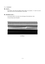
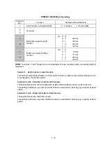
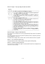
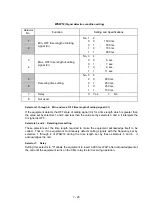
Selector 7:
Switching between pulse (DP) and tone (PB) dialing, by the function switch
This selector determines whether or not the dialing mode may be switched between the pulse (DP)
and tone (PB) dialing by using the function switch.
l
Selector 8:
Default dialing mode, pulse (DP) or tone (PB) dialing
This selector sets the default dialing mode (pulse dialing or tone dialing) which may be changed by
the function switch. If the user switches it with the function switch when selector 7 is set to "0," the
setting specified by this selector will also be switched automatically.
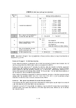
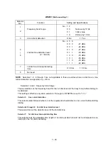
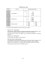
WSW02
(Tone signal setting
)
Selector
No.
Function
Setting and Specifications
1
2
Tone signal transmission time
length
No. 1 2
0 0
:
70 ms
0 1
:
80 ms
1 0
:
90 ms
1 1
:
100 ms
3
4
Min. pause in tone dialing
No. 3 4
0 0
:
70 ms
0 1
:
80 ms
1 0
:
90 ms
1 1
:
140 ms
5
|
8
Attenuator for pseudo ring
backtone to the line (selectable in
the range of 0-15 dB)
0: 0 dB
1: 8 dB
0: 0 dB
1: 4 dB
0: 0 dB
1: 2 dB
0: 0 dB
1: 1 dB
l
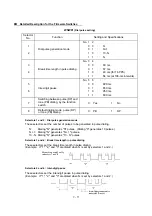
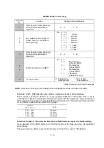
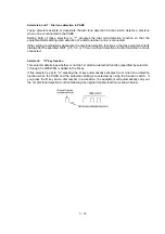
Selectors 1 through 4: Tone signal transmission time length and Min. pause in tone dialing
These selectors set the tone signal transmission time length and minimum pause in tone dialing.
(Example: If "1," "2," "3," "4," and "5" are dialed.)
l
Selectors 5 through 8: Attenuator for pseudo ring backtone to the line
These selectors are used to adjust the sound level of beep generated as a ring backtone in the F/T
mode or as a signal during remote control operation or at the start of ICM recording.
Setting two or more selectors to “1” produces addition of attenuation assigned to each selector.
Summary of Contents for FAX-8650P
Page 1: ...FACSIMILE EQUIPMENT SERVICE MANUAL MODEL FAX3750 FAX 8650P MFC7750 ...
Page 5: ...CHAPTER I GENERAL DESCRIPTION ...
Page 12: ...CHAPTER II INSTALLATION ...
Page 13: ...CONTENTS 1 INSTALLING THE UPDATE DATA TO THE FACSIMILE EQUIPMENT II 1 ...
Page 16: ...CHAPTER III THEORY OF OPERATION ...
Page 18: ...III 1 1 OVERVIEW Not provided on the FAX 8650P ...
Page 28: ...III 11 Not provided on the FAX 8650P Location of Sensors and Actuators ...
Page 31: ...III 14 Main PCB Modem PCB ...
Page 36: ...CHAPTER IV DISASSEMBLY REASSEMBLY AND LUBRICATION ...
Page 42: ...IV 4 n n Disassembly Order Flow ...
Page 71: ...IV 33 1 Provided on the FAX 8650P 2 Not provided on the FAX 8650P ...
Page 72: ...IV 34 Setting up the main PCB after replacement ...
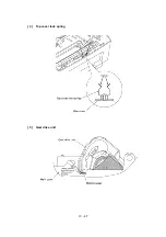
Page 84: ...IV 46 2 Control panel locks 3 Scanner frame ASSY and separation roller gear ...
Page 85: ...IV 47 4 Top cover lock spring 5 Gear drive unit ...
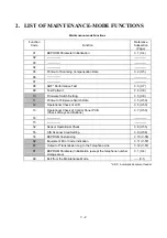
Page 86: ...CHAPTER V MAINTENANCE MODE ...
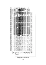
Page 93: ...V 6 Scanning Compensation Data List ...
Page 141: ...V 54 FAX3750 FAX 8650P MFC7750 Key Button Entry Order ...
Page 146: ...CHAPTER VI ERROR INDICATION AND TROUBLESHOOTING ...
Page 171: ...Oct 98 SM5X5303 Printed in Japan ...
Page 172: ...FAX3750 FAX 8650P MFC7750 Appendix 1 EEPROM Customizing Codes ...
Page 194: ......
Page 195: ......
Page 196: ......


