background image

 5-16 

Confidential


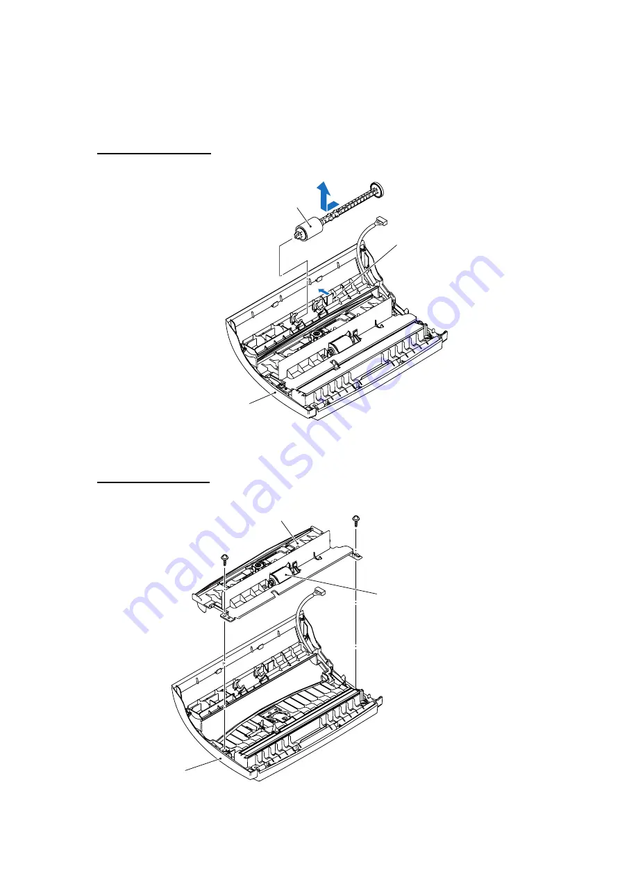
5.1.5  Disassembly of the Top Cover Sub ASSY 

(Paper separation roller, document chute ASSY, document separation roller, ADF parts, 
white-level reference film, control panel ASSY, and document rear sensor actuator) 

Paper separation roller 

(1)  Lightly press the lock arm, slide the paper separation roller to the left and lift it up. 

Paper


separation


roller

Top


cover


sub


ASSY


(placed


upside


down)

(Front)

Lock


arm


Reassembling Note:

  When mounting the paper separation roller, make sure that the panel-main 

harness (upper) has been routed on the top cover as shown 

on page 5-20


Document chute ASSY 

(2)  Remove the two screws and take the document chute ASSY out of the top cover. 

Document


chute


ASSY

Top


cover


(placed


upside


down)

(Front)

Document


separation


roller


Taptite, cup B M3x8 

Summary of Contents for FAX-545

Page 1: ...Confidential FACSIMILE EQUIPMENT SERVICE MANUAL MODELS FAX 575 FAX T102 T104 T106 FAX 817 827 837MC FAX 878 ...

Page 2: ...ication may be reproduced in any form or by any means without permission in writing from the publisher All product and company names mentioned in this manual are trademarks or registered trademarks of their respective holders Specifications are subject to change without notice ...

Page 3: ...ing mechanisms as well as the sensors actuators and control electronics It aids in understanding the basic principles of operation as well as locating defects for troubleshooting CHAPTER 4 TRANSFER OF DATA LEFT IN THE MACHINE TO BE SENT FOR REPAIR Describes how to transfer data left in the machine to be sent for repair The service personnel should instruct end users to follow the transfer procedur...

Page 4: ...ers Appendix 2 Firmware Installation Not applicable Appendix 3 Customizing Codes According to Shipping Destination Provides instructions on how to set up the customizing codes for the various preferences exclusively designed for each destination e g language Those codes are stored in the memory EEPROM mounted on the main PCB If the main PCB is replaced therefore you will need to set up the proper ...

Page 5: ... telephone line has been disconnected at the wall socket Never install telephone wiring during a lightning storm Never install a telephone socket in a wet location This product must be installed near an electrical socket that is easily accessible In case of emergencies you must disconnect the power cord from the electrical socket in order to shut off power completely If the machine becomes hot rel...

Page 6: ...ine SAVE THESE INSTRUCTIONS Choosing a location Place the fax machine on a flat stable surface that is free of vibration and shocks such as a desk Put the fax machine near a telephone socket and a standard grounded electrical socket Choose a location where the temperature remains between between 10 C 35 C Caution Avoid placing the fax machine in a high traffic area Do not place near heaters air co...

Page 7: ...Confidential CHAPTER 1 PARTS NAMES FUNCTIONS ...

Page 8: ...ter contains external views and names of components and describes their functions Information about the keys on the control panel is included to help you check operation or make adjustments CONTENTS 1 1 OUTLINE 1 1 1 2 CONTROL PANEL 1 3 1 3 COMPONENTS 1 9 ...

Page 9: ...1 1 Confidential 1 1 OUTLINE Front view FAX 575 FAX T102 FAX T104 FAX T106 FAX 817 FAX 827 FAX 837MC FAX 878 ...

Page 10: ...nnect the handset to the fax machine 5 Paper wire extension Supports the paper in the paper tray 6 Document support Supports documents in the ADF 7 Paper tray Load paper here 8 Paper guides Press and slide to fit the document width 9 Control panel Use the keys and display to control the fax machine 10 Cover open lever To open the top cover lift this lever 11 AC power connector Plug in the power co...

Page 11: ...transfer a call to another extension when it is connected to a PABX 2 Play Record 5 Speaker Phone Lets you listen to voice messages and print fax messages stored in memory This also lets you record telephone calls Lets you speak to another party without lifting the handset 3 Dial Pad 6 Redial Pause Use these keys to dial telephone and fax numbers and as a keyboard for entering information into the...

Page 12: ...ce or fax messages in the memory 10 Stop Exit 17 Navigation Keys Stops a fax cancels an operation or exits from the menu 11 Fax Start Starts an operation such as sending a fax 12 Copy Reports With a document in the ADF Makes a copy Without a document in the ADF Lets you access the Reports menu 13 One Touch Dial Keys These keys give you instant access to previously stored Quick Dial numbers Menu Se...

Page 13: ...dial telephone and fax numbers and as a keyboard for entering information into the fax machine The key lets you temporarily switch the dialing type during a telephone call from PULSE to TONE Redials the last number you called It also inserts a pause in Quick Dial numbers 3 R 6 Search Mute Use this key to gain access to an outside line and or to recall the operator or transfer a call to another ext...

Page 14: ... operations Lets you access the menu to program and store your settings in the fax machine or Press to scroll forward or backward to see a menu selection OR You can press these keys to adjust the beeper ring or speaker volume or Press to scroll through the menus and options You can also use these keys to do a numerical search for stored numbers 11 Copy Reports With document in the ADF Makes a copy...

Page 15: ...elephone call from PULSE to TONE not available in New Zealand 2 One Touch Keys 5 Recall These 6 keys give you instant access to 12 previously stored Quick Dial numbers Use this key to gain access to an outside line for Australia and New Zealand only and or to recall the operator or transfer a call to another extension when it is connected to a PABX 3 Shift 6 Search Mute To access One Touch numbers...

Page 16: ...0 Fax Start Starts an operation such as sending a fax Menu Set The same key is used for menu and set operations Lets you access the menu to program and store your settings in the fax machine or Press to scroll forward or backward to see a menu selection OR You can press these keys to adjust the beeper ring or speaker volume or Press to scroll through the menus and options You can also use these ke...

Page 17: ...1 9 Confidential 1 3 COMPONENTS The machine consists of the following major components 1 Not provided on the FAX T102 2 FAX T102 3 FAX 837MC FAX T106 ...

Page 18: ...Confidential CHAPTER 2 SPECIFICATIONS ...

Page 19: ...s chapter lists the specifications of each model which enables you to make a comparison of different models CONTENTS 2 1 GENERAL 2 1 2 1 1 General Specifications 2 1 2 1 2 Paper Specifications for the Paper Tray 2 2 2 2 SPECIFICATIONS LIST 2 3 ...

Page 20: ...characters x 1 Line Operating Environment Temperature 5 35 C Humidity 20 80 Best Print Quality 20 30 C Power Source 220 240 VAC 50 60 Hz Power Consumption Standby Under 4 4 watts FAX T104 Under 4 8 watts FAX T106 Under 4 0 watts FAX 878 Operating under 160 watts Dimensions W x D x H 11 9 x 7 4 x 5 4 inches 302 x 188 x 138 mm with paper tray and paper wire extension 11 9 x 10 5 x 13 4 inches 302 x ...

Page 21: ...aper specifications for the paper tray Weight 17 to 24 lb 64 to 90 g m2 Thickness 0 003 to 0 0039 in 0 08 to 0 10 mm Recommended paper Xerox 4200DP 20lb The fax machine can only scan an image 208 mm wide regardless of how wide the paper is Do not use cardboard newspaper or fabric Do not use paper that is extremely shiny or highly textured that was previously printed by a printer that cannot be arr...

Page 22: ...220 240V AC 50 60Hz 220 240V AC 50 60Hz Power Consumption Standby under 4 8 watts under 4 4 watts under 4 8 watts Power Consumption Peak under 160 watts under 160 watts under 160 watts Power Save N A N A N A Sleep Mode N A N A N A Energy Star Compliant USA only Yes N A N A Melody Alarm ASIA MC TAD only N A N A N A Remote Maintenance N A N A N A TELEPHONE Handset Yes Yes Base No w o Yes Off Hook Al...

Page 23: ... N A LIST REPORT Activity Report Journal Report Yes Up to 30 in Report key Yes Up to 30 in Report key Yes Up to 30 in Report key Transmission Verification Report Yes in Report key Yes in Report key Yes in Report key Coverpage Yes Yes Yes Help List Yes in Report key Yes in Report key Yes in Report key Call Back Message Yes Yes Yes Caller ID List Yes Caller ID key Yes Yes Quick Dial List Yes in Repo...

Page 24: ... 220 240V AC 50 60Hz Power Consumption Standby under 4 4 watts under 4 8 watts under 4 0 watts Power Consumption Peak under 160 watts under 160 watts under 160 watts Power Save N A N A N A Sleep Mode N A N A N A Energy Star Compliant USA only N A N A N A Melody Alarm ASIA MC TAD only N A Yes N A Remote Maintenance N A N A N A TELEPHONE Handset Yes Yes Yes Off Hook Alarm N A N A N A Chain Dialing N...

Page 25: ...ARL NZ LIST REPORT Activity Report Journal Report Yes Up to 30 in Report key Yes Up to 30 in Report key Yes Up to 30 in Report key Transmission Verification Report Yes in Report key Yes in Report key Yes in Report key Coverpage N A 817 Yes 827 Yes Yes Help List Yes in Report key Yes in Report key Yes in Report key Call Back Message N A 817 Yes 827 Yes Yes Caller ID List Yes Yes Yes Quick Dial List...

Page 26: ...Confidential CHAPTER 3 THEORY OF OPERATION ...

Page 27: ...lectronics It aids in understanding the basic principles of operation as well as locating defects for troubleshooting CONTENTS 3 1 OVERVIEW 3 1 3 2 MECHANICAL COMPONENTS 3 2 3 2 1 Scanning Mechanism 3 3 3 2 2 Printing Mechanism 3 3 3 2 3 Power Transmission Switching Mechanism 3 4 3 2 4 Sensors and Actuators 3 5 3 3 CONTROL ELECTRONICS 3 7 3 3 1 Components 3 7 ...

Page 28: ...3 1 Confidential 3 1 OVERVIEW 1 Not provided on the FAX T102 2 Model with battery FAX T106 FAX 837MC ...

Page 29: ...isms and uses a single motor and various sensors Scanning Mechanism Document feeding ejecting mechanism Document scanning mechanism Printing Mechanism Paper feeding and registration mechanism Printing and paper ejecting mechanism Power Transmission Switching Mechanism Sensors and Actuators ...

Page 30: ...ing the light input to picture element data output and CIS glass on which a document advances When the document passes between the white level reference film attached to the top cover and the CIS glass it is scanned 3 2 2 Printing Mechanism The printing mechanism consists of the paper tray sheet feeder SF paper separation roller platen thermal recording head paper ejection roller and sensors For d...

Page 31: ...chine to function in five operation modes scanning paper feeding recording paper ejecting and copying modes To switch to a particular mode the motor rotates in the reverse direction If the switching cam of the planet gear ASSY turns on the cam switch the motor further rotates by the specified number of pulses to locate the planet gear ASSY in the particular mode position Then the motor rotates in ...

Page 32: ...t is placed on the handset mount The registration sensor detects the leading and trailing edges of paper for use in determining registration timing and detecting paper jams The ribbon switch detects whether the print cartridge ink ribbon is loaded The cam switch detects the drive positions of the switching cam in the drive unit The document rear sensor and registration sensor are a photointerrupte...

Page 33: ...3 6 Confidential Not provided on the FAX T102 Sensors and Actuators Locations ...

Page 34: ... 3 1 Components The following illustration shows the hardware components for this machine The corresponding connection diagram appears in Appendix 5 0 1 234 51 2 6 7 0 8 9 9 1 Not provided on the FAX T102 2 FAX837MC FAX T106 Machine Components ...

Page 35: ...Confidential CHAPTER 4 TRANSFER OF DATA LEFT IN THE MACHINE TO BE SENT FOR REPAIR ...

Page 36: ...to be sent for repair The service personnel should instruct end users to follow the transfer procedure given in this chapter if the machine at the user site cannot print received data due to the printing mechanism defective End users can transfer received data to another machine to prevent data loss CONTENTS 4 1 TRANSFERRING RECEIVED FAX DATA 4 1 ...

Page 37: ...ired that has received data in the memory to the telephone line 2 Switch the machine on 3 Press the Menu Set Fax Start Menu Set 5 and 3 keys in this order to access user accessible functions of the maintenance mode The FAX TRANSFER appears on the LCD 4 To transfer received files press the 1 key The 1 FAX TRANSFER appears Note that if there is no received file the NO DOCUMENTS appears 5 To transfer...

Page 38: ...Confidential CHAPTER 5 DISASSEMBLY REASSEMBLY AND LUBRICATION ...

Page 39: ...ok Switch Actuator and Cover Open Sensor Actuator 5 5 5 1 2 Cover Stopper Link and Top Cover ASSY 5 7 5 1 3 Disassembly of the Top Cover ASSY Separation roller gear 29 paper chute ASSY and top cover sub ASSY 5 9 5 1 4 Disassembly of the Paper Chute ASSY Chute film sheet feeder parts paper ejection roller ASSY registration sensor actuator lock bar levers and platen 5 11 5 1 5 Disassembly of the Top...

Page 40: ...Confidential 5 1 14 Ribbon Switch and Grounding Plate 5 38 5 1 15 Speaker 5 39 5 1 16 Recorder Frame 5 40 5 1 17 Routing of the Harnesses 5 41 5 2 LUBRICATION 5 42 ...

Page 41: ...of the machine to discharge static electricity charged in your body When transporting PCBs be sure to wrap them in conductive sheets such as aluminum foil When replacing the head carriage unit put on a grounding wrist band and perform the job on a static mat Also take care not to touch the conductor sections on the flat cables 5 Be sure to reinsert self tapping screws correctly if removed 6 Tighte...

Page 42: ...r PCB Taptite cup B M3x10 1 0 49 0 2 5 2 Bottom plate Taptite cup B M3x10 5 0 5 0 2 5 2 Taptite cup S M3x6 1 0 7 0 2 7 2 Grounding wire Screw pan washer M4x7DB 1 0 7 0 1 7 1 Drive unit Taptite cup B M3x10 2 0 5 0 2 5 2 Motor chassis Taptite cup B M3x8 2 0 7 0 1 7 1 Drive motor Taptite cup S M3x6 1 0 7 0 1 7 1 CIS holder Taptite bind B M3x8 2 0 39 0 2 4 2 NCU PS enclosure Taptite cup B M3x10 1 0 49...

Page 43: ...ge Not provided on the FAX T102 Paper wire extension Print cartridge Handset Telephone line cord Power cord Paper tray Document wire How to Access the Object Component On the next page is a disassembly flowchart which helps you access the object components To remove the drive unit for example first find it on the flowchart and note its number in this case To access it you need to remove all the pa...

Page 44: ...5 4 Confidential Disassembly Flowchart 0 1 2 3 3 2 4 5 0 6 7 2 7 2 3 8 3 3 1 2 3 5 77 6 5 0 2 2 4 2 9 2 9 2 2 2 2 2 0 5 3 5 77 5 0 9 ...

Page 45: ... 1 Open the top cover by lifting the cover open lever 2 Press the inside of the handset mount or dummy mount to unlatch and twist it in the direction of the arrow shown below Cover open lever Top cover Handset mount Dummy mount Latch Hooks Setting the handset mount dummy mount back into place Handset mount Dummy mount Main cover Main cover ...

Page 46: ...omes off Cover open sensor actuator Actuator spring Actuator support Actuator support Handset mount Actuator spring Hook switch actuator Reassembling Notes When setting the handset mount dummy mount back into place first fit the two hooks provided on the rear end of the handset mount dummy mount in the main cover arrow and then push down the handset mount dummy mount arrow until it snaps into plac...

Page 47: ...SY 1 Remove the screw from the cover stopper link Pull the link outwards to release it from the top cover ASSY and then turn it to the front and release it from the boss on the main cover Top cover ASSY Main cover Cover stopper link Boss Taptite pan B M4x6D10 ...

Page 48: ...harness upper Relay connector Panel main harness lower Main cover Routing the panel main harness lower Cable guide Panel main harness lower Reassembling Notes Be sure to route the panel main harness lower through the cable guide provided on the main cover as shown above When mounting the cover stopper link support the top cover ASSY with your left hand and secure the link with the screw ...

Page 49: ...he three screws from the paper chute ASSY 4 Lift the rear end of the paper chute ASSY to release the tab from the top cover and take the panel main harness upper out of the paper chute ASSY Then remove the ASSY Paper chute ASSY Tab Top cover sub ASSY placed upside down Front Lock arm Panel main harness upper Separation roller gear 29 Panel main harness upper Taking the panel main harness upper out...

Page 50: ...on roller is correctly positioned that is its shorter shaft faces to the left and its left end is in contact with the rib on the document chute ASSY 5 Lightly press the lock arm insert the separation roller gear 29 and fit it over the right end of the document separation roller shaft Paper chute ASSY Tab Fitting the square openings over the paper chute supports Paper chute ASSY Paper chute support...

Page 51: ...te film from the paper chute ASSY only when it should be replaced Attaching a new chute film Paper chute ASSY placed upside down Platen Front Chute film Ribs Reassembling Note Once removed the chute film will become unusable and a new one will have to be put back in Reassembling Note When attaching a new chute film to the chute cover ASSY bring its rear edge into contact with the ribs as shown bel...

Page 52: ...eaf spring with a flat screwdriver taking care not to deform it Paper chute ASSY Bent section SF leaf spring Rear Lock arm Flat screwdriver SF leaf spring Lock arm Mounting the SF leaf spring with a flat screwdriver Removing the SF leaf spring Flat screwdriver Reassembling Note When mounting the SF leaf spring be sure to push down its bent section with a flat screwdriver until the lock arm catches...

Page 53: ...he paper ejection roller ASSY Also remove gear 10 NOTE Take care not to lose gear 10 SF coil spring Rear Paper chute ASSY Gear 10 Paper ejection roller ASSY Lock arm SF separation pad support SF separation pad SF plate SF separation film 7 Remove the gear 22 and clutch spring from the paper ejection roller ASSY Fitting the end of the clutch spring into the slit between flanges Gear 22 Paper ejecti...

Page 54: ...Lightly press the lock arm lift up the left end of the registration sensor actuator and take it out to the right 9 Remove gears 24 by releasing their latches Paper chute ASSY Registration sensor actuator Lock arm Rear Latches Gears 24 Registration sensor actuator ...

Page 55: ...spring Lock spring Lock lever R dark gray Lock bar Front Platen Latch Lock lever L white Paper chute ASSY placed upside down Lock lever R dark gray Reassembling Note When mounting the lock lever R set the lock spring as shown above Platen 13 Release the latch of the platen gear and remove the gear and bushing L 14 Remove pawl bushing R and take the platen out of the paper chute ASSY Platen Pawl bu...

Page 56: ... paper separation roller to the left and lift it up Paper separation roller Top cover sub ASSY placed upside down Front Lock arm Reassembling Note When mounting the paper separation roller make sure that the panel main harness upper has been routed on the top cover as shown on page 5 20 Document chute ASSY 2 Remove the two screws and take the document chute ASSY out of the top cover Document chute...

Page 57: ...d on the document chute ASSY Reassembling Note 1 Before mounting the document chute ASSY be sure to slide the paper guides outwards to the A4 size position Paper guides Document chute ASSY Top cover placed upside down Front Document chute ASSY The document separation roller shaft should be in contact with this rib on the document chute ASSY Separation roller gear 29 Document separation roller Reas...

Page 58: ...ocument chute Document separation roller ADF parts 5 Remove the screw and disassemble the ADF parts as shown below ADF parts ADF leaf spring Separation rubber ADF holder ADF spring Top cover placed upside down Front Setting the separation rubber into place Separation rubber Wrong Correct Reassembling Note Make sure that the separation rubber is fitted over the ADF holder correctly Taptite pan B M3...

Page 59: ...he left and rear edges of the white level reference film with this rib Front Top cover placed upside down Front White level reference film Reassembling Note Once removed the white level reference film will become unusable and a new one will have to be put back in Reassembling Note When attaching a new white level reference film align the left and rear edges with the rib provided on the top cover ...

Page 60: ...eassembling Note When setting the document rear sensor actuator back into place be sure to fit the actuator s tab in the slot between the ribs Reassembling Note When assembling the top cover and the control panel ASSY pass the panel main harness upper through the square opening provided in the top cover and fit the two tabs on the top cover under the corresponding corner ribs Reassembling Note Rou...

Page 61: ...ct the LCD flat cable NOTE After disconnecting the flat cable s check that each cable is not damaged at its end or short circuited When connecting the flat cable s do not insert it at an angle After insertion check that the cable is not at angle 3 FAX 837MC FAX T106 Take the microphone from the control panel 4 Unlatch the control panel PCB and remove the PCB Panel main harness upper Control panel ...

Page 62: ...cable gently Lock arm LCD LCD flat cable Lock arm Reassembling Notes Before setting the LCD back to the control panel wipe fingerprints or dust off the LCD surface and control panel window with a soft cloth A new LCD is covered with a protection sheet Before setting it remove the protection sheet ...

Page 63: ...nnector and disconnect the LCD flat cable 3 Unlatch the control panel PCB and remove the PCB NOTE After disconnecting the flat cable s check that each cable is not damaged at its end or short circuited When connecting the flat cable s do not insert it at an angle After insertion check that the cable is not at angle ...

Page 64: ...lling the LCD flat cable gently Reassembling Notes Before setting the LCD back to the control panel wipe fingerprints or dust off the LCD surface and control panel window with a soft cloth A new LCD is covered with a protection sheet Before setting it remove the protection sheet ...

Page 65: ... 7 Sensor PCB 1 Remove the screw from the sensor PCB 2 Disconnect the sensor main harness from the sensor PCB 3 Unlatch the sensor PCB from the main cover Sensor PCB Sensor main harness Main cover Latch Taptite cup B M3x10 ...

Page 66: ...he two head main harnesses red and white from the recording head ASSY and lift up the ASSY 3 Remove the three head springs Recording head ASSY Tab Tab Head springs Head main harness white Main cover Lock arm Head spring Recording head ASSY Lock arm Recorder frame Head main harness red Viewed from the front Recorder frame Viewed from the left Reassembling Notes After mounting the recording head ASS...

Page 67: ... and release the grounding wire screw c Grounding wire Main cover placed upside down Routing the grounding wire through this cutout Front Bottom plate a a a a b a Inside of the bottom plate Rear Securing the grounding wire c a Taptite cup B M3x10 b Taptite cup S M3x6 c Screw pan washer M4x7DB Reassembling Notes Secure the grounding wire to the bottom plate at the angle shown above ...

Page 68: ...rom the main PCB 2 Turn the main cover rightside up 3 Remove the two screws and lift the drive unit up and out of the main cover Drive unit Cam switch harness Motor harness Main cover Main PCB Viewed from the bottom Cam switch harness Motor harness Opening provided in the main cover Taptite cup B M3x10 ...

Page 69: ...screw e to release the drive motor from the motor chassis 6 Unlatch the cam switch Drive gear frame e d d Drive motor Motor chassis Cam switch Latches Bosses on the drive gear frame Drive motor Bosses on the drive gear frame Motor chassis d Taptite cup B M3x8 e Taptite cup S M3x6 ...

Page 70: ... side as shown on the previous page After mounting the motor chassis route the motor harness as shown below Drive motor Cam switch ASSY Motor harness Cam switch harness Cable guides Drive gear frame Guide bosses When assembling the motor chassis and drive gear frame together does not mesh gears smoothly rotate the planet gear ASSY clockwise and counterclockwise as shown below Drive motor Motor gea...

Page 71: ...ction roller gear from the left end of the document ejection roller and then take the roller out of the main cover 3 Remove the pinch rollers and their shaft 4 Remove the pinch roller springs Document ejection roller Ejection roller gear Main cover Pinch roller springs Pinch rollers Pinch roller shaft Pawl bushing Reassembling Notes When mounting the pinch rollers be sure to face the flange sides ...

Page 72: ... from the main PCB NOTE The CIS main harness passes through a ferrite core one turn Take care not to lose the ferrite core When replacing the CIS main harness it is necessary to remove the ferrite core and attach it to a new harness 3 Disconnect the battery harness from the main PCB Main PCB CIS main harness 7 pin Battery harness 2 pin ...

Page 73: ... 7 Remove the CIS springs 8 Remove the battery ASSY DANGER Explosion hazard Never disassemble or recharge the battery Explosion hazard Never dispose of the battery in fire WARNING There is a danger of explosion if the battery is incorrectly replaced When replacing the battery use the spare part authorized by Brother Industries Batteries used should be disposed of in accordance with the local codes...

Page 74: ...5 34 Confidential 9 Take the CIS holders off the CIS unit by removing the screws CIS unit CIS holder CIS holder Taptite bind B M3x8 ...

Page 75: ...ake it from the cable guides on the NCU PS enclosure 3 Remove the screw from the NCU PS enclosure 4 Lightly pull up the power supply PCB and NCU PCB to disconnect them from the main PCB 5 Lift the NCU PS enclosure up and out of the main cover NCU PCB Power supply PCB Cable guides Head main harness red Main cover placed upside down Main PCB NCU PS enclosure Taptite cup B M3x10 ...

Page 76: ...e 8 Disconnect the following harnesses from the main PCB Head main harness white Sensor main harness Ribbon switch harness Speaker harness Battery harness FAX T106 FAX 837MC 9 Release the main PCB from the three latches on the main cover Main PCB Head main harness white Head main harness red Main cover placed upside down 3 latches Speaker harness Sensor main harness Ribbon switch harness Taptite c...

Page 77: ...When mounting the power inlet to the NCU PS enclosure face the grounding wire side down See the illustration on the previous page After mounting the NCU PS enclosure route the head main harness red through the cable guides on the NCU PS enclosure Refer to Section 5 1 17 ...

Page 78: ...tweezers into the smallest hole there are three square holes to unhook the ribbon switch 3 Turn the main cover upside down 4 Remove the screw and lift up the grounding plate Ribbon switch Grounding plate Main cover placed upside down Spring hook Smallest square hole Ribbon switch Main cover rightside up Taptite cup S M3x6 ...

Page 79: ...ll the speaker and its spring up and out of the main cover Speaker spring Speaker Main cover Cutout Speaker harness Orienting the speaker and its harness Speaker Reassembling Notes When mounting the speaker to the main cover orient the speaker and its harness as shown above ...

Page 80: ...der frame and lift it up and out of the main cover 2 Remove the head main harnesses red and white Reassembling Notes Before mounting the recorder frame check that the top is free from scratches or burrs Those on the top will affect the quality of printed images Taptite cup B M3x8 ...

Page 81: ...5 41 Confidential 5 1 17 Routing of the Harnesses 0 11 ...

Page 82: ...ion points as shown below Lubricant type Manufacturer Lubrication points Lubricant amount ZZG 206 Sankei kagaku co Ltd Paper chute ASSY 2 mm dia ball Paper chute ASSY Apply a 2 mm dia ball of grease ZZG 206 to each of the following lubrication points 2 mm dia ball of grease ZZG 206 ...

Page 83: ...Confidential CHAPTER 6 ADJUSTMENTS AND UPDATING OF SETTINGS REQUIRED AFTER PARTS REPLACEMENT ...

Page 84: ...er details adjustments and updating of settings which are required if the main PCB has been replaced CONTENTS 6 1 IF YOU REPLACE THE MAIN PCB 6 1 1 EEPROM customizing 6 1 2 EEPROM parameter initialization 6 2 3 ID code entry to the EEPROM 6 2 4 CIS scanner area setting 6 2 5 Document draw adjustment 6 2 ...

Page 85: ... the power is on next time z In case that customer s specification is obvious and EEPROM customizing is set in advance as a service 1 Turn the machine on The SET COUNTRY and PRESS SET KEY appear alternately on the LCD 2 Press the Menu Set key PAN NORDIC model The NORWAY and SELECT SET appear alternately OCEANIA model The AUSTRALIA and SELECT SET appear alternately EAST EUROPE model The CZECHO and ...

Page 86: ...fer to Chapter 8 Section 8 4 1 Function 01 91 3 ID code entry to the EEPROM Refer to Chapter 8 Section 8 4 14 Function 80 4 CIS scanner area setting Refer to Chapter 8 Section 8 4 12 Function 55 5 Document draw adjustment Refer to Chapter 8 Section 8 4 17 ...

Page 87: ...Confidential CHAPTER 7 CLEANING This chapter is not applicable to FAX models covered by this manual ...

Page 88: ...Confidential CHAPTER 8 MAINTENANCE MODE ...

Page 89: ...tialization Function code 01 91 8 4 8 4 2 Printout of Scanning Compensation Data Function code 05 8 5 8 4 3 ADF Performance Test Function code 08 8 7 8 4 4 Test Pattern 1 Function code 09 8 8 8 4 5 Firmware Switch Setting and Printout Function codes 10 and 11 8 9 8 4 6 Operational Check of LCD Function code 12 8 12 8 4 7 Operational Check of Control Panel PCB Function code 13 8 13 8 4 8 Sensor Ope...

Page 90: ...dicating that it is placed in the initial stage of the maintenance mode a mode in which the machine is ready to accept entry from the keys To select one of the maintenance mode functions listed in Section 8 2 enter the corresponding 2 digit function code with the numerical keys on the control panel The details of each maintenance mode function are described in Section 8 4 NOTES To exit from the ma...

Page 91: ...Panel PCB Check of Keys 8 4 7 8 13 32 Sensor Operational Check 8 4 8 8 15 45 Handset Transmitter Volume Control 8 4 9 8 16 53 Transfer of Received FAX Data and or Equipment s Log 8 4 10 8 17 54 Fine Adjustment of Scanning Start End Position 8 4 11 8 18 55 CIS Scanner Area Setting 8 4 12 8 19 74 EEPROM Customizing 8 4 13 8 19 80 ID Code Entry to the EEPROM 8 4 14 8 21 82 Equipment Error Code Indica...

Page 92: ...s order The 0 appears on the LCD 2 Enter the desired function code 10 11 12 45 53 80 82 87 or 91 with the numerical keys For function code 10 access the desired firmware switch according to the operating procedure described in Appendix 4 3 To switch the machine back to the standby state press the Stop Exit key When each of the user accessible functions is completed the machine automatically return...

Page 93: ...ivity report settings Distinctive ringing patterns registered Cover page comment number These will be initialized Station ID data Cover page custom comments Remote access code FAX forwarding TX lock password Telephone function registration One touch dialing Speed dialing Group dialing All of these will be initialized These will not be initialized EEPROM customizing code 4 digit ID code This will n...

Page 94: ...data and takes in the scanning compensation reference data 1 Press the 0 and 5 keys in this order in the initial stage of the maintenance mode The WHITE LEVEL 1 will appear on the LCD 2 The machine prints out the scanning compensation data list containing the following a White level data 208 bytes b Black level data 1 byte c White level data for compensation operation of background color 100 bytes...

Page 95: ...8 6 Confidential Scanning Compensation Data List a b c d e f g h i j k ...

Page 96: ...s the 1st document and displays COPY P 01 STD on the LCD ii feeds in and out the 2nd through 4th documents while counting without copying them as the LCD shows the corresponding count iii copies the 5th document and displays COPY P 05 STD on the LCD iv feeds in and out the 6th through 9th documents while counting without copying them as the LCD shows the corresponding count and v copies the 10th d...

Page 97: ...like the copying function prints out test pattern 1 to allow the service personnel to check for record data missing or print quality Operating Procedure Press the 0 and 9 keys in this order in the initial stage of the maintenance mode The figure below shows test pattern 1 Test Pattern ...

Page 98: ...X mode setting WSW04 TRANSFER facility setting WSW05 1st dial tone and busy tone detection WSW06 Pause key setting and 2nd dial tone detection WSW07 Dial tone setting 1 WSW08 Dial tone setting 2 WSW09 Protocol definition 1 WSW10 Protocol definition 2 WSW11 Busy tone setting WSW12 Signal detection condition setting WSW13 Modem setting WSW14 AUTO ANS facility setting WSW15 REDIAL facility setting WS...

Page 99: ...Press the Menu Set key This operation saves the newly entered selector values onto the EEPROM and readies the machine for accepting a firmware switch number 6 Repeat steps 2 through 5 until the modification for the desired firmware switches is completed 7 Press the Menu Set or Stop Exit key to return the machine to the initial stage of the maintenance mode NOTES To cancel this operation and return...

Page 100: ... firmware switches Operating Procedure 1 Press the 1 key twice in the initial stage of the maintenance mode The PRINTING will appear on the LCD 2 The machine prints out the configuration list as shown in the figure below 3 Upon completion of printing the machine returns to the initial stage of the maintenance mode Configuration List ...

Page 101: ...eys in this order in the initial stage of the maintenance mode The LCD shows the screen given at right 2 Press the Fax Start key Each time you press the Fax Start key the LCD cycles through the displays shown at right 3 Press the Stop Exit key or no keys for one minute The OK START NG KEY appears on the LCD 4 Press the Fax Start key The machine returns to the initial stage of the maintenance mode ...

Page 102: ...rect by referring to the illustration below If a key is pressed out of order the machine beeps and displays the INVALID OPERATE on the LCD To return to the status ready to accept key entry for operational check press the Stop Exit key 3 After the last number key is pressed the machine beeps and returns to the initial stage of the maintenance mode To terminate this operation press the Stop Exit key...

Page 103: ... of the keys names in the FAX T102 FAX 575 FAX 827 FAX 817 are different from the FAX T104 but the layout of the keys is the same Please follow the instruction below to operate Key Entry Order 2 FAX 878 The illustration below is FAX 878 Please follow the instruction below to operate Key Entry Order 3 ...

Page 104: ...is the relationship between the LCD indication sensor name and sensing status LCD Sensors Sensing status FRE Document front and rear sensors No document detected RC Cover sensor Control panel ASSY closed PH Registration sensor Recording paper loaded RX Ribbon sensor Ribbon cartridge loaded CH Cam switch in the drive unit Switching cam switch ON HK Hook switch On hook state The FAX T102 has no hook...

Page 105: ... off High volume Operating Procedure 1 Press the 4 and 5 keys in this order in the initial stage of the maintenance mode The ETC MAINTE appear on the LCD 2 Press the 2 and 1 keys The HANDSET LEV OFF and SELECT SET appear alternately on the LCD indicating that the attenuator is off and the transmitter volume is High 3 Use the or key to display the HANDSET LEV ON and SELECT SET alternately indicatin...

Page 106: ...is order in the initial stage of the maintenance mode The FAX TRANSFER appears on the LCD 2 To transfer received files press the 1 key The 1 FAX_TRANSFER appears Note that if there is no received file the NO DOCUMENTS appears 3 To transfer the activity report only press the 2 key The 2 REPORT_TRANS appears 4 To check the number of received files press the 3 key The 3 NO OF JOBS appears on the LCD ...

Page 107: ...on value as shown at right 2 Press the Fax Start key Each time you press the Fax Start key the LCD cycles through the displays shown at right That is pressing this key cycles through the correction values mm as shown below 3 To stop this operation press the Stop Exit key The machine beeps for one second and returns to the initial stage of the maintenance mode NOTE The relationship between the scan...

Page 108: ...OM according to language function settings and firmware switch settings Customizing codes come with the ROM update information provided by Brother Industries See Appendix 3 NOTE If you replace the main PCB be sure to carry out this procedure Operating Procedure 1 Press the 7 and 4 keys in this order in the initial stage of the maintenance mode The current customizing code e g 2004 in the case of F...

Page 109: ...40 2025 2048 FAX 837MC 2040 2048 FAX 878 2040 2020 Destination Switzerland Austria Netherlands Spain Portugal UK General FAX 575 FAX T102 2010 2014 FAX T104 2010 2014 2009 2015 2018 2004 FAX T106 2010 2014 2009 2015 2018 2004 FAX 817 FAX 827 FAX 837MC FAX 878 Destination Belgium Ireland Italy Pan Nordic Norway Finland Denmark Sweden East Europe Czech Hungary Poland Romania Bulgaria Other FAX 575 F...

Page 110: ...4 7 and 5 keys in this order The LCD switches to the edit mode showing a cursor 3 Enter the serial number given on the bottom plate using the and keys Alphabets and numerals are assigned to the keys as listed below 0 key 0 1 key 1 2 key 2 A B C 3 key 3 D E F 4 key 4 G H I 5 key 5 J K L 6 key 6 M N O 7 key 7 P Q R S 8 key 8 T U V 9 key 9 W X Y Z key key 4 Press the Menu Set key The machine displays...

Page 111: ... transmission to the telephone line It allows the service personnel to receive the transmission log of the user s machine at a remote location and use it for analyzing problems arising in the user s machine Operating Procedure 1 If the user s machine has a transmission related problem call the user s machine at a remote location from your machine 2 If the line is connected have the user perform th...

Page 112: ...t to the scanning start position While drawing it in the machine counts patterns on the chart to determine the amount of draw Upon completion of normal counting the machine shows the message COPY P 01 SUP on the LCD and begins copying the TC 027 chart The message REAR SENSOR IS ADJUSTED and the copied image will be printed out on recording paper as shown below If any error occurs during counting t...

Page 113: ...Confidential CHAPTER 9 ERROR INDICATION AND TROUBLESHOOTING ...

Page 114: ...related troubleshooting procedures This will help service personnel pinpoint and repair defective components CONTENTS 9 1 ERROR INDICATION 9 1 9 1 1 Equipment Errors 9 1 1 Error messages appearing on the LCD 9 1 2 Error codes contained in MACHINE ERROR X X messages 9 4 9 1 2 Communications Errors 9 9 9 2 TROUBLESHOOTING 9 16 9 2 1 Introduction 9 16 9 2 2 Precautions 9 16 9 2 3 Checking prior to Tr...

Page 115: ...ns list 9 1 1 Equipment Errors If an equipment error occurs the facsimile equipment emits an audible alarm continuous beeping for approximately 4 seconds and shows the error message on the LCD For the error messages see 1 below As one of the error messages MACHINE ERROR _ _ includes an error code which indicates the detailed error causes listed in 2 To display an error code for the other latest er...

Page 116: ...9 2 Confidential ...

Page 117: ...9 3 Confidential ...

Page 118: ...Head home position error Main PCB defective Replace main PCB Out of recording paper Load recording paper 82 No recording paper Recording paper is not set properly Set recording paper properly Foreign materials in the paper path Remove foreign materials 83 Recording paper jam The sheet feeder roller does not rotate correctly Replace paper ejection roller 84 Not used 85 Ink ribbon empty Out of ink r...

Page 119: ...ed Cover open sensor actuator not in place Set the cover open sensor actuator into place A1 Top cover opened Cover open sensor broken Replace the sensor PCB Document jam Remove the jammed document Document rear sensor actuator caught on the surrounding parts Correct the surrounding parts on which the actuator caught A2 Document length exceeding the scan limitation Document rear sensor broken Repla...

Page 120: ... line scan Main PCB defective Replace the main PCB A9 AA Not used AB AB displayed on the LCD in scanning test with test chart 027 This error code can appear only in the maintenance mode Cannot read black level data on test chart 027 even after the specified amount of document feeding after the registration sensor goes ON CIS defective Replace the CIS unit AC Less than 50 faulty of white level data...

Page 121: ...f serial number Customized code Serial number or customized code is not input Input the serial number function code 80 or customized code function code 74 E1 E5 Not used E6 Write error in EEPROM Main PCB defective Replace the main PCB E7 Not used CIS defective Replace the CIS unit E8 Data scanning error during transmission Main PCB defective Replace the main PCB E9 Not used Document front sensor a...

Page 122: ... of the STOP key in midway of scanning Illegal copying Copying a document longer than the recording paper or making an enlargement copy larger than the recording paper Recovery operation from the error state e g DOCUMENT JAM and CHECK PAPER error A304 In document ejecting caused by any of the following the document rear sensor sticks to OFF Depression of the STOP key in midway of scanning Illegal ...

Page 123: ... the LCD You can display those error codes in the maintenance mode Function code 82 If an equipment error occurs during communications they appear in the communications error lists 9 1 2 Communications Errors If a communications error occurs the machine emits an audible alarm intermittent beeping for approximately 4 seconds displays the corresponding error message and prints out the transmission v...

Page 124: ... station in sending 11 10 No tone detected after dialing 17 07 No response from the calling station in receiving 2 Command reception Code 1 Code 2 Causes 20 01 Unable to detect a flag field 20 02 Carrier was OFF for 200 ms or longer 20 05 A frame for 3 seconds or more received 20 06 CRC error in answerback 20 07 Undefined command received 20 08 Invalid command received 20 09 Command ignored once f...

Page 125: ...2 10 Remote terminal not equipped with password function or its password switch OFF 32 11 Remote terminal not equipped with or not ready for confidential mail box function 32 12 Remote terminal not equipped with or not ready for relay broadcasting function 32 14 The available memory space of the remote terminal is less than that required for reception of the confidential or relay broadcasting inst...

Page 126: ...ot allowed 40 06 Polled while not ready 40 07 No document to send when polled 40 10 Nation code or manufacturer code not coincident 40 13 Polled by any other manufacturers terminal while waiting for secure polling 40 17 Invalid resolution selected 5 Command reception checking the NSF and DIS after transmission of NSS and DCS Code 1 Code 2 Causes 50 01 Vertical resolution capability changed after c...

Page 127: ...onfidential 6 ID checking Code 1 Code 2 Causes 63 03 Polling ID not coincident 7 DCN reception Code 1 Code 2 Causes 74 DCN received 8 TCF transmission reception Code 1 Code 2 Causes 80 01 Fallback impossible ...

Page 128: ... fallback A0 11 Receive buffer empty 5 second time out A0 12 Receive buffer full during operation except receiving into memory A0 13 Decoding error continued on 500 lines A0 14 Decoding error continued for 10 seconds A0 15 Time out 5 seconds or more for one line transmission A0 16 RTC not found and carrier OFF signal detected for 6 seconds A0 17 RTC found but no command detected for 60 seconds AA ...

Page 129: ...mode Code 1 Code 2 Causes E0 01 Failed to detect 1300 Hz signal in burn in operation E0 02 Failed to detect PB signals in burn in operation 13 Equipment error Code 1 Code 2 Causes FF X X Equipment error For X X refer to Section 9 1 1 2 ...

Page 130: ...e electrical outlet when removing the covers and PCBs adjusting the mechanisms or conducting continuity testing with a circuit tester 2 When disconnecting the connectors do not pull the lead wires but hold the connector housings 3 z Before handling the PCBs touch a metal portion of the machine to discharge static electricity charged in your body z When repairing the PCBs handle them with extra car...

Page 131: ...een the main PCB and the control PCB Interfaces between the main PCB and power supply PCB LCD LCD flat cable Control panel PCB Power supply PCB Main PCB 2 Control panel inoperative Panel main harness between the main PCB and the control PCB Interfaces between the main PCB and power supply PCB Control panel PCB Rubber keypad Main PCB ...

Page 132: ...k Ordinary dialing function other than the speed and one touch dialing If it works normally check the main PCB if not refer to item 1 above 3 Speaker silent during on hook dialing Ordinary dialing function Pick up the handset and press the numerical keys If it works normally proceed to the following checks if not refer to item 1 above 4 Dial does not switch between tone and pulse Main PCB NCU PCB ...

Page 133: ...ment front sensor actuator Control panel PCB and its harness Main PCB 2 Document not fed ADF and its related sections Drive motor and its harness Document ejection roller and its related gears Cam switch and planetary gear train Main PCB 3 Recording paper not fed Sheet feeder SF and its related sections Drive motor and its harness Platen and its related gears Cam switch and planetary gear train Se...

Page 134: ...red and white Interface between the main PCB and power supply PCB Compression springs beneath the recording head Recording head Main PCB 2 White vertical streaks At the scanner At the recorder White level reference film stained CIS unit Recording head 3 All black At the scanner At the recorder CIS main harness CIS unit Head main harnesses red and white Recording head Main PCB 4 Black vertical stre...

Page 135: ...nner At the recorder Error code displayed Refer to Section 9 1 ERROR INDICATION in this chapter NCU PCB Main PCB Separation roller and its related sections Document ejection roller and its related gears Cam switch and planetary gear train Drive motor and its harness Main PCB Compression springs beneath the recording head Platen and its related gears Cam switch and planetary gear train Drive motor ...

Page 136: ...e of the following three beep codes Beep code In approx 2 second cycle of Defective device Beep code 1 LHLHLHLHm RAM Beep code 2 HLHLLHLHm EEPROM Beep code 3 HLHLHLHLm Program ROM H Beeps at 1 5 kHz for 0 1 second L Beeps at 1 2 kHz for 0 1 second m 0 5 second mute Between L and H H and L or L and L is a 0 1 second pause each ...

Page 137: ... FAX T102 T104 T106 FAX 817 827 837MC FAX 878 Appendix 1 Serial Numbering System This appendix shows the location of serial number labels put on some parts and lists the coding information pertaining to the serial numbers ...

Page 138: ...G SYSTEM Individual machines have a serial number label for the machine itself This section provides the coding information for the serial numbers Serial number label for the machine itself Location Serial number label on the bottom plate ...

Page 139: ...Confidential FAX 575 FAX T102 T104 T106 FAX 817 827 837MC FAX 878 Appendix 2 Firmware Installation This chapter is not applicable to FAX models covered by this manual ...

Page 140: ...the customizing codes for the various preferences exclusively designed for each destination e g language Those codes are stored in the memory EEPROM mounted on the main PCB If the main PCB is replaced therefore you will need to set up the proper customizing code with the machine in the maintenance mode Customizing codes come with the ROM release note provided by Brother Industries ...

Page 141: ... 575 A001 2002 2042 2036 FAX T102 FAX T104 FAX T106 FAX 817 FAX 827 2006 2027 FAX 837MC 2006 2027 FAX 878 2006 2027 Destination Asia Hong Kong Gulf China Turkey Russia France Germany FAX 575 FAX T102 2005 2003 FAX T104 2005 2003 FAX T106 2005 2003 FAX 817 2040 FAX 827 2140 2025 2048 FAX 837MC 2040 2048 FAX 878 2040 2020 Destination Switzerland Austria Netherlands Spain Portugal UK General FAX 575 ...

Page 142: ...mark Sweden East Europe Czech Hungary Poland Romania Bulgaria Other FAX 575 FAX T102 FAX T104 2008 2011 2016 2057 2007 2012 2013 2026 2087 2037 2038 2039 2088 2089 2086 FAX T106 2008 2011 2016 2057 2007 2012 2013 2026 2087 2037 2038 2039 2088 2089 2086 FAX 817 FAX 827 FAX 837MC FAX 878 ...

Page 143: ...tions of the firmware switches which can be divided into two groups one is for customizing preferences designed for the shipping destination as described in Appendix 3 and the other is for modifying preferences that match the machine to the environmental conditions Use the latter group if the machine malfunctions due to mismatching ...

Page 144: ... facility setting App 4 19 WSW16 Function setting 1 App 4 20 WSW17 Function setting 2 App 4 21 WSW18 Function setting 3 App 4 22 WSW19 Transmission speed setting App 4 23 WSW20 Overseas communications mode setting App 4 24 WSW21 TAD setting 1 App 4 25 WSW22 ECM and call waiting caller ID App 4 26 WSW23 Communications setting App 4 27 WSW24 TAD setting 2 App 4 28 WSW25 TAD setting 3 App 4 29 WSW26 ...

Page 145: ...NOTE The WSW01 is not applicable to those models supporting no pulse dialing e g U S A and German models Selectors 1 and 2 Dial pulse generation mode These selectors set the number of pulses to be generated in pulse dialing N Dialing N generates N pulses Dialing 0 generates 10 pulses N 1 Dialing N generates N 1 pulses 10 N Dialing N generates 10 N pulses Selectors 3 and 4 Break time length in puls...

Page 146: ...0 ms 1 0 90 ms 1 1 100 ms 3 4 Min pause in tone dialing No 3 4 0 0 70 ms 0 1 80 ms 1 0 90 ms 1 1 140 ms 5 8 Attenuator for pseudo ring backtone to the line selectable in the range of 0 15 dB in 1 dB increments 0 0 dB 1 8 dB 0 0 dB 1 4 dB 0 0 dB 1 2 dB 0 0 dB 1 1 dB Selectors 1 through 4 Tone signal transmission time length and Min pause in tone dialing These selectors set the tone signal transmiss...

Page 147: ... branch exchange NOTE Selectors 2 through 4 and 6 through 8 are not applicable where no PABX is installed Selectors 1 and 5 CNG detection when sharing a modular wall socket with a telephone These selectors determine whether or not the machine detects a CNG signal when a line is connected to a telephone sharing a modular wall socket with the machine Upon detection of CNG signals by the number of cy...

Page 148: ...ine starts dialing after the specified WAIT 3 5 5 0 or 7 0 sec without detection of a dial tone when a line is connected Selector 8 R key function This selector determines whether or not the 1st dial tone detection function specified by selectors 1 through 3 of WSW05 is added to the R key If this selector is set to 0 pressing the R key automatically activates the 1st dial tone detection function w...

Page 149: ... built in TADs NOTE Selectors 2 and 3 are applicable in the U S A Selector 1 Earth function in transfer facility Not used This selector determines whether or not the earth function is added to the transfer setting menu to be accessed by the function switch Selectors 2 and 3 Dual tone detection frequency in ICM recording If the machine detects either of the frequencies set by these selectors in ICM...

Page 150: ...ne detection is supported e g U S A Selectors 1 through 3 1st dial tone detection These selectors activate or deactivate the 1st dial tone detection function which detects the 1st dial tone issued from the PSTN when a line is connected to the PSTN Setting all of these selectors to 1 activates the dial tone detection function so that the machine starts dialing upon detection of a dial tone when a l...

Page 151: ...sending mode These selectors determine whether or not the machine automatically disconnects a line upon detection of a busy tone in automatic sending mode Setting selector 6 to 0 ignores a busy tone so that the machine does not disconnect the line Setting selectors 5 and 6 to 0 and 1 respectively makes the machine detect a busy tone only after dialing and disconnect the line Setting both of select...

Page 152: ... dialing DP system 1 0 1 2nd dial tone detection 1 1 1 both in DP and push button PB dialing system 4 6 Detection of international tone No 4 5 6 0 0 0 50 ms 0 0 1 210 ms 0 1 0 500 ms 0 1 1 800 ms 1 0 0 900 ms 1 0 1 1 5 sec 1 1 0 2 0 sec 1 1 1 2 5 sec 7 No of 2nd dial tone detection cycles 0 1 cycle 1 2 cycles 8 Allowable instantaneous interrupt during reception of 2nd dial tone 0 30 ms 1 50 ms NOT...

Page 153: ...5 seconds When these selectors are set to 1 1 1 If you press the Pause key the machine will first wait for the 2nd dial tone to be sent via the communications line regardless of pulse dialing or tone dialing After that pressing the Pause key will cause the machine to insert a WAIT of 3 5 seconds In those countries where no dial tone detection function is supported setting these selectors to 1 0 1 ...

Page 154: ...n is supported e g U S A NOTE Setting selector 3 to 1 disables manual dialing in those countries where no line current detection is supported Selectors 1 and 2 Dial tone frequency band control These selectors set the frequency band for the 1st dial tone and busy tone before dialing to be detected This setting is effective only when selectors 1 through 3 of WSW05 are set to 1 1 1 Selector 3 Line cu...

Page 155: ... be enabled independent of this setting WSW08 Dial tone setting 2 Selector No Function Setting and Specifications 1 3 1st dial tone detection time length No 1 2 3 0 0 0 50 ms 0 0 1 210 ms 0 1 0 500 ms 0 1 1 800 ms 1 0 0 900 ms 1 0 1 1 5 sec 1 1 0 2 0 sec 1 1 1 2 5 sec 4 5 Time out length for 1st and 2nd dial tone detection No 4 5 0 0 10 sec 0 1 20 sec 1 0 15 sec 1 1 30 sec 6 8 Detection level of 1...

Page 156: ...rs 1 through 5 are not applicable in those models which do not support ECM Selector 1 Frame length selection Usually a single frame consists of 256 octets 1 octet 8 bits For communications lines with higher bit error rate however set selector 1 to 1 so that the machine can divide a message into 64 octet frames Remarks The error correction mode ECM is a facsimile transmission manner in which the ma...

Page 157: ... sec 5 6 No of training retries No 5 6 0 0 1 time 0 1 2 times 1 0 3 times 1 1 4 times 7 8 Not used Selector 1 Switching of DPS following the CML ON OFF Setting this selector to 1 automatically switches DPS following the CML ON OFF operation Selector 2 Time length from transmission of the last dial digit to CML ON This selector sets the time length from when the machine transmits the last dial digi...

Page 158: ... not applicable in those countries where no busy tone detection is supported NOTE The setting of WSW11 is effective only when selectors 5 and 6 of WSW05 are set to 0 1 or 1 1 Busy tone detection Selectors 1 and 2 Busy tone frequency band control These selectors set the frequency band for busy tone to be detected Selectors 3 through 8 ON OFF time length ranges for busy tone These selectors set the ...

Page 159: ...ired for interpreting incoming calling signal CI as OFF Max detection period for incoming calling signal CI being OFF If the machine detects the OFF state of a CI signal for the period greater than the value set by selectors 1 and 2 and less than the value set by selectors 3 and 4 it interprets the CI signal as OFF Selectors 5 and 6 Min detection period required for acknowledging incoming calling ...

Page 160: ... distance from the telephone switchboard to the machine Selectors 3 and 4 Reception level These selectors set the optimum receive signal level Selectors 5 through 8 Modem attenuator These selectors are used to adjust the transmitting level attenuation of the modem when the reception level at the remote station is improper due to line loss This function applies for G3 protocol signals Setting two o...

Page 161: ...s 1 0 0 0 2 to 3 times 1 0 0 1 2 to 4 times 1 0 1 0 2 to 5 times 1 0 1 1 2 to 6 times 1 1 0 0 1 to 10 times 1 1 0 1 2 to 10 times 1 1 1 0 3 to 5 times 1 1 1 1 4 to 10 times Selectors 1 through 4 Frequency band selection for incoming calling signal CI These selectors are used to select the frequency band of CI for activating the AUTO ANS facility In the French models if the user sets the PBX to OFF...

Page 162: ... CRP option 0 Disable 1 Enable Selectors 1 through 6 Redial interval and No of redialings The machine redials by the number of times set by selectors 3 through 6 at intervals set by selectors 1 and 2 Selector 8 CRP option If a command error occurs in the machine calling station the machine usually waits for three seconds and then makes a retry three times This CRP option is a request command that ...

Page 163: ... 2 ITU T CCITT superfine recommendation If this selector is set to 1 the machine communicates in ITU T CCITT recommended superfine mode 15 4 lines mm If it is set to 0 it communicates in native superfine mode Selector 7 Max document length limitation This selector is used to select the maximum length of a document to be sent Selector 8 Stop key pressed during reception If this selector is set to 1...

Page 164: ...report output This selector determines whether or not to output a power failure report when the power comes back on Selector 4 Calendar clock prompt alternate display If this selector is set to 1 the calendar clock and the prompt INSERT DOCUMENT appear alternately on the LCD while the machine is on standby if it is set to 0 only the calendar clock appears Selector 5 Calendar clock type If this sel...

Page 165: ...called stations Selectors 2 and 3 Detection enabled time for CNG and no tone After the line is connected via the external telephone or by picking up the handset of the machine the machine can detect a CNG signal or no tone for the time length specified by these selectors The setting specified by these selectors becomes effective only when selector 8 of WSW20 is set to 1 Selector 6 Registration of ...

Page 166: ...DEM speed range With the first transmission speed choice specified by selectors 1 through 3 the machine attempts to establish the transmission link via the MODEM If the establishment fails the machine automatically steps down to the next lowest speed and attempts to establish the transmission link again The machine repeats this sequence while stepping down the transmission speed to the last choice...

Page 167: ...n the Overseas Mode is set to ON Selectors 2 and 3 Overseas communications mode These selectors should be used if the machine malfunctions in overseas communications According to the communications error state select the signal specifications Setting selector 2 to 1 allows the machine to use 1100 Hz CED signal instead of 2100 Hz in receiving operation This prevents malfunctions resulting from echo...

Page 168: ...ept for U S A B 1 0 Without beep C 1 1 OFF D 8 Erasure of message stored in the memory after the message transfer 0 Yes 1 No NOTE Selectors 1 through 8 are applicable to models equipped with built in TADs Selectors 1 through 5 Max waiting time for voice signal In the TAD mode the machine waits for voice signal for the time length specified by these selectors before it automatically shifts to the f...

Page 169: ...ough 8 are applicable to the Chinese Taiwanese and Asian models only Selector 3 Call Waiting Caller ID Setting this selector to 0 allows the user to decide whether or not to interrupt the current call when a new call comes in If Call Waiting Caller ID service is available in the area and the user subscribes to it he she can see information about his her incoming call on the LCD Selectors 5 through...

Page 170: ...e called station should start counting those zeros If this selector is set to 0 the called station starts counting zeros 100 ms after the head of a series of zeros is detected If it is set to 1 the called station starts counting zeros upon detection of 10 ms successive zeros 50 ms after the head of a series of zeros is detected In this case if the detection of 10 ms successive zeros is too late th...

Page 171: ...3 sec 1 0 2 sec 1 1 1 sec 5 8 Attenuator for playback of ICM OGM to the line Selectable from the range of 0 15 dB 0 0 dB 1 8 dB 0 0 dB 1 4 dB 0 0 dB 1 2 dB 0 0 dB 1 1 dB NOTE Selectors 1 and 2 are applicable to those models equipped with built in TADs Selectors 1 and 2 Maximum OGM recording time These selectors set the allowable maximum recording time for an OGM Selectors 3 and 4 Time length from ...

Page 172: ... 0 1 4 sec 0 1 0 6 sec 0 1 1 8 sec 1 0 0 10 sec 1 0 1 12 sec 1 1 0 14 sec 1 1 1 16 sec 8 Not used NOTE Selectors 5 through 7 are applicable to the U S A and Canadian models Selectors 5 through 7 Pause between paging number and PIN These selectors set the pause time between a telephone number being paged and PIN personal identification number for the paging feature ...

Page 173: ...en the UK model of the machine is set up for the British Telecom s caller ID service or its equivalent Selector 2 takes effect only when selector 1 is set to 1 Selectors 4 and 5 No of CNG cycles to be detected when the line is connected via the external telephone except in the external TAD mode or via the built in telephone The machine interprets a CNG as an effective signal if it detects the CNG ...

Page 174: ...E Selector 1 is not applicable to the U S A models NOTE Selector 3 is applicable to those models equipped with built in TADs Selector 1 Definition of programmable key This selector defines a programmable key as a TEL key or TEL POLLING key Setting this selector to 1 allows the programmable key to function as either a TEL or POLLING key if pressed when the handset is off or on the hook respectively...

Page 175: ...3 dB 1 0 0 0 dB 1 0 1 1 dB 1 1 0 2 dB 1 1 1 3 dB 4 6 Transmission level of DTMF low band frequency signal No 4 5 6 0 0 0 0 dB 0 0 1 1 dB 0 1 0 2 dB 0 1 1 3 dB 1 0 0 0 dB 1 0 1 1 dB 1 1 0 2 dB 1 1 1 3 dB 7 8 Not used Selectors 1 through 6 Transmission level of DTMF high low band frequency signal These selectors are intended for the manufacturer who tests the machine for the Standard Never access th...

Page 176: ...OFF H 7 Not used 8 Prompt beep when the memory area for the activity report becomes full Not used 0 No 1 Yes NOTE Selectors 1 through 6 are applicable to models equipped with built in TADs Selectors 1 through 6 Compression threshold level for voice signals inputted via the telephone line in the built in TAD operation If voice signals inputted via the telephone line are below the level specified by...

Page 177: ...0 1 B 1 0 C 1 1 D NOTE Selectors 1 through 3 are applicable to models equipped with built in TADs Selectors 1 through 3 Dial tone busy tone detection level during recording of ICM If the machine called station detects dial tone 400 Hz continuously or busy tone 400 Hz intermittently exceeding the detection level specified by these selectors for the period specified by selectors 1 through 4 of WSW35...

Page 178: ... data at full size 100 without reduction if it is set to 1 the machine records it at 50 size Selector 5 Minimum ON and OFF duration of ringer signals effective in distinctive ringing The ringer pattern consists of short and long rings e g short short long rings This selector sets the minimum ON and OFF duration of ringer signals that are required for the machine to interpret ringer signals as bein...

Page 179: ... 1 Photo 7 8 Default contrast No 7 8 0 X Automatic 1 0 Super light 1 1 Super dark Selectors 5 and 6 Default resolution These selectors set the default resolution which applies when the machine is turned on or completes a transaction Selectors 7 and 8 Default contrast These selectors set the default contrast which applies when the machine is turned on or completes a transaction ...

Page 180: ... S A models Selectors 1 through 3 Detection threshold level of no tone during recording of ICM If the tone level during recording of ICM is less than the threshold setting made by these selectors the tone is interpreted as no tone When the no tone state is kept for the period specified by selectors 1 through 5 of WSW21 the machine disconnects the line Selectors 4 and 5 FAX receiving speed to be ke...

Page 181: ...eceding the tone detection starting point in the case of automatic line disconnection due to no voice signal received If the machine has disconnected the line after detection of disconnection tone in ICM recording it erases tone recorded preceding the tone detection starting point for the time length set by these selectors Selectors 4 and 5 No of CNG cycles to be detected when the line is connecte...

Page 182: ... sec 0 1 0 0 4 sec 1 1 1 1 15 sec 5 8 Not used NOTE Selectors 1 through 4 are applicable to models equipped with built in TADs Selectors 1 through 4 Max detection period of dial tone busy tone during recording of ICM If the machine called station detects dial tone or busy tone exceeding the detection level specified by selectors 1 through 3 of WSW30 for the period specified by these selectors then...

Page 183: ... reception if the machine detects the frequency of a CI signal specified by selectors 1 through 4 of WSW14 it starts the ringer sounding However the machine may fail to detect the CI signal normally due to noise superimposed at the time of reception To prevent it use selectors 6 through 8 of WSW36 If the machine detects higher frequencies than the setting made here it regards them as noise and int...

Page 184: ...Confidential FAX 575 FAX T102 T104 T106 FAX 817 827 837MC FAX 878 Appendix 5 Wiring Diagram This appendix provides the wiring diagram that helps you understand the connections between PCBs ...

Page 185: ......

Page 186: ......

Page 187: ......

Page 188: ...iagrams This appendix provides the circuit diagrams of the NCU PCB and power supply PCB A NCU PCB U S A and Canadian models NCU PCB European models NCU PCB Asian models NCU PCB Oceania models B Power supply PCB U S A and Canadian models Power supply PCB European Asian and Oceania models ...

Page 189: ......

Page 190: ......

Page 191: ......

Page 192: ......

Page 193: ......

Page 194: ......

Page 195: ...5 FAX T102 T104 T106 FAX 817 827 837MC FAX 878 Appendix 7 Deletion of Personal Information This appendix provides instructions on how to delete personal information user data recorded in the machine and cordless handset s ...

Page 196: ...pean models Press the Menu Set 2 8 6 and 4 keys in this sequence to make the machine enter the maintenance mode Other models Press the Menu Set and Fax Start keys Next press the key four times to make the machine enter the maintenance mode TIP Models equipped with numerical keypads can enter the maintenance mode in the same way as conventional models that is by pressing the Menu Set 2 8 6 and 4 ke...

Page 197: ... the electrical outlet and disconnecting the backup battery deletes the Caller ID list fax data received into memory broadcasting report ICM and OGM in the memory Operating Procedure 1 Unplug the power cord from the electrical outlet 2 For models with backup battery disconnect the backup battery harness from the main PCB see Chapter 5 3 Leave the machine for approx 24 hours ...

Page 198: ...Confidential August 08 SM FAX034 8X4600 7 Printed in Japan ...

Reviews: