


7-55
Confidential
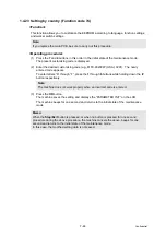
1.4.30 Output of transmission log to the telephone line (Function code 87)
<Function>
This function outputs the transmission log (that the machine has stored about the latest
transmission) to the telephone line. It allows the service personnel to receive the transmission
log of the user's machine at a remote location and use it for analyzing problems arising in the
user's machine.
<Operating procedure>
(1) If the user's machine has a transmission-related problem, call the user's machine at a
remote location from your machine.
(2) If the line is connected, have the user perform the following:
1) Hook up to the external phone.
2) Press the
Menu
,
Start/Black
,
Menu
buttons in this order.
3) Press the
8
and
7
buttons.
The above operation makes the user's machine send CNG to your machine for sending
the transmission log.
(3) If you hear the CNG sent from the user's machine, press the
Start/Black
button of your
machine. Your machine will start to receive the transmission log from the user's machine.
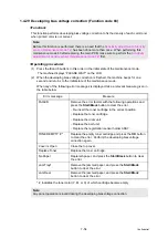
1.4.31 Counter reset after replacing the fuser unit and paper feeding kit
(Function code 88)
<Function>
The number of replacement is increased by one, and the warning indication “Replace ***” is
cleared, with implementing this operation after replacing the fuser unit and paper feed Kit.
<Operating procedure>
(1) Press the
8
button twice in the initial state of the maintenance mode.
(2) The LCD shows the “Reset Fuser Unit”.
(3) Press the
or
button to select the item you want to reset. The LCD shows.
“Reset-Fuser Unit”
“Reset PF-KIT T”
(4) Press the
OK
or
Start/Black
button, then “OK?” will appear on the LCD.
(5) Press the
OK
or
Start/Black
button to reset the counter of the selected part and returns
the operating procedure (2) mode.
(6) When the
Stop/Exit
button is pressed, the machine beeps for one second and returns to
the initial state of the maintenance mode.
1.4.32 Exit from maintenance mode (Function code 99)
<Function>
The machine returns to the ready state.
<Operating procedure>
(1) Press the
9
button twice in the initial state of the maintenance mode.
(2) The maintenance mode is finished, and the machine returns to the ready state.
Summary of Contents for DCP-9010CN
Page 11: ...Confidential CHAPTER 1 SPECIFICATIONS ...
Page 53: ...Confidential CHAPTER 2 THEORY OF OPERATION ...
Page 90: ...Confidential CHAPTER 3 ERROR INDICATION AND TROUBLESHOOTING ...
Page 201: ...Confidential CHAPTER 4 PERIODICAL MAINTENANCE ...
Page 224: ...Confidential CHAPTER 5 DISASSEMBLY AND ASSEMBLY ...
Page 440: ...Confidential CHAPTER 6 ADJUSTMENTS AND UPDATING OF SETTINGS REQUIRED AFTER PARTS REPLACEMENT ...
Page 446: ...6 5 Confidential 10 Alert warning message appears click Continue Anyway to proceed ...
Page 456: ...Confidential CHAPTER 7 SERVICE FUNCTIONS ...
Page 464: ...7 6 Confidential For color scanning Fig 7 2 ...
Page 487: ...7 29 Confidential Cover page sample Fig 7 13 End page sample Fig 7 14 ...
Page 492: ...7 34 Confidential Color registration adjustment chart Fig 7 16 ...
Page 496: ...7 38 Confidential LED test pattern M68_L Fig 7 18 ...
Page 498: ...7 40 Confidential Fig 7 19 ...
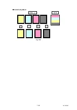
Page 500: ...7 42 Confidential Color test pattern Fig 7 20 MCYK Y C K M YCMK_ _A ...
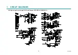
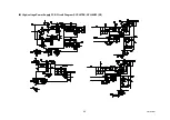
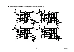
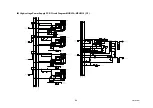
Page 518: ...Confidential CHAPTER 8 CIRCUIT DIAGRAMS WIRING DIAGRAM ...
Page 521: ...Confidential 8 2 High voltage Power Supply PCB Circuit Diagram SYS HITEK SPH 8N35 2 3 ...
Page 522: ...Confidential 8 3 High voltage Power Supply PCB Circuit Diagram SYS HITEK SPH 8N35 3 3 ...
Page 523: ...Confidential 8 4 High voltage Power Supply PCB Circuit Diagram MURATA MPH3316 1 3 ...
Page 524: ...Confidential 8 5 High voltage Power Supply PCB Circuit Diagram MURATA MPH3316 2 3 ...
Page 525: ...Confidential 8 6 High voltage Power Supply PCB Circuit Diagram MURATA MPH3316 3 3 ...
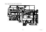
Page 526: ...Confidential 8 7 Low voltage Power Supply PCB Circuit Diagram 100V ...
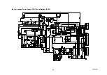
Page 527: ...Confidential 8 8 Low voltage Power Supply PCB Circuit Diagram 200V ...
Page 528: ...Confidential 8 9 NCU PCB Circuit Diagram USA Canada ...
Page 529: ...Confidential 8 10 NCU PCB Circuit Diagram Europe Asia Oceania China ...
Page 530: ...Confidential 8 11 NCU PCB Circuit Diagram South Africa Gulf ...
Page 531: ...Confidential 8 12 2 WIRING DIAGRAM Wiring Diagram 1 2 ...
Page 532: ...Confidential 8 13 Wiring Diagram 2 2 ...
Page 590: ...Confidential APPENDIX 3 SERIAL NUMBERING SYSTEM ...
Page 592: ...App 3 2 Confidential Serial number of the LED ASSY Print position Fig App 3 4 Serial number ...
Page 593: ...Confidential APPENDIX 4 SCREW CATALOGUE ...
Page 595: ...Confidential APPENDIX 5 REFERENCES ...
Page 597: ...Confidential APPENDIX 6 GLOSSARY ...


