


5-188
Confidential
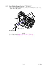
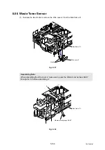
8.83 Registration Sensor Holder ASSY
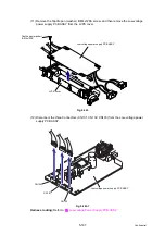
(1) Remove the Taptite cup S M3x6 SR screw from the Registration sensor holder ASSY.
Fig. 5-244
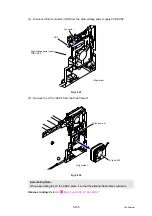
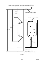
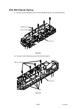
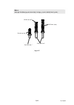
(2) Wire the harness and release the Hook. Slide the Registration sensor holder ASSY in the
direction of the arrow 2a, and remove it from the Registration sensor plate.
Fig. 5-245
Harness routing:
Refer to
Registration Sensor Holder ASSY.”
Assembling Note:
- Be careful not to place the harness between the Registration sensor holder ASSY and the
Registration sensor plate when assembling the Registration sensor holder ASSY to the
Registration sensor plate.
- A reinforcement plate for transportation is assembled to the Registration sensor holder
ASSY (service part). Remove the reinforcement plate for transportation from the
Registration sensor holder ASSY before assembling.
Registration sensor holder ASSY
Taptite cup S M3x6 SR
<Right side>
<Left side>
Hook
Registration sensor plate
Registration sensor holder ASSY
2b
2a
<A view>
A view
Registration sensor plate
<Right side>
<Left side>
2a
Summary of Contents for DCP-9010CN
Page 11: ...Confidential CHAPTER 1 SPECIFICATIONS ...
Page 53: ...Confidential CHAPTER 2 THEORY OF OPERATION ...
Page 90: ...Confidential CHAPTER 3 ERROR INDICATION AND TROUBLESHOOTING ...
Page 201: ...Confidential CHAPTER 4 PERIODICAL MAINTENANCE ...
Page 224: ...Confidential CHAPTER 5 DISASSEMBLY AND ASSEMBLY ...
Page 440: ...Confidential CHAPTER 6 ADJUSTMENTS AND UPDATING OF SETTINGS REQUIRED AFTER PARTS REPLACEMENT ...
Page 446: ...6 5 Confidential 10 Alert warning message appears click Continue Anyway to proceed ...
Page 456: ...Confidential CHAPTER 7 SERVICE FUNCTIONS ...
Page 464: ...7 6 Confidential For color scanning Fig 7 2 ...
Page 487: ...7 29 Confidential Cover page sample Fig 7 13 End page sample Fig 7 14 ...
Page 492: ...7 34 Confidential Color registration adjustment chart Fig 7 16 ...
Page 496: ...7 38 Confidential LED test pattern M68_L Fig 7 18 ...
Page 498: ...7 40 Confidential Fig 7 19 ...
Page 500: ...7 42 Confidential Color test pattern Fig 7 20 MCYK Y C K M YCMK_ _A ...
Page 518: ...Confidential CHAPTER 8 CIRCUIT DIAGRAMS WIRING DIAGRAM ...
Page 521: ...Confidential 8 2 High voltage Power Supply PCB Circuit Diagram SYS HITEK SPH 8N35 2 3 ...
Page 522: ...Confidential 8 3 High voltage Power Supply PCB Circuit Diagram SYS HITEK SPH 8N35 3 3 ...
Page 523: ...Confidential 8 4 High voltage Power Supply PCB Circuit Diagram MURATA MPH3316 1 3 ...
Page 524: ...Confidential 8 5 High voltage Power Supply PCB Circuit Diagram MURATA MPH3316 2 3 ...
Page 525: ...Confidential 8 6 High voltage Power Supply PCB Circuit Diagram MURATA MPH3316 3 3 ...
Page 526: ...Confidential 8 7 Low voltage Power Supply PCB Circuit Diagram 100V ...
Page 527: ...Confidential 8 8 Low voltage Power Supply PCB Circuit Diagram 200V ...
Page 528: ...Confidential 8 9 NCU PCB Circuit Diagram USA Canada ...
Page 529: ...Confidential 8 10 NCU PCB Circuit Diagram Europe Asia Oceania China ...
Page 530: ...Confidential 8 11 NCU PCB Circuit Diagram South Africa Gulf ...
Page 531: ...Confidential 8 12 2 WIRING DIAGRAM Wiring Diagram 1 2 ...
Page 532: ...Confidential 8 13 Wiring Diagram 2 2 ...
Page 590: ...Confidential APPENDIX 3 SERIAL NUMBERING SYSTEM ...
Page 592: ...App 3 2 Confidential Serial number of the LED ASSY Print position Fig App 3 4 Serial number ...
Page 593: ...Confidential APPENDIX 4 SCREW CATALOGUE ...
Page 595: ...Confidential APPENDIX 5 REFERENCES ...
Page 597: ...Confidential APPENDIX 6 GLOSSARY ...


