


APPENDIX 3 FIRMWARE SWITCHS (WSW)
A-48
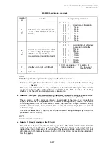
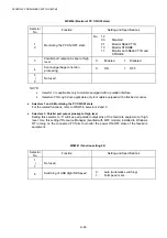
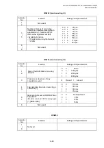
WSW46 (Monitor of PC ON/OFF state)
Selector
No.
Function
Setting and Specifications
1
2
Monitoring the PC ON/OFF state
No. 1 2
0
0
:
Disabled
0 1 : Monitor SELECT IN
1
0
:
Monitor
STROBE
1 1 :
Monitor both SELECT IN and
STROBE
3
Parallel port output pins kept at high
level
0: Enabled
1:
Disabled
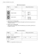
4
Scanned garbage correction
processing
0: ON
1:
OFF
5
|
8
Not used.
NOTE:
•
Selector 3 is applicable only to models equipped with a parallel interface.
•
Selectors 6 through 8 are applicable only to models equipped with a flat-bed scanner.
l
Selectors 1 and 2: Monitoring the PC ON/OFF state
For the related functions, refer to WSW36, selectors 2 and 3.
l
Selectors 3: Parallel port output pins kept at high level
Setting this selector to “0” will keep all parallel output pins of the facsimile equipment at high
level. Use this setting if Resource Manager (bundled with MFC models) installed to Windows
NT running on the connected PC fails to monitor the power ON/OFF state of the facsimile
equipment.
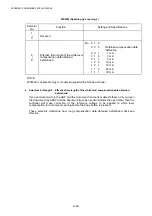
WSW47 (Function setting 22)
Selector
No.
Function
Setting and Specifications
1
|
7
Not used.
8
Switching of USB High/Full Speed
0:
Auto (Automatic switching)
1:
Full speed is set.
Summary of Contents for DCP-8040
Page 276: ...CHAPTER 7 MAINTENANCE MODE 7 6 Fig 7 3 l m a b c d e f g h i j k ...
Page 347: ...APPENDIX 4 CIRCUIT DIAGRAMS A 50 Appendix 4 1 Main PCB Circuit Diagram 1 7 ...
Page 349: ...APPENDIX 4 CIRCUIT DIAGRAMS A 52 Appendix 4 3 Main PCB Circuit Diagram 3 7 ...
Page 351: ...APPENDIX 4 CIRCUIT DIAGRAMS A 54 Appendix 4 5 Main PCB Circuit Diagram 5 7 ...
Page 353: ...APPENDIX 4 CIRCUIT DIAGRAMS A 56 Appendix 4 7 Main PCB Circuit Diagram 7 7 ...
Page 355: ...APPENDIX 4 CIRCUIT DIAGRAMS A 58 Appendix 4 9 Engine PCB Circuit Diagram 1 2 ...
Page 357: ...APPENDIX 4 CIRCUIT DIAGRAMS A 60 Appendix 4 11 NCU PCB Circuit Diagram U S A ...
Page 359: ...APPENDIX 4 CIRCUIT DIAGRAMS A 62 Appendix 4 13 NCU PCB Circuit Diagram Asia ...
Page 361: ...APPENDIX 4 CIRCUIT DIAGRAMS A 64 Appendix 4 15 Control Panel PCB Circuit Diagram ...
Page 367: ...April 04 SM FAX027 5 8C5903 Printed in Japan ...