


APPENDIX 3 FIRMWARE SWITCHS (WSW)
A-34
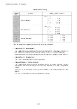
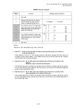
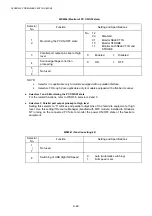
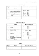
WSW29 (Function setting 7)
Selector
No.
Function
Setting and Specifications
1
|
8
Not used.
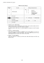
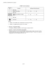
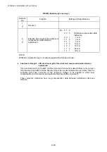
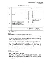
WSW30 (Function setting 8)
Selector
No.
Function
Setting and Specifications
1
|
3
Not used.
4
Duty cycle control of pulsed current
for the heat-fixing unit
0: OFF
1: ON
5
Not used.
6
|
8
Not used.
NOTE:
Selector 4 is applicable to the European version only.
z
Selector 4: Duty cycle control of pulsed current for the heat-fixing unit
Setting this selector to "1" activates the duty cycle control that suppresses the rush current.
The duty cycle is 10-ms ON and 20-ms OFF.
However, the duty cycle control may emit switching noise to the AC line. Depending upon
the codes and regulations in the country, this selector should be set to "0."
Summary of Contents for DCP-8040
Page 276: ...CHAPTER 7 MAINTENANCE MODE 7 6 Fig 7 3 l m a b c d e f g h i j k ...
Page 347: ...APPENDIX 4 CIRCUIT DIAGRAMS A 50 Appendix 4 1 Main PCB Circuit Diagram 1 7 ...
Page 349: ...APPENDIX 4 CIRCUIT DIAGRAMS A 52 Appendix 4 3 Main PCB Circuit Diagram 3 7 ...
Page 351: ...APPENDIX 4 CIRCUIT DIAGRAMS A 54 Appendix 4 5 Main PCB Circuit Diagram 5 7 ...
Page 353: ...APPENDIX 4 CIRCUIT DIAGRAMS A 56 Appendix 4 7 Main PCB Circuit Diagram 7 7 ...
Page 355: ...APPENDIX 4 CIRCUIT DIAGRAMS A 58 Appendix 4 9 Engine PCB Circuit Diagram 1 2 ...
Page 357: ...APPENDIX 4 CIRCUIT DIAGRAMS A 60 Appendix 4 11 NCU PCB Circuit Diagram U S A ...
Page 359: ...APPENDIX 4 CIRCUIT DIAGRAMS A 62 Appendix 4 13 NCU PCB Circuit Diagram Asia ...
Page 361: ...APPENDIX 4 CIRCUIT DIAGRAMS A 64 Appendix 4 15 Control Panel PCB Circuit Diagram ...
Page 367: ...April 04 SM FAX027 5 8C5903 Printed in Japan ...