


APPENDIX 3 FIRMWARE SWITCHS (WSW)
A-24
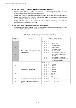
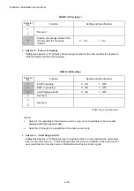
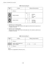
WSW17 (Function setting 2)
Selector
No.
Function
Setting and Specifications
1
2
Off-hook alarm
No. 1
2
0
0
:
No
alarm
0
1
:
Always
valid
1
X
:
Valid except when
'call reservation'
is selected.
3
4
Not used.
5
Calendar clock type
0:
U.S.A. type
1: European type
6 Not
used.
7 Non-ring
reception
0:
OFF
1:
ON
8 Not
used.
l
Selectors 1 and 2: Off-hook alarm
These selectors activate or deactivate the alarm function which sounds an alarm when the
handset is off the hook after the communication is completed.
The off-hook alarm works also for an external telephone connected to the EXT modular
socket.
l
Selector 5: Calendar clock type
If this selector is set to "0" (USA), the MM/DD/YY hh:mm format applies; if it is set to "1"
(Europe), the DD/MM/YY hh:mm format applies: DD is the day, MM is the month, YY is the
last two digits of the year, hh is the hour, and mm is the minute.
l
Selector 7: Non-ring reception
Setting this selector to "1" makes the machine receive calls without ringer sound if the ring
delay is set to 0.
Summary of Contents for DCP-8040
Page 276: ...CHAPTER 7 MAINTENANCE MODE 7 6 Fig 7 3 l m a b c d e f g h i j k ...
Page 347: ...APPENDIX 4 CIRCUIT DIAGRAMS A 50 Appendix 4 1 Main PCB Circuit Diagram 1 7 ...
Page 349: ...APPENDIX 4 CIRCUIT DIAGRAMS A 52 Appendix 4 3 Main PCB Circuit Diagram 3 7 ...
Page 351: ...APPENDIX 4 CIRCUIT DIAGRAMS A 54 Appendix 4 5 Main PCB Circuit Diagram 5 7 ...
Page 353: ...APPENDIX 4 CIRCUIT DIAGRAMS A 56 Appendix 4 7 Main PCB Circuit Diagram 7 7 ...
Page 355: ...APPENDIX 4 CIRCUIT DIAGRAMS A 58 Appendix 4 9 Engine PCB Circuit Diagram 1 2 ...
Page 357: ...APPENDIX 4 CIRCUIT DIAGRAMS A 60 Appendix 4 11 NCU PCB Circuit Diagram U S A ...
Page 359: ...APPENDIX 4 CIRCUIT DIAGRAMS A 62 Appendix 4 13 NCU PCB Circuit Diagram Asia ...
Page 361: ...APPENDIX 4 CIRCUIT DIAGRAMS A 64 Appendix 4 15 Control Panel PCB Circuit Diagram ...
Page 367: ...April 04 SM FAX027 5 8C5903 Printed in Japan ...