


MFC-8440/8840D/8840DN, DCP-8040/8045D/8045DN
SERVICE MANUAL
A-21
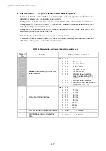
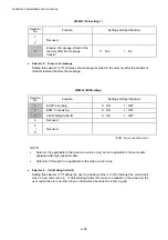
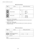
WSW14 (AUTO ANS facility setting)
Selector
No.
Function
Setting and Specifications
1
2
Frequency band selection
(Lower limit)
No. 1 2
0 0 : 13
Hz
0 1 : 15
Hz
1 0 : 23
Hz
1 1 : 20
Hz
3
4
Frequency band selection
(Upper limit)
No. 3 4
0 0 : 30
Hz
0 1 : 55
Hz
1 0 : 70
Hz
1 1 : 200
Hz
5
|
8
No. of rings in AUTO ANS mode
No. 5 6 7 8
0 0 0 0 : Fixed
to
once
0 0 0 1 : Fixed
to
2
times
0 0 1 0 : Fixed
to
3
times
0 0 1 1 : Fixed
to
4
times
0 1 0 0 : 1
to
2
times
0 1 0 1 : 1
to
3
times
0 1 1 0 : 1
to
4
times
0 1 1 1 : 1
to
5
times
1 0 0 0 : 2
to
3
times
1 0 0 1 : 2
to
4
times
1 0 1 0 : 2
to
5
times
1 0 1 1 : 2
to
6
times
1 1 0 0 : 1
to
10
times
1 1 0 1 : 2
to
10
times
1 1 1 0 : 3
to
5
times
1 1 1 1 : 4
to
10
times
l
Selectors 1 through 4: Frequency band selection
These selectors are used to select the frequency band of calling signals for activating the
AUTO ANS facility.
In the French versions, if the user sets the PBX to OFF from the control panel, the setting
made by selectors 1 and 2 will take no effect and the frequency's lower limit will be fixed to 32
Hz. (Even if the setting made by these selectors does not apply, it will be printed on the
configuration list.)
l
Selectors 5 through 8: No. of rings in AUTO ANS mode
These selectors set the number of rings to initiate the AUTO ANS facility.
Summary of Contents for DCP-8040
Page 276: ...CHAPTER 7 MAINTENANCE MODE 7 6 Fig 7 3 l m a b c d e f g h i j k ...
Page 347: ...APPENDIX 4 CIRCUIT DIAGRAMS A 50 Appendix 4 1 Main PCB Circuit Diagram 1 7 ...
Page 349: ...APPENDIX 4 CIRCUIT DIAGRAMS A 52 Appendix 4 3 Main PCB Circuit Diagram 3 7 ...
Page 351: ...APPENDIX 4 CIRCUIT DIAGRAMS A 54 Appendix 4 5 Main PCB Circuit Diagram 5 7 ...
Page 353: ...APPENDIX 4 CIRCUIT DIAGRAMS A 56 Appendix 4 7 Main PCB Circuit Diagram 7 7 ...
Page 355: ...APPENDIX 4 CIRCUIT DIAGRAMS A 58 Appendix 4 9 Engine PCB Circuit Diagram 1 2 ...
Page 357: ...APPENDIX 4 CIRCUIT DIAGRAMS A 60 Appendix 4 11 NCU PCB Circuit Diagram U S A ...
Page 359: ...APPENDIX 4 CIRCUIT DIAGRAMS A 62 Appendix 4 13 NCU PCB Circuit Diagram Asia ...
Page 361: ...APPENDIX 4 CIRCUIT DIAGRAMS A 64 Appendix 4 15 Control Panel PCB Circuit Diagram ...
Page 367: ...April 04 SM FAX027 5 8C5903 Printed in Japan ...