


MFC-8440/8840D/8840DN, DCP-8040/8045D/8045DN
SERVICE MANUAL
A-15
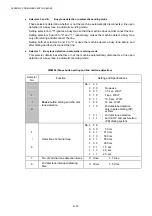
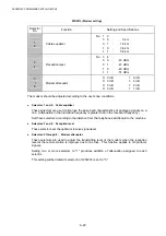
WSW08 (Dial tone setting 2)
Selector
No.
Function
Setting and Specifications
1
|
3
1st dial tone detection time
length
No. 1 2 3
0 0 0 :
50
ms
0 0 1 :
210
ms
0 1 0 :
500
ms
0 1 1 :
800
ms
1 0 0 :
900
ms
1 0 1 :
1.5
sec.
1 1 0 :
2.0
sec.
1 1 1 :
2.5
sec.
4
5
Time-out length for 1st and 2nd
dial tone detection
No. 4 5
0 0 : 10 sec.
0 1 : 20 sec.
1 0 : 15 sec.
1 1 : 30 sec.
6
|
8
Detection level of 1st dial tone
and busy tone before dialing
No. 6 7 8
0 0 0 :
-21
dBm
0 0 1 :
-24
dBm
0 1 0 :
-27
dBm
0 1 1 :
-30
dBm
1 0 0 :
-33
dBm
1 0 1 :
-36
dBm
1 1 0 :
-39
dBm
1 1 1 :
-42
dBm
NOTE:
The WSW08 is not applicable in those countries where no dial tone detection is supported,
e.g., U.S.A.
l
Selectors 1 through 3: 1st dial tone detection time length
Upon detection of the 1st dial tone for the time length set by these selectors, the machine
starts dialing.
This setting is effective only when selectors 1 through 3 of WSW05 are set to "1,1,1."
l
Selectors 4 and 5: Time-out length for 1st and 2nd dial tone detection
These selectors set the time-out length for the 1st and 2nd dial tone detection so that the
machine waits dial tone input for the specified time length and disconnects itself from the line
when no dial tone is inputted.
Summary of Contents for DCP-8040
Page 276: ...CHAPTER 7 MAINTENANCE MODE 7 6 Fig 7 3 l m a b c d e f g h i j k ...
Page 347: ...APPENDIX 4 CIRCUIT DIAGRAMS A 50 Appendix 4 1 Main PCB Circuit Diagram 1 7 ...
Page 349: ...APPENDIX 4 CIRCUIT DIAGRAMS A 52 Appendix 4 3 Main PCB Circuit Diagram 3 7 ...
Page 351: ...APPENDIX 4 CIRCUIT DIAGRAMS A 54 Appendix 4 5 Main PCB Circuit Diagram 5 7 ...
Page 353: ...APPENDIX 4 CIRCUIT DIAGRAMS A 56 Appendix 4 7 Main PCB Circuit Diagram 7 7 ...
Page 355: ...APPENDIX 4 CIRCUIT DIAGRAMS A 58 Appendix 4 9 Engine PCB Circuit Diagram 1 2 ...
Page 357: ...APPENDIX 4 CIRCUIT DIAGRAMS A 60 Appendix 4 11 NCU PCB Circuit Diagram U S A ...
Page 359: ...APPENDIX 4 CIRCUIT DIAGRAMS A 62 Appendix 4 13 NCU PCB Circuit Diagram Asia ...
Page 361: ...APPENDIX 4 CIRCUIT DIAGRAMS A 64 Appendix 4 15 Control Panel PCB Circuit Diagram ...
Page 367: ...April 04 SM FAX027 5 8C5903 Printed in Japan ...