App. 1-61
Confidential
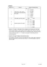
<WSW57>
Note:
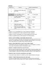
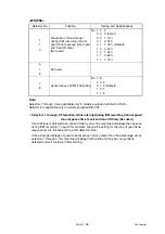
Selectors 1 through 6 are applicable only to models designed for the European market.
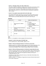
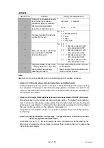
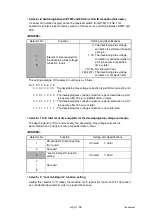
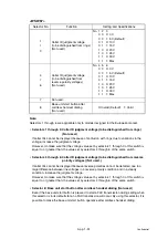
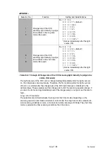
• Selectors 1 through 3: Caller ID judgment voltage (to be distinguished from rings)
(Not used.)
If caller IDs cannot be displayed because of confusion with rings due to variations in the
voltage, increase the judgment voltage.
However, do make sure that the voltage value set by selectors 1 through 3 of this switch is
equal to, or greater than, the value set by selectors 4 through 6 of the same switch.
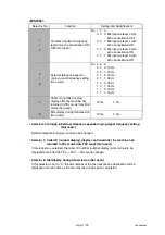
• Selectors 4 through 6: Caller ID judgment voltage (to be distinguished from reverse
polarity voltages) (Not used.)
If caller IDs cannot be displayed because reverse polarities cannot be detected due to a
large difference between line voltages in a reverse polarity condition and in a steady
condition, increase the judgment voltage.
However, do make sure that the voltage value set by selectors 1 through 3 of this switch is
equal to, or greater than, the value set by selectors 4 through 6 of the same switch.
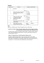
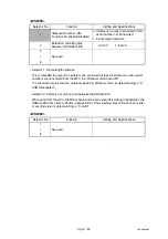
• Selector 8: Base unit start button after cordless handset dialing (Not used.)
Even if the base unit start button is pressed to start a FAX transmission during calling when
this selector is in its default state, no FAX transmission will occur. By using this selector, it is
possible to make the base unit start button operative after cordless handset dialing.
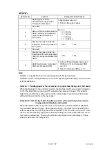
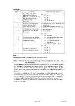
Selector No.
Function
Setting and Specifications
1
I
3
Caller ID judgment voltage
(to be distinguished from rings)
(Not used.)
No. 1 2 3
0 0 0: 0 V
0 0 1: 5 V (Default)
0 1 0: 10 V
0 1 1: 15 V
1 0 0: 20 V
1 0 1: 25 V
1 1 0: 30 V
1 1 1: Max.
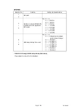
4
I
6
Caller ID judgment voltage
(to be distinguished from
reverse polarity voltages)
(Not used.)
No. 4 5 6
0 0 0: 0 V
0 0 1: 5 V (Default)
0 1 0: 10 V
0 1 1: 15 V
1 0 0: 20 V
1 0 1: 25 V
1 1 0: 30 V
1 1 1: Max.
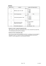
7
Not used.
8
Base unit start button after
cordless handset dialing
(Not used.)
0: Invalid (Default)
1: Valid
Summary of Contents for DCP-7030
Page 201: ...5 5 Confidential Print sample Fig 5 1 ...
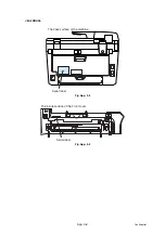
Page 226: ...5 30 Confidential Location of fans Fig 5 13 Fan motor 60 unit Right side ...
Page 234: ...6 2 Confidential LVPS PCB Circuit Diagram 100V ...
Page 235: ...6 3 Confidential LVPS PCB Circuit Diagram 200V ...
Page 239: ...6 7 Confidential Wiring Diagram ...

