


3-70
Confidential
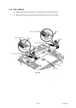
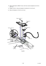
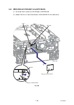
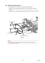
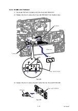
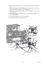
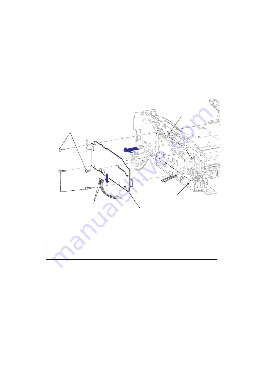
8.25 HIGH-VOLTAGE PS PCB ASSY
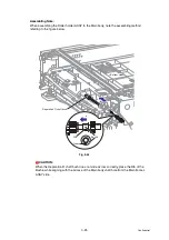
(1) Disconnect the two Connectors from the High-voltage PS PCB ASSY.
(2) Remove the two Taptite cup S M3x6 SR screws and the two Taptite bind B M4x12
screws.
(3) Release the Hook to remove the High-voltage PS PCB ASSY from the Drive sub ASSY.
Fig. 3-70
Note:
There are procedures for disassembling Main frame L ASSY after this procedure.
(
High-voltage PS PCB ASSY
Drive sub ASSY
Hook
Taptite bind B M4x12
Taptite cup S M3x6 SR
Connector
3
1
<Left side>
Summary of Contents for DCP-7030
Page 201: ...5 5 Confidential Print sample Fig 5 1 ...
Page 226: ...5 30 Confidential Location of fans Fig 5 13 Fan motor 60 unit Right side ...
Page 234: ...6 2 Confidential LVPS PCB Circuit Diagram 100V ...
Page 235: ...6 3 Confidential LVPS PCB Circuit Diagram 200V ...
Page 239: ...6 7 Confidential Wiring Diagram ...