4 - 21
Adjustment (Modules)
In
s
pect
ion and
Ad
ju
s
tme
n
t
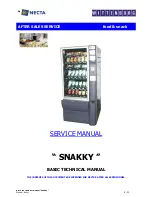
Inner rotary hook bracket position adjustment
1. Set the inner rotary hook in the outer rotary hook.
2. Loosen screw (bind 3X8).
3. Adjust the inner rotary hook bracket assy. attachment position so that contact between the inner rotary bracket
assy. and inner rotary hook is 1.6 – 1.8 mm, and fully tighten screw (bind 3X8).
Giza tite 5X16
torque:
1.18 - 1.57 N-m
Screw, bind 3
×
8
1.6 - 1.8mm
www.promelectroavtomat.ru
Summary of Contents for CS8000 Series
Page 1: ...www promelectroavtomat ru ...
Page 2: ...www promelectroavtomat ru ...
Page 10: ...viii www promelectroavtomat ru ...
Page 22: ...2 2 Main partslocation diagram Main unit www promelectroavtomat ru ...
Page 38: ...2 18 Upper shaft mechanismlocation diagram Main unit www promelectroavtomat ru ...
Page 45: ...2 25 Disassembly Thread tension mechanismlocation diagram Main unit www promelectroavtomat ru ...
Page 53: ...2 33 Disassembly Thread hook mechanism location diagram Main unit www promelectroavtomat ru ...
Page 56: ...2 36 Needle presser module breakout diagram Modules www promelectroavtomat ru ...
Page 65: ...2 45 Disassembly Feed module breakout diagram Modules www promelectroavtomat ru ...
Page 74: ...3 2 Thread tension mechanism location diagram Main unit www promelectroavtomat ru ...
Page 85: ...3 13 Assembly Thread hook mechanism location diagram Main unit www promelectroavtomat ru ...
Page 88: ...3 16 Upper shaft mechanism location diagram Main unit www promelectroavtomat ru ...
Page 115: ...3 43 Assembly Main parts location diagram Main unit www promelectroavtomat ru ...
Page 120: ...3 48 Needle presser modulebreakout diagram Modules www promelectroavtomat ru ...
Page 136: ...3 64 Feed module breakout diagram Modules www promelectroavtomat ru ...
Page 201: ...6 1 6Repair Manual www promelectroavtomat ru ...
Page 207: ...www promelectroavtomat ru ...
Page 208: ...www promelectroavtomat ru ...