4 - 16
Adjustment (Main Unit)
Clearance between the needle and the rotary hook point adjustmen
1. Attach the operation PCB assy. flat cable and power PCB assy. lead wire connector to the main PCB assy., and
attach the front cover to the arm bed.
2. Press
and
while turning the power on (the buzzer will sound four times, and test mode will start).
3. <S2>
Select
using
, press
three times, and set the needle bar to the right base line position.
<S3>
Select
using
or
, and after pressing
, press
three times, and set the needle bar to
the right base line position.
4. Turn off the power.
5. Remove screws M4 (two), and remove needle plate A (1).
6. Loosen screw, pan M3X12 (or remove it)
7. Hand turn the pulley until the right edge of the needle and the outer rotary hook tip meet.
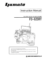
8. Adjust the gap between the needle and the outer rotary hook tip (front and back) to 0.1 mm or less using the
tightening depth of the adjusting screw.
9. Install and fully tighten screw, pan M3X12.
10. Attach needle plate A using screws M4 (two).
Screw, pan M3X12,
torque
0.78 – 1.18 N-m
0.1mm or less
Needle
Rear surface
Tip
Front surface
www.promelectroavtomat.ru
Summary of Contents for CS8000 Series
Page 1: ...www promelectroavtomat ru ...
Page 2: ...www promelectroavtomat ru ...
Page 10: ...viii www promelectroavtomat ru ...
Page 22: ...2 2 Main partslocation diagram Main unit www promelectroavtomat ru ...
Page 38: ...2 18 Upper shaft mechanismlocation diagram Main unit www promelectroavtomat ru ...
Page 45: ...2 25 Disassembly Thread tension mechanismlocation diagram Main unit www promelectroavtomat ru ...
Page 53: ...2 33 Disassembly Thread hook mechanism location diagram Main unit www promelectroavtomat ru ...
Page 56: ...2 36 Needle presser module breakout diagram Modules www promelectroavtomat ru ...
Page 65: ...2 45 Disassembly Feed module breakout diagram Modules www promelectroavtomat ru ...
Page 74: ...3 2 Thread tension mechanism location diagram Main unit www promelectroavtomat ru ...
Page 85: ...3 13 Assembly Thread hook mechanism location diagram Main unit www promelectroavtomat ru ...
Page 88: ...3 16 Upper shaft mechanism location diagram Main unit www promelectroavtomat ru ...
Page 115: ...3 43 Assembly Main parts location diagram Main unit www promelectroavtomat ru ...
Page 120: ...3 48 Needle presser modulebreakout diagram Modules www promelectroavtomat ru ...
Page 136: ...3 64 Feed module breakout diagram Modules www promelectroavtomat ru ...
Page 201: ...6 1 6Repair Manual www promelectroavtomat ru ...
Page 207: ...www promelectroavtomat ru ...
Page 208: ...www promelectroavtomat ru ...