background image

114

13. WARRANTY

This warranty certificate issued by Bronpi Calefacción S.L. extends to the repair and replacement of the equipment or any defective part 

under the following conditions:

13.1. 

WARRANTY VALIDITY

The warranty will only be valid if:

• 

The equipment has been installed by a qualified, accredited installer with   according to the norms and requirements of this manual 

and current regulations in each local region or country.

• 

The equipment must be tested for a sufficient time before additional operations of coating, painting, connections, etc. The warranty will 

not respond to the charges derived from uninstalling or installing again as well as the value of objects located in the installation room.  

• 

The warranty certificate must be completed and signed, it must be validated by the Qualified Technical Installer (QTI) and it must 

include the authorized sellers name and the name of the purchaser. 

• 

The defect appears within a period of time not more than 24 months since purchase invoice of the client. The date will be confirmed by 

the invoice and it should be completed properly, including the authorized seller name, the name of the purchaser, the description of 

the model and the purchase price.  This document must be preserved in good conditions and the Technical Installer may require it.

• 

After this time or if the following conditions have not been accomplished, the warranty shall terminate.

• 

The fault is recognised by the Technical Installer. The customer will not pay costs involved of the performance that will make the TAS, 

covered by the warranty.

        THE WARRANTY COMPLIES WITH THE EUROPEAN DIRECTIVE Nº 1999/44.

13.2. 

WARRANTY WILL NOT BE VALID IF

• 

The claim does not comply with the previous conditions.

• 

Expiration 24 months since the date of purchase of the product.

• 

Lack of fiscal documentation, alteration or ineligibility of the invoice as well as the lack of warranty number of the model.

• 

Mistakes in the installation or an installation that does not comply with the current norms and requirements included in this manual.

• 

Servicing records do not comply with the servicing requirements of the product such as described in the manual.  

• 

Improper modifications or damage to the equipment due to the change of non-original components or actions performed by staff not 

authorized by Bronpi Calefacción S.L.

• 

Presence of electrical and/or hydraulic installations which do not comply with the regulations.

• 

Damage caused by normal corrosion or deposition phenomena typical of heating systems. Likewise for water boilers.

• 

Damage caused by the improper use of the product, modifications or improper handling and, in particular, incorrect fuel loads over the 

one specified or unauthorized use of fuels, as prescribed in this manual.

• 

Damage resulting from atmospheric, chemical and electrochemical agents as well as the inefficiency or lack of flue pipe and other 

causes not deriving from the manufacture of the equipment.

• 

All transport damages (it is recommended to check carefully the product when you receive it) should be reported immediately to the 

distributor and will be reflected in the transport document and on the copy of the carrier.

13.3. 

EXCLUDED FROM THE WARRANTY

• 

Construction works. The warranty will not respond to the charges derived from uninstalling or installing again as well as the value of 

objects located in the installation room. 

• 

The joints, sheet or cast-iron grates or any other cast-iron piece that have suffered a deformation and/or break derived from an 

improper use or fuel or an overload of fuel. 

• 

Chrome or gold coloured parts and majolica and/or stone trims. Chromatic variations and differences in the quartering, graining or 

spots of the pieces do not change the quality of the product and this is not a reason for complaint because these are natural features 

of these materials. Likewise, the variations from the pictures that appear in the catalogue.

• 

For products that use water, pieces of the hydraulic circuit unconnected with the product.

• 

For products that use water, the heat exchanger is excluded from the warranty if an anti-condensation circuit is not installed.

• 

For products that use water, blow down operations are necessary to remove the air from the system.

• 

Interventions derived from water supply installations, electricity and external components where customers can intervene directly 

during the use are also excluded from the warranty.

• 

Maintenance and servicing tasks of the fireplace and the installation.

• 

If the model does not have any operation fault, attributable to Bronpi Calefacción S.L., the cost of the intervention must be charged to 

the consumer.

13.4. 

EXCLUSION OF LIABILITY

Bronpi Calefacción S.L. under no circumstances will accept any compensation for direct or indirect damages caused by the product or 

derived from it.

13.5. 

INDICATIONS IN CASE OF ABNORMAL FUNCTIONING OF THE MODEL

In case of malfunction of the equipment, the consumer will follow the next indications:

• 

Check the troubleshooting guide of this manual.

• 

Check if the problem is covered by the warranty.

• 

Contact your distributor where you bought the model and carry the purchase invoice and the information about where the product is 

installed. 

In the event that the model is covered under warranty, as provided by the DL n24 of 02/02/2002, you should contact the distributor where you 

bought the product. The distributor will contact Bronpi Calefacción S.L. and they will provide the distributor with the information about the 

solution.

W

ARR

ANTY

Summary of Contents for Dama Hydro

Page 1: ...IE HYDRO INSTALLATION OPERATING AND SERVICING INSTRUCTIONS HYDRO SERIES INSTRUCTIONS D INSTALLATION D UTILISATION ET D ENTRETIEN SÉRIE HYDRO INSTRUÇÕES DE INSTALAÇÃO USO E MANUTENÇÃO SÉRIE HYDRO ISTRUZIONI DI INSTALLAZIONE USO E MANUTENZIONE SERIE HYDRO ...

Page 2: ... INSTRUÇÕES DE INSTALAÇÃO USO E MANUTENÇÃO SÉRIE HYDRO 61 IT ISTRUZIONI DI INSTALLAZIONE USO E MANUTENZIONE SERIE HYDRO 81 FT FICHAS TÉCNICAS DESPIECES TECHNICAL SPECIFICATIONS EXPLODED DRAWINGS FICHES TECHNIQUES DÉTAIL DES PIÈCES FICHAS TÉCNICAS DESMONTAGEM SCHEDA TECNICA ESPLOSI 100 CONDICIONES DE GARANTÍA WARRANTY CONDITIONS CONDITIONS DE LA GARANTIE CONDIÇÕES DA GARANTIA CONDIZIONI DI GARANZIA...

Page 3: ...9 5 MODALIDAD USUARIO 17 9 5 1 ENCENDIDO DE LA ESTUFA 17 9 5 2 ESTUFA EN FUNCIONAMIENTO 17 9 5 3 CAMBIO DE LA TEMPERATURA AMBIENTE DE CONSIGNA 17 9 5 4 CAMBIO DE LA TEMPERATURA DE CONSIGNA DEL AGUA 18 9 5 5 LA TEMPERATURA AMBIENTE O DE AGUA ALCANZA LA TEMPERATURA FIJADA POR EL USUARIO 18 9 5 6 LIMPIEZA DEL QUEMADOR 18 9 5 7 APAGADO DE LA ESTUFA 18 9 5 8 ESTUFA APAGADA 18 9 5 9 REENCENDIDO DE LA ES...

Page 4: ...entra una caja bolsa con un guante térmico que nos permite manipular la maneta de la puerta y otros componentes quemador El cable eléctrico de interconexión entre la termoestufa y la red Un gancho accesorio manos frías para facilitar la retirada y limpieza del quemador El mando a distancia de la termoestufa incluye pila Una hoja de color amarillo con las advertencias y consideraciones más importan...

Page 5: ... en la garantía a menos que el centro de asistencia pueda demostrar la presencia de un componente defectuoso SENSOR DE FLUJO Tecnología Oasys Su termoestufa dispone de un sensor de flujo ver dibujo D5 situado en el tubo de aspiración de aire primario que detecta la correcta circulación del aire comburente y de la descarga de humos En caso de insuficiencia de entrada de aire consecuencia de una inc...

Page 6: ...rante la instalación de la estufa existen ciertos riegos que hay que tener en cuenta por lo que se deben adoptar las siguientes medidas de seguridad a Mantenga alejado cualquier material inflamable o sensible al calor muebles cortinas ropas a una distancia mínima de seguridad de unos 150cm b Cuando la termoestufa se instale sobre un suelo no completamente refractario será necesario colocar una bas...

Page 7: ...ad demasiado elevada Si en cambio el humo es gris o negro significa que la combustión no es completa es necesaria una mayor cantidad de aire secundario La conexión de la termoestufa se debe realizar con tubos rígidos de acero aluminado o acero inoxidable Está prohibido el uso de tubos flexibles metálicos o de fibrocemento porque perjudican la seguridad de la unión puesto que están sujetos a tirone...

Page 8: ... de unas aberturas que se comuniquen con el exterior debe poder circular aire para la combustión incluso con las puertas y ventanas cerradas La toma de aire debe estar posicionada de manera que no pueda obstruirse Además debe ser comunicante con el ambiente de instalación de la termoestufa y estar protegida por una rejilla La superficie mínima de esta toma de aire no debe ser inferior a 100 cm2 Cu...

Page 9: ...todas las tuberías de la instalación para eliminar los posibles residuos que podrían comprometer el buen funcionamiento de algún componente de la instalación bombas válvulas etc b Un control para comprobar el tiro adecuado de la salida de humos la ausencia de estrangulamientos y que en el conducto de salida de humos no exista descargas de otros equipos c Realice también el correcto purgado de la i...

Page 10: ...endida durante por lo menos 6 10 horas continuas 3 Repetir esta operación como mínimo 4 5 o más veces según su disponibilidad 4 Durante las primeras puestas en marcha ningún objeto se debería apoyar sobre el aparato y en particular sobre las superficies lacadas Las superficies lacadas no se deben tocar durante el calentamiento 8 MANTENIMIENTO Y CUIDADO Las operaciones de mantenimiento garantizan q...

Page 11: ...necesario limpiar la cámara de los intercambiadores de calor pues el hollín que se acumula en la parte superior dificulta la circulación correcta de los humos Para acceder a esta zona deberá retirar el techo de la termoestufa y posteriormente realizar las siguientes operaciones Extraer los pomos de los rascadores para que la tapa se pueda extraer ver dibujo D19 Extraer la tapa de registro aflojand...

Page 12: ...lojamiento de las cenizas cuando sea necesario Aspirar el fondo del depósito del pellet siempre que sea necesario Limpiar el interior de la cámara de combustión aspirando las paredes con un aspirador adecuado Limpieza del motor de extracción de humos cámara de combustión completa depósito de pellet sustitución completa de las juntas y nuevo siliconado donde sea necesario conducto de humos registro...

Page 13: ...STANCIA Junto con su termoestufa podrá encontrar un mando a distancia por infrarrojos a través del cual podrá controlar su termoestufa a distancia ver dibujo D28 Las funciones de las teclas son las siguientes Tecla Descripción Modalidad Descripción del funcionamiento 1 Incrementa temperatura PROGRAMACIÓN Modifica incrementa el valor del menú seleccionado ON OFF Incrementa el valor de la temperatur...

Page 14: ...or los diferentes submenús e introducir los datos modificando los valores con las teclas 1 y 2 La tarjeta está equipada con batería de litio que le permite la autonomía del reloj interno de 3 5 años ver dibujo D29 9 4 3 MENÚ 2 AJUSTE PROGRAMA PROGRAMACIÓN HORARIA DE LA TERMOESTUFA NOTA IMPORTANTE Antes de proceder a la configuración de la programación de su termoestufa compruebe que la fecha y hor...

Page 15: ...rmoestufa es necesario acceder al submenú 2 1 habilita crono y pulsando la tecla nº 3 aparecerá por defecto la siguiente pantalla ver dibujo D31 Por defecto en el margen superior izquierdo nos sale la palabra off Tecleando la tecla nº 1 ó nº 2 debemos cambiarlo a on para informar a la termoestufa de nuestra intención de programarla ver dibujo D32 A continuación elegir la programación que queremos ...

Page 16: ...s según nuestras necesidades Para su activación hay que partir de la siguiente pantalla ver dibujo D39 Pulsando una sola vez la tecla nº 3 accedemos al submenú de programación semanal de la termoestufa Por defecto aparecerá la siguiente pantalla ver dibujo D40 Debemos de cambiar la opción off a on pulsando las teclas nº 1 ó nº 2 Con ello confirmamos a la máquina que la programación semanal ha sido...

Page 17: ...icamente Es decir si usted selecciona que la temperatura de ambiente de consigna sea por ejemplo 22ºC la termoestufa se apagará cuando la temperatura del ambiente sea de 24º y se volverá a encender de manera automática cuando la temperatura del ambiente baje a 20ºC independientemente de que no se haya alcanzado la temperatura de consigna del agua impuesta En caso de permanecer desactivada esta fun...

Page 18: ...do 9 5 2 ESTUFA EN FUNCIONAMIENTO Una vez alcanzada la temperatura de humos configurada la termoestufa se considera en funcionamiento pasando en primer lugar al estado Fuego Presente que durará escasos minutos antes de finalizar la fase de encendido Finalizada correctamente la fase de encendido de la termoestufa ésta entra en modo Trabajo que representa el modo normal de funcionamiento ver dibujo ...

Page 19: ...os segundos Una vez apagada la estufa comienza la fase de limpieza final en la que el alimentador de pellet se detiene y el extractor de humos y la circuladora seguirán funcionando Dicha fase de limpieza no finalizará hasta que la termoestufa no haya alcanzado la temperatura de enfriamiento adecuada ver dibujo D62 9 5 8 ESTUFA APAGADA En el dibujo D63 aparece la información del display cuando la t...

Page 20: ... de limpieza final 10 7 ALARMA TÉRMICA Si durante la fase de trabajo aparece la alarma de seguridad térmica ver dibujo D71 aparecerá en el display la imagen que se muestra e inmediatamente se activa el procedimiento de apagado Esta alarma indica un sobrecalentamiento en el interior del depósito del combustible y por lo tanto el dispositivo de seguridad bloquea el funcionamiento de la termoestufa E...

Page 21: ...ARMA ANOMALÍA EN SONDA DE AGUA Esta alarma ocurre cuando la sonda que detecta la temperatura del agua se desconecta o se avería Durante la alarma la termoestufa ejecuta el procedimiento de apagado ver dibujo D76 En caso de que esta alarma ocurra debe contactar con el servicio de asistencia técnica 10 13 ALARMA TEMPERATURA AGUA Se produce cuando la sonda detecta una temperatura de agua superior a 9...

Page 22: ...el termostato Comprobar la causa del exceso de temperatura que ha provocado el sobrecalentamiento caída de pellet exceso de tiro tipo de combustible funcionamiento de turbina tangencial AL 8 DEPRESIÓN La cámara de combustión está en depresión Verificar que la cámara es hermética comprobar cierres juntas de estanqueidad etc comprobar que la instalación de gases es adecuada exceso de tramos horizont...

Page 23: ... 36 9 4 8 MENU 7 STOVE STATE 36 9 5 USER MODE 37 9 5 1 IGNITION OF THE STOVE 37 9 5 2 STOVE IN OPERATION 37 9 5 3 CHANGE OF THE SET POINT ROOM TEMPERATURE 37 9 5 4 CHANGE WATER TEMPERATURE SET 37 9 5 5 ROOM OR WATER TEMPERATURE REACHES TEMPERATURE FIXED BY THE USER 38 9 5 6 BURNER CLEANING 38 9 5 7 TURNING OFF THE STOVE 38 9 5 8 STOVE TURNED OFF 38 9 5 9 RE IGNITION OF THE STOVE 38 10 ALARMS 38 10...

Page 24: ...e and the electrical network A hook cold hands handle to make easier the removing and cleaning of the burner The remote control of the thermo stove battery included A yellow leaflet with the most important warnings and considerations A book in order to register all maintenance tasks performed to the thermo stove as well as this installation use and servicing manual Inside the combustion chamber yo...

Page 25: ...humidity atmospheric pressure etc To that end the fitter must access the technical menu the geographical altitude of the equipment installation place HYDRAULIC PRESSURE TRANSDUCER If the pressure of the heating system is lower than 0 4 bars the boiler will cease feeding fuel and ultimately close down and stop If the pressure inside the heating system exceeds 2 5 bars the display will show the alar...

Page 26: ...the loading door b Put the fire out by using carbon dioxide extinguishers CO2 powder c Request for the immediate intervention of the fire fighters DO NOT PUT OUT THE FIRE WITH WATER UK HETAS regulations as stated in document J combustion appliances and fuel storage systems Whilst the document J gives the guidance for compliance the installer must interpret the guidance from manufactures for the co...

Page 27: ...ly to a bad draught It is necessary to comply with the following requirements for the proper operation of the thermo stove The interior section must be preferably circular It must be thermally insulated along its entire length in order to prevent condensation the smoke is liquefied by heat shock and even more if the installation is outside the house If we use metallic pipe for the installation out...

Page 28: ...allows the regular inspection or the heavy dust download There will not be more than 4 changes of direction including the register T for the cleaning In drawing D10 are represented the basic requirements for the chimney installation of a thermo stove The flue must be away from flammable or combustible materials through an appropriate insulation or an air chamber Inside the pipes it is forbidden th...

Page 29: ...TY VALVES The thermo stove is provided with a safety valve set at 3 bars pressure in order to work during possible increases of pressure on the installation The discharge flow rate of the safety valve must allow to discharge an amount of vapour not lower than Q 0 58 kg h where Q is the useful power transferred to the water of the generator expressed in kilowatts The fitter must control the maximum...

Page 30: ...tion follow the next verifications The electrical cable must be connected to the electrical network 230 Vac with a socket equipped with earthing system The bipolar switch placed on the rear side of the thermo stove must be in position I The pellet tank must be supplied The combustion chamber must be clean The burner must be clean and properly placed The combustion chamber door must be closed corre...

Page 31: ...RTANT Clean the glass only when it is cold in order to avoid possible explosion You can use specific products You can find Bronpi vitroceramic cleaning product at the same Bronpi distributor where you bought your stove see drawing D17 BREAKAGE OF GLASSES The glasses as they are vitro ceramic resist until 750ºC and they are not subject to thermal shocks The breakage can only be caused by mechanical...

Page 32: ...usively by an authorised technician This message is not an alarm but a reminder or warning Therefore it will allow you to use satisfactorily the thermo stove while this message is shown in the display see drawing D24 Please bear in mind that the thermo stove could need to be cleaned before the 1200 hours established by default or even after this This depends on the quality of the fuel used the smo...

Page 33: ...es back to the previous submenu value 6 Increases power ON OFF Increases the output value of the thermo stove MENU Moves to the following menu option PROGRAMMING Moves to the following submenu option 1 Pressing button nº 1 only one time we entry to the adjustment of the water temperature 2 Pressing button nº 2 only one time we entry to the adjustment of the room temperature 9 3 GENERAL INFORMATION...

Page 34: ...y 05 Month 06 Year 02 Programme setting See point 10 4 3 03 Select Language 01 Italian 02 French 03 English 04 German 05 Portuguese 06 Spanish 04 Stand by Mode ON OFF 05 Sound mode ON OFF 06 Initial load Set 07 Stove State Provides information on the status of the thermo stove 9 4 2 MENU 1 CLOCK The clock sets the time and date To set up the clock you have to move through the different submenus an...

Page 35: ...e can move to menu nº 2 Programme Adjustment see drawing D30 We need to confirm the access to this programme by pressing button nº3 SET To see different sub menus use buttons nº 5 and nº 6 Sub menu 02 01 Enable chrono To programme the thermo stove it is necessary to access sub menu 2 1 Enable chrono and pressing button nº 3 will show the next screen see drawing D31 The default in the top left marg...

Page 36: ...y set up of the thermo stove we need to take into account that in that case we have 4 different times to start and stop So we need to ascribe to every day of the week the activation or not as appropriate In order to activate them we need to start from the following screen see drawing D39 By pressing only once button no 3 we access the weekly programme sub menu of the thermo stove By default it wil...

Page 37: ... set temperature minus a differential 2ºC the thermo stove automatically restarts an ignition cycle It means that if you choose an ambient temperature of 22ºC the thermo stove will turn off when the room temperature is 24º C and it will restart automatically when the ambient temperature falls to 20ºC independently of the water temperature In case of the Stand by Mode is deactivated by default the ...

Page 38: ...ease it respectively See drawing D57 If we want the thermo stove to be controlled by an external thermostat you should contact the technical service authorised by Bronpi Calefacción S L because it is necessary to activate this external thermostat in the technical menu Connection of a volt free signal from a room thermostat or heating controller to the rear of the thermo stove and the correct softw...

Page 39: ...tion see drawing D64 10 ALARMS In case of an anomaly during operation the electronics of the thermo stove intervene and highlight the irregularities that have taken place in the standard operation of the thermo stove depending on the type of fault Every alarm situation puts the thermo stove to be an automatic lock out state By pressing button 4 we can unlock it Once the thermo stove has reached th...

Page 40: ...red when there is a pressure change in the combustion chamber door open dirty ash reservoirs down draughts blocked flue etc The electronic pressure switch locks the operation of the thermo stove and shows the alarm After that the turn off stage will be immediately activated see drawing D72 10 9 LACK OF PRIMARY AIR INTAKE FLOW ALARM Your thermo stove has a flow sensor placed inside the primary air ...

Page 41: ...electrical connection or replace it AL 5 START UP FAILURE The fuel does not fall or burn Check the geared motor and the resistor way of working Check a possible blockage of the auger feeder Verify that there is fuel in the tank AL 6 NO PELLET There is no fuel in the hopper or it does not fall inside the burner Refill tank Check the auger s operation Check the fuel characteristics and that it has n...

Page 42: ...CTION LANGAGE 55 9 4 5 MENU 4 MODE D ATTENTE 55 9 4 6 MENU 5 MODE SONORE 56 9 4 7 MENU 6 CHARGE INITIAL 56 9 4 8 MENU 7 ÉTAT DU THERMOPOÊLE 56 9 5 MODE UTILISATEUR 56 9 5 1 ALLUMAGE DU THERMOPOÊLE 56 9 5 2 POÊLE EN FONCTIONNEMENT 56 9 5 3 CHANGEMENT DE LA TEMPÉRATURE AMBIANTE DE CONSIGNE 57 9 5 4 CHANGEMENT DE LA TEMPÉRATURE DE CONSIGNE DE L EAU 57 9 5 5 LA TEMPÉRATURE AMBIANTE OU DE L EAU ATTEINT...

Page 43: ...le électrique d interconnexion entre le thermopoêle et le réseau Un crochet accessoire mains froides pour faciliter l enlèvement et nettoyage du brûleur La télécommande du thermopoêle piles inclues Une feuille jaune avec les avertissements et considérations plus importantes Un livre de maintenance qui contient un enregistrement des tâches réalisées au thermopoêle ainsi que le présent manuel d util...

Page 44: ...ogie Oasys Votre poêle est équipé d un capteur de débit voir dessin D5 placé sur le tuyau d aspiration d air primaire qui détecte la correcte circulation de l air comburant et du déchargement de fumées Dans le cas d une entrée d air insuffisante à conséquence d une sortie de fumées ou d une entrée d air incorrecte le capteur envoie un signal de verrouillage La TECHNOLOGIE OASYS Optimum Air System ...

Page 45: ...ibles ou susceptibles d être affectés par un choc thermique d Le poêle doit travailler uniquement avec le bac à cendres introduit et les portes fermées tant ce de la chambre de combustion comme ce du bac à cendres e On recommande d installer un détecteur de monoxyde de carbone CO dans la même pièce d installation de l appareil f Si vous avez besoin d un câble de plus longueur que celui fourni util...

Page 46: ...trôler si la fumée sortant de la cheminée est transparente Si la fumée est blanche signifie que l appareil n est pas réglé correctement ou le granulé de bois utilisé a une humidité trop haute Par contre si la fumée est grise ou noire signifie que la combustion n est pas complète il est nécessaire plus d air secondaire La connexion de l appareil doit se réaliser avec de tuyaux rigides en acier alum...

Page 47: ...poêle il est recommandé de s adresser à des professionnels spécialement formés Avant d installer et de mettre en fonction le poêle lire attentivement le contenu de ce manuel CONDUIT DE CHEMINEE ET CONDUIT DE RACCORDEMENT Le dimensionnement des conduits doit être validé par l installateur professionnellement qualifié selon le calcul à la norme EN 13384 1 et le DTU 24 1 CONDUIT DE RACCORDEMENT Dans ...

Page 48: ...ile PU Section libre minimale PU 25kW 50 cm PU 35kW 70 cm PU 50kW 100 cm PU 70kW 150 cm PU 100kW 200 cm Une partie de l air comburant peut être prélevée directement à l extérieur ou dans un vide sanitaire ventilé et raccordé directement à l appareil Avec cette solution il faut néanmoins conserver une ventilation du local Pour les implantations des prises d amenée d air frais il faut tenir compte d...

Page 49: ...avec la présence de quelques millimètres en faisant des chauffages nuisibles localisés Il est très recommandé de réaliser un traitement de l eau dans les cas suivants a La dureté de l eau maximale ne doit pas surpasser les 60 mg l Eau Légèrement Dure b Installations très étendues c Des remplissages successifs à cause de travails de maintenance de l installation ou produits par des pertes Pour le t...

Page 50: ...avez acheté votre poêle 8 2 USAGE DES GRATTOIRS Le nettoyage de la chambre de fumées permet de garantir que le rendement thermique soit constant pendant longtemps Ce type de maintenance doit être fait au moins une fois par jour Pour le réaliser il est suffit d utiliser les grattoirs correspondants qui se trouvent dans la partie supérieure du poêle en faisant un mouvement du bas vers le haut et vic...

Page 51: ...aire le couvercle du registre en dévissant les vis voir dessin D22 Nettoyer les cendres déposées dans le registre en décapant la suie déposée voir dessin D23 Nettoyer aussi les pales et la conque de l extracteur Retirer l extracteur s il est nécessaire voir dessin D23 Remettre les pièces Tester l herméticité du registre 8 9 ARRÊTS SAISONNIERS Si le thermopoêle ne vas pas être utilisé pendant longt...

Page 52: ...fonctionnement En particulier 1 La zone de l écran Valeur visualise la valeur que vous mettez 2 La zone de l écran Niveau de menu visualise le niveau de menu actuel Le dessin D27 montre le signifié des symboles qu il y a à gauche de l écran L éclairage de l écran dans la section état indique l activation du dispositif selon la liste suivante 9 2 FONCTIONS DES TOUCHES SUR LE DISPLAY Touche Descript...

Page 53: ...ance de sortie du thermopoêle MENU Passe à l option du menu précédent PROGRAMMATION Retour à l option de sous menu précédent 6 Augmente puissance ON OFF Augmente la valeur de la puissance de sortie du thermopoêle MENU Passe à l option de menu suivant PROGRAMMATION Passe à l option de sous menu suivant NOTE Il est possible d accéder au menu avec le télécommande mais il faut se rapprocher du display...

Page 54: ... 1 On Off 07 Jeudi Prog 1 On Off 08 Vendredi Prog 1 On Off 09 Samedi Prog 1 On Off 10 Dimanche Prog 1 On Off 11 Start Prog 2 Heure 12 Stop Prog 2 Heure 13 Lundi Prog 2 On Off 14 Mardi Prog 2 On Off 15 Mercredi Prog 2 On Off 16 Jeudi Prog 2 On Off 17 Vendredi Prog 2 On Off 18 Samedi Prog 2 On Off 19 Dimanche Prog 2 On Off 20 Start Prog 3 Heure 21 Stop Prog 3 Heure 22 Lundi Prog 3 On Off 23 Mardi Pr...

Page 55: ... voir dessin D36 On peut procéder de la même façon pour fixer la première heure d arrêt voir dessin D37 et D38 Si vous voulez programmer seulement une heure d initiation et d arrêt l option START 2 et STOP 2 doit montrer off Si vous voulez établir un deuxième horaire d allumage et éteint vous devez introduire les valeurs de la deuxième heure d initiation et d arrêt de la même façon qu on vient d e...

Page 56: ... journalier si on aurait besoin d une heure d initiation et d arrêt l option START 2 devrait indiquer OFF et l option STOP 2 également OFF Il est aussi possible programmer une heure d initiation automatique et éteint manuel ou à l inverse Exemple START 1 08 00 heures et STOP 1 off ou START 1 off et STOP 1 22 00 heures 9 4 4 MENU 3 SÉLECTION LANGAGE Il permet de sélectionner la langue de dialogue e...

Page 57: ...es fonctions disponibles Avant l allumage le display d un thermopoêle montre l écran du dessin D54 On peut voir l état éteint la température de l ambiante la puissance établie de travail et l heure actuelle 9 5 1 ALLUMAGE DU THERMOPOÊLE Pour allumer le poêle il faut appuyer la touche 4 pendant quelques seconds La présence d allumage apparaîtra dans le display comme il est montré sur le dessin D55 ...

Page 58: ... Voir dessin D60 Rappelez vous que si la modalité Mode d attente est activée une fois que l une des deux températures atteint la valeur fixée par l utilisateur plus une augmentation de 2ºC le thermopoêle s éteint automatiquement et se met en état d attente jusqu au moment où la température ambiante descend en dessous de la température fixée moins un différentiel 2ºC 9 5 6 NETTOYAGE DU BRÛLEUR Pend...

Page 59: ...le thermopoêle s arrêt et il apparaîtra une alarme dans le display comme dans le dessin D68 Immédiatement après la procédure d éteint s active Pour désactiver l alarme appuyer la touche 4 et le thermopoêle reviendra à la normalité après réaliser le cycle de nettoyage finale 10 5 ALARME FAILLE D ALLUMAGE Dans le cas de faille d allumage il doit passer 25 minutes au moins le display montre une alarm...

Page 60: ...tacte avec le service d assistance technique 10 11 ALARME ANOMALIE DANS LE SENSEUR DU FLUX Dans le cas d anomalie du senseur de flux localisé dans le tuyau d aspiration d air primaire un signal de blocage est envoyée au thermopoêle et juste après devient la procédure d éteint voir dessin D75 Dans le cas de cette alarme vous devez prendre contacte avec le service d assistance technique 10 12 ALARME...

Page 61: ...es granulés s est envolé Réarmer manuellement le thermostat Contrôler la cause de l excès de température qui a provoqué le surchauffe chute des granulés excès de tirage type de combustible fonctionnement de la turbine tangentielle AL 8 DÉPRESSION La chambre de combustion est en dépression Vérifier que la chambre est hermétique vérifier les fermetures jointes d étanchéité etc Contrôler que l instal...

Page 62: ... MODO ESPERA 75 9 4 6 MENU 5 MODO SONORO 76 9 4 7 MENU 6 CARGA INICIAL 76 9 4 8 MENU 7 ESTADO DO AQUECEDOR 76 9 5 MODALIDADE UTILIZADOR 76 9 5 1 LIGAÇÃO DO TERMOAQUECEDOR 77 9 5 2 TERMOAQUECEDOR EM FUNCIONAMENTO 77 9 5 3 MUDANÇA DA TEMPERATURA AMBIENTE DE RESERVA 77 9 5 4 MUDANÇA DA TEMPERATURA DE RESERVA DA ÁGUA 77 9 5 5 A TEMPERATURA AMBIENTE OU DE ÁGUA ATINGIDA A TEMPERATURA FIXADA PELO UTILIZA...

Page 63: ...Dentro da câmara de combustão encontra se uma caixa saco com uma luva térmica que permite manipular o manípulo da porta e outros componentes queimador cabo eléctrico de interligação entre o aquecedor e a rede Um gancho acessório mãos frias para facilitar extração e limpeza do queimador O cocomando à distância do aquecedor incluí pilha Uma folha de cor amarela com as advertências e considerações ma...

Page 64: ...cimento do dispositivo de segurança dos 90 C não entra na garantía excepto se o centro de assistência consiga demonstrar a presença de um componente defeituoso SENSOR DE FLUXO Tecnologia Oasys Su termoaquecedor dispone de un sensor de flujo ver desenho D5 situado não tubo de aspiração de ar primário que detecta a correcta circulação do ar de combustão e da descarga de fumos Em caso de insuficiênci...

Page 65: ...cessário para a combustão no lugar da instalação 5 1 MEDIDAS DE SEGURANÇA Durante a instalação do aquecedor existem certos riscos que é preciso ter em conta pelo que é necessário adoptar as seguintes medidas de segurança a Manter afastado qualquer material inflamável ou sensível ao calor móveis cortinas roupas a uma distância mínima de segurança de uns 150cm b Quando se for instalar sobre um piso ...

Page 66: ...e o fumo que saí da chaminé é transparente Se o fumo for branco significa que o aparelho não está regulado correctamente ou que o pellet utilizado tem uma humidade demasiado elevada Se contrariamente o fumo for cinzento ou preto significa que a combustão não é completa é necessária uma maior quantidade de ar secundário A ligação do aquecedor deve realizar se com tubos rígidos de aço aluminado ou a...

Page 67: ... a chaminé deverá assegurar a descarga inclusive em presença do vento ver desenho D12 A cobertura deverá cumprir os seguintes requisitos Ter uma secção interior equivalente à da chaminé Ter uma secção útil de saída que seja o dobro da interior do cano Estar construida de forma a impedir a penetração no cano da chuva neve e qualquer corpo alheio Ser facilmente acessível para as operações de manuten...

Page 68: ...mento regular e não provocar danos nas pessoas a descarga deve ir parar às proximidades da válvula de segurança e estar acessível e visível COPO DE EXPANSÃO FECHADO Igualmente o termoaquecedor está equipado com un vaso de expansão fechado de 6 litros pré carregado a 1 5 bares A pressão máxima de exercício do copo é inferior à pressão de calibragem da válvula de segurança O instalador deverá prever...

Page 69: ...ado de alarme Isto deve se a que o alimentador do combustível se encontra vazio e precisa de um tempo para se encher Para resolver este problema volte a ligar de novo o aquecedor tendo em conta as considerações prévias até aparecer a chama O aquecedor oun recuperador deverá submeter se a diferentes ciclos de arranque para que todos os materiais e a pintura possa completar as várias solicitações el...

Page 70: ...tribuidor Bronpi onde comprou o aquecedor ver desenho D17 ROTURA DE VIDROS Os vidros resistem pelo facto de serem vitrocerâmicos até uma oscilação térmica de 750 C não estando sujeitos a choques térmicos A sua rotura apenas pode ser causada por choques mecânicos choques ou fecho violento da porta etc Portanto a sua substituição não está incluída na garantia 8 7 LIMPEZA EXTERIOR Não limpar a superf...

Page 71: ...u aquecedor dispõe de um aviso de manutenção preventivo estabelecido em 1200 horas de funcionamento que lhe lembrará a necessidade de realizar a limpeza dos registos do seu aquecedor Para levar a cabo esta tarefa deverá contactar o seu instalador autorizado Esta mensagem não é um alarme mas sim um recordatório ou advertência Portanto permitir lhe á fazer uso do aquecedor de forma satisfatória enqu...

Page 72: ...t Acede ao MENU MENU Acede ao sucessivo nível de submenu PROGRAMAÇÃO Confirma o valor seleccionado e passa para a seguinte opção do menu 4 ON OFF Desbloqueio TRABALHO Premindo durante 2 segundos liga ou desliga o termoaquecedor BLOQUEO Desbloqueia o termoaquecedor e leva o para o estado de desligado MENU PROGRAMAÇÃO Retrocede para o nível do menu anterior e os dados modificados são armazenados 5 D...

Page 73: ...mar se ao display para visualizar o conteúdo do mesmo 9 4 OPÇÃO MENU Premindo a tecla nº 3 do display podemos aceder ao MENU Este divide se em vários pontos e níveis que permitem o acesso à configuração e à programação do aquecedor O acesso à programação técnica está protegido com uma chave Estes parâmetros devem ser alterados por um serviço técnico autorizado As alterações nos referidos parâmetro...

Page 74: ... 2 Hora 13 Segunda feira Prog 2 On Off 14 Terça feira Prog 2 On Off 15 Quarta feira Prog 2 On Off 16 Quinta feira Prog 2 On Off 17 Sexta feira Prog 2 On Off 18 Sábado Prog 2 On Off 19 Domingo Prog 2 On Off 20 Start Prog 3 Hora 21 Stop Prog 3 Hora 22 Segunda feira Prog 3 On Off 23 Terça feira Prog 3 On Off 24 Quarta feira Prog 3 On Off 25 Quinta feira Prog 3 On Off 26 Sexta feira Prog 3 On Off 27 S...

Page 75: ... e estabelecemos o início da primeira hora de começo ver desenho D36 Vamos proceder da mesma forma para fixar a primeira hora de paragem ver desenho D37 e D38 Se apenas desejar programar uma única hora de início e de paragem a opção START 2 e STOP 2 deverá indicar off Se desejar estabelecer um segundo horário para ligar e desligar deverá introduzir os valores da segunda hora de início e de paragem...

Page 76: ...o é necessário partir do seguinte ecrã ver desenho D44 Devemos confirmar que queremos aceder a este programa premindo a tecla nº 3 SET devendo aparecer o seguinte ecrã ver desenho D45 Modificamos o valor off e seleccionamos on Finalmente introduzimos as horas de início e paragem até completar a programação desejada Tal como acontece no programa diário se apenas precisarmos de programar uma hora de...

Page 77: ... D49 É muito importante que quando realizar a ligação do aquecedor ou recuperador o queimador se encontre completamente limpo Portanto quando terminar de realizar a carga inicial deverá comprovar que o queimador se encontra limpo de combustível para que a ligação do aquecedor seja realizada de forma correcta 9 4 8 MENU 7 ESTADO DO AQUECEDOR Acedendo a este menu visualiza se o estado actual do aque...

Page 78: ...trário modulará quando atingir o valor de reserva do termóstato externo ou da temperatura da água a que atingir primeiro 9 5 4 MUDANÇA DA TEMPERATURA DE RESERVA DA ÁGUA Para modificar a temperatura da água de reserva basta premir em primeiro lugar a tecla 1 para aceder ao set de temperatura de água e posteriormente premindo as teclas 1 e 2 aumentaremos ou diminuiremos respectivamente o valor desej...

Page 79: ... fase de limpeza o aquecedor vai apagar se até que o utilizador volte a liga la ver desenho D65 10 2 ALARME SONDA TEMPERATURA FUMOS Este alarme ocorre quando a sonda que detecta a temperatura de saída dos fumos se desligar ou se partir Durante a condição do alarme o aquecedor ou recuperador desliga se ver desenho D66 10 3 ALARME EXCESSO TEMPERATURA FUMOS Ocorre quando a sonda detecta uma temperatu...

Page 80: ...bo de aspiração de ar primário Detecta a correcta circulação do ar e da descarga de fumos No caso de insuficiência de entrada de ar consequência de uma incorrecta saída de fumos ou entrada de ar envia para o aquecedor um sinal de bloqueio e imediatamente é activado o procedimento de paragem ver desenho D73 10 10 ALARME EM FUNCIONAMENTO DO MOTOR DE ALIMENTAÇÃO DO COMBUSTÍVEL A regulação da quantida...

Page 81: ...Não há pellet na tremonha ou não caí para o queimador Encher o depósito Testar funcionamento do sem fim Comprovar o comprimento do pellet e que este não tenha ficado amassado Limpar o fundo da tremonha AL 7 ALARME TÉRMICO O termóstato de segurança térmica do pellet disparou Rearmar manualmente o termóstato Comprovar a causa do excesso de temperatura que provocou o sobreaquecimento queda de pellet ...

Page 82: ...D BY 95 9 4 6 MENU 5 MODALITÀ SONORA 95 9 4 7 MENU 6 CARICA INIZIALE 95 9 4 8 MENU 7 STATO DELLA STUFA 95 9 5 MODALITÀ UTENTE 96 9 5 1 AVVIAMENTO DELLA STUFA 96 9 5 2 STUFA IN FUNZIONAMENTO 96 9 5 3 CAMBIAMENTO DELLA TEMPERATURA AMBIENTE DI RIFERIMENTO 96 9 5 4 CAMBIAMENTO DELLA TEMPERATURA DI RIFERIMENTO DELL ACQUA 96 9 5 5 LA TEMPERATURA AMBIENTE O DELL ACQUA RAGGIUNGE LA TEMPERATURA IMPOSTATA D...

Page 83: ...to con un guanto termico che ci permette di manipolare la maniglia della porta e altri componenti bruciatore Il cavo elettrico di interconnessione tra la macchina e la rete Un gancio accessorio mani fredde per facilitare la rimozione e pulizia del bruciatore Il telecomando della termostufa batteria compresa Una foglia di colore giallo con le avvertenze e considerazioni più importanti Un libro di m...

Page 84: ...sitivo di sicurezza di 90ºC non è coperto da garanzia a meno che il centro di assistenza possa dimostrare la presenza di un componente difettoso SENSORE DI FLUSSO TECNOLOGIA OASYS La termostufa ha un sensore di flusso vedere disegno D5 situato nel tubo di aspirazione dell aria primaria che riconosce la corretta circolazione dell aria comburente e lo scarico di fumi Nel caso di presa d aria insuffi...

Page 85: ...azione della stufa ci sono alcuni rischi che devono essere presi in considerazione e si dovrebbe prendere le seguenti precauzioni a Tenere qualsiasi materiali infiammabili o sensibili al calore mobili tende abbigliamento ad una distanza di sicurezza minima di 150 cm b Quando la termostufa sia installata su un pavimento non del tutto refrattario dovrà mettere una base a prova di fuoco ad esempio un...

Page 86: ...o umidità Se tuttavia il fumo è grigio o nero significa che la combustione non è completa è necessaria una quantità maggiore di aria secondaria Il collegamento della termostufa deve essere fatto con tubi rigidi in acciaio alluminato o acciaio inossidabile E vietato l uso di tubi flessibli metallici o di fibrocemento che pregiudicano la sicurezza della giunzione in quanto sono soggetti a rotture ca...

Page 87: ...verso aperture che comunicano con l esterno l aria deve circolare per la combustione anche con le porte e finestre chiuse La presa d aria deve essere posizionata in modo da non poter essere ostruita Inoltre deve essere comunicante con l ambiente di installazione della termostufa e essere protetta da una griglia La superficie minima di presa d aria non deve essere inferiore a 100 cm2 Quando il flus...

Page 88: ...tesso impianto e nello stesso circuito indipendente CONTROLLI SULLA PRIMA ACCENSIONE Prima di collegare la termostufa eseguire a Un lavaggio accurato di tutte i tubi dell impianto per rimuovere eventuali residui che potrebbero compromettere il corretto funzionamento di qualsiasi componenti del sistema pompe valvole ecc b Un controllo per il corretto tiraggio dell uscita di fumi l assenza di strozz...

Page 89: ...messa in marcia 1 Assicurarsi che un forte ricambio d aria nel luogo dove è installato l apparecchio è garantito 2 Durante le prime accensioni mantenere un sistema di lavoro a bassa potenza e mantenere la termostufa accesa per almeno 6 10 ore continue 3 Ripetere questa procedura almeno 4 5 o più volte come disponibile 4 Durante le prime accensioni nessun oggetto deve essere sostenuto sull apparecc...

Page 90: ...olverino o un panno leggeramente umido 8 8 PULIZIA DEI REGISTRI Per mantenere la validità del periodo di garanzia è obbligatorio che la pulizia dei registri sia eseguita da un tecnico autorizzato da Bronpi Calefacción che deve registrare per iscritto l intervento effettuato Si tratta di pulire i registri di cenere della termostufa e l area di passagio dei fumi In primo luogo è necessario pulire a ...

Page 91: ...nnuale Tecnico Utente Rimuovere il bruciatore e stasare i fori usando l attizzatoio fornito Rimuovere la cenere utilizzando un aspirapolvere Aspirare la cenere depositata nell alloggiamento del bruciatore Azionare i raschietti con un movimento di basso verso l alto diverse volte Solo quelli modelli que l hanno Svuotare il cassetto cenere o aspirare l alloggio delle cenere quando sia necessario Asp...

Page 92: ...to Descrizione Modalità Descrizione del funzionamento 1 Aumenta Temperatura PROGRAMMAZIONE Modifica Aumento il valore del menu selezionato ON OFF Aumenta il valore della temperatura del termostato ambiente 2 Diminuisce Temperature PROGRAMMAZIONE Modifica Diminuisce il valore del menú selezionato ON OFF Diminuisce il valore della temperatura del termostato ambiente 2 e 5 simultaneamente Menu Accede...

Page 93: ...ione della sua termostufa comprova che la data e l ora della stufa siano corrette In caso contrario la programmazione scelta si abiliterà in base all ora e la data predefinite non soddisfacendo i vostri bisogni La tabella seguente descrive la struttura del menu di programmazione della termostufa dove ci sono diverse opzioni Menu Sottomenu 1 Sottomenu 2 Valore 02 Impostazione Programma 1 Impostazio...

Page 94: ...programma che vogliamo introdurre giornaliero settimanale o week end Per fare questo partiamo dalla schermata anteriore e selezionamo la programmazione premendo ripetutamente i tasti no 5 e no 6 fino a raggiunger l opzione scelta Sotto menu 02 02 Programma giornaliero Per selezionare il programma giornaliero della termostufa dobbiamo trovarci nella schermata successiva vedere disegno D33 Premondo ...

Page 95: ...ale è stata scelta Rimane quindi scegliere gli orari Per fare questo abbiamo quattro ore d inizio e quattro ore di arresto diverse vedere disegno D41 e D42 PROGRAMMA 1 START 1 e STOP 1 PROGRAMMA 2 START 2 e STOP 2 PROGRAMMA 3 START 3 e STOP32 PROGRAMMA 4 START 4 e STOP 4 Posteriormente scegliere l attivazione o disattivazione di ogni programma secondo il giorno della settimana Ad esempio vedere di...

Page 96: ...e due temperature quella che sia raggiunta prima rimarrà sempre in lavoro modulazione ed è possibile superare il valore della temperatura impostata 9 4 6 MENU 5 MODALITÀ SONORA Attivando questa modalità la termostufa emetterà un suono quando il sistema riconosce un anomalia e va in stato di allarme Per accedere a questo menu deve confermare con il tasto no 3 SET e poi con i tasti no 1 o no 2 selez...

Page 97: ... è necessario impostare la parametrizzazione della termostufa menu tecnico attivando detto termostato esterno Quindi è sufficiente collegare il termostato ambiente senza tensione ai connettori sulla parte posteriore della termostufa vedere disegno D58 È possibile acquistare il termostato esterno BRONPI nello stesso rivenditore dove avete acquistato la termostufa Ricordate che in modo che la termos...

Page 98: ...RORE DI FORNITURA DI ELETTRICITÀ BLACK OUT Se c è un errore di fornitura elettrica inferiore a 30 secondi quando la fornitura si riprende la termostufa continua il suo stato di lavoro come se non era successo niente Se invece è superiore a 30 secondi quando si riprende l alimentazione elettrica la termostufa passa alla fase di Pulizia finale fino a quando la temperatura della la termostufa raggiun...

Page 99: ...CANZA FLUSSO DI ENTRATA DI ARIA PRIMARIA La termostufa ha un sensore di flusso situato nel tubo di aspirazione di aria primaria Riconosce la corretta circolazione dell aria comburente e di scarico fumi In caso di presa d aria insufficiente a causa di una uscita di fumi o presa d aria non corretta invia alla termostufa un segnale di blocco e subito viene attivata la procedura di spegnimento vedere ...

Page 100: ...ella tramoggia o non scende al bruciatore Riempire il serbatoio Verificare il funzionamento del motore Verificare la lunghezza del pellet e che questo non si sia compattato Pulire il fondo della tramoggia AL 7 ALLARME TERMICO Il termostato di sicurezza termica del pellet è attivato Riavviare manualmente il termostato Verificare la causa dell eccesso di temperatura che ha causato il surriscaldament...

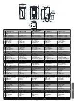
Page 101: ... ELÉCTRICO SCHEMA ELETTRICO 101 12 FICHAS TÉCNICAS DESPIECES TECHNICAL SPECIFICATIONS EXPLODED DRAWINGS FICHES TÉCHNIQUES DÉCOUPES FICHAS TÉCNICAS DESMONTAGEM SCHEDA TECNICA ESPLOSI 102 12 1 DAMA H 106 12 2 LETICIA H 108 12 3 REYNA H 110 INDICE INDEX INDEX ÍNDICE INDICE FT ...

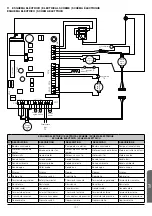
Page 102: ...d extraction de fumée Motor extracção de fumos Motore estrazione di fumi 3 Motor sinfín Geared motor Moteur vis sans fin Motor sem fim Motore coclea 4 Sonda humos Smoke probe Sonde fumées Sonda fumos Sonda fumi 5 Sonda ambiente Ambient probe Sonde ambiante Sonda ambiente Sonda ambiente 6 Sonda agua Water probe Sonde eau Sonda água Sonda acqua 7 Display Display Display Display Display 8 Debimetro P...

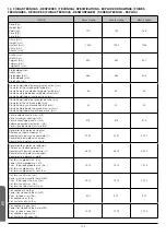
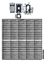
Page 103: ...ndimiento en potencia nominal Efficiency at nominal power Rendement à puissance nominale Rendimento em potência nominal Rendimento in potenza nominale 91 91 91 91 91 91 Rendimiento en potencia reducida Efficiency at reduced power Rendement à puissance réduite Rendimento em potência reduzida Rendimento in potenza ridotta 96 13 96 13 96 13 Pot térmica global máx Kw Power thermal global max kW Puiss ...

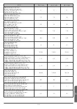
Page 104: ... h 16 3 6 2 16 3 6 2 16 3 6 2 Tiro recomendado a potencia útil máx Pa Recommended draw at maximum usable power Pa Tirage recommandé à puissance utile max Pa Tiragem recomendada para potência útil máx Pa Tiraggio raccomandato a potenza utile massima Pa 12 12 12 Tiro recomendado a potencia útil mín Pa Minimum usable power recommended draw Pa Tirage recommandé à puissance utile min Pa Tiragem recomen...

Page 105: ...co fumos potência nominal Caudale di massa dei fumi potenza nominale 12 3 12 3 12 3 Caudal másico humos potencia reducida Smoke mass flow at reduced power Débit massique des fumées puissance réduite Caudal mássico fumos potência reduzida Caudale di massa dei fumi potenza ridotta 7 3 7 3 7 3 Tª Humos potencia nominal Smoke temperature at nominal power Température des fumées puissance nominale Tempe...

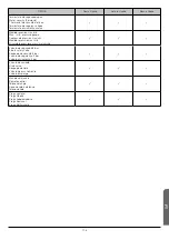
Page 106: ...pression max min Medidor pressão máx min Misuratore pressione massima minima Válvula de seguridad 3 bar 3 bars safety valve Soupape de sécurité 3 bar Válvula de segurança 3 bar Valvola di sicurezza 3 bar Válvula de vaciado Drain valve Soupape de vidé Válvula de esvaziamento Valvola di spurgo Mando a distancia Remote control Télécommande Cocomando à distância Telecomando Progr semanal Progr Weekly ...

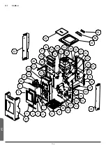
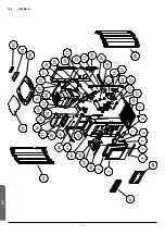
Page 107: ...106 12 1 DAMA H FT ...

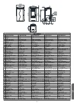
Page 108: ...r Support motoréducteur Suporte motoredutor Supporto motoriduttore 26 Conjunto sinfín Screw conveyor set Ensemble sans fin Conjunto sem fim Elementi coclea 27 Vaso de expansion Expansion vessel Vase d expansion Vaso de expansão Vaso di espansione 28 Chapa sujeta vaso expansion Expansion vessel holder plate Plaque support vase d expansion Chapa suporte vaso expansão Lamiera supporto vaso di espansi...

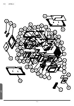
Page 109: ...108 12 2 LETICIA H FT ...

Page 110: ...de expansion Expansion vessel Vase d expansion Vaso de expansão Vaso di espansione 28 Chapa sujeta vaso expansion Expansion vessel holder plate Plaque support vase d expansion Chapa suporte vaso expansão Lamiera supporto vaso di espansione 29 Chasis trasero Rear chassis Châssis arrière Chassi traseiro Chassis posteriore 30 Tubo salida de humos Smoke outtake Tuyau sortie de fumées Tubo saída fumo T...

Page 111: ...110 12 3 REYNA H FT ...

Page 112: ... Supporto motoriduttore 26 Conjunto sinfín Screw conveyor set Ensemble sans fin Conjunto sem fim Elementi coclea 27 Vaso de expansion Expansion vessel Vase d expansion Vaso de expansão Vaso di espansione 28 Chapa sujeta vaso expansion Expansion vessel holder plate Plaque support vase d expansion Chapa suporte vaso expansão Lamiera supporto vaso di espansione 29 Chasis trasero Rear chassis Châssis ...

Page 113: ...3 2 CONDITIONS DE NON ACCEPTATION DE LA GARANTIE 115 13 3 SONT EXCLUS DE LA GARANTIE 115 13 4 EXCLUSION DE RESPONSABILITÉ 115 13 5 INDICATION EN CAS DE FONCTIONNEMENT ANORMAL DU MODÈLE 115 13 GARANTIA 116 13 1 CONDIÇÕES PARA RECONHECER COMO VÁLIDA A GARANTIA 116 13 2 CONDIÇÕES PARA RECONHECER COMO NÃO VÁLIDA A GARANTIA 116 13 3 FICAM EXCLUÍDOS DA GARANTIA 116 13 4 EXCLUSÃO DE RESPONSABILIDADE 116 ...

Page 114: ...l a las cargas de leña superiores a lo especificado o uso de combustibles no autorizados según prescripciones del presente manual Daños derivados de agentes atmosféricos químicos electroquímicos ineficacia o falta de conducto de humos y otras causas que no dependan de la fabricación del aparato Todos los daños derivados del transporte se recomienda revisar minuciosamente los productos en el moment...

Page 115: ...ncorrect fuel loads over the one specified or unauthorized use of fuels as prescribed in this manual Damage resulting from atmospheric chemical and electrochemical agents as well as the inefficiency or lack of flue pipe and other causes not deriving from the manufacture of the equipment All transport damages it is recommended to check carefully the product when you receive it should be reported im...

Page 116: ...bustibles non autorisés selon les prescriptions du présent manuel Dommages à cause d agents atmosphériques chimiques électrochimiques inefficacité ou manque de conduit de fumées et des autres causes qui ne sont pas dépendantes de la fabrication de l appareil Tous les dommages à cause du transport on recommande une analyse détaillée des produits au moment de la réception devront être immédiatement ...

Page 117: ...ncipalmente das cargas de lenha superiores ao especificado ou uso de combustíveis não autorizados segundo as prescrições do presente manual Danos derivados de agentes atmosféricos químicos electroquímicos ineficácia ou ausência de conduta de fumos bem como outras causas que não dependam do fabrico do aparelho Todos os danos derivados do transporte recomenda se rever minuciosamente os produtos no m...

Page 118: ...difiche o manipolazioni errate e soprattutto carichi di legna superiore a quello specificato o l uso di combustibili non autorizzati come prescritto in questo manuale Danni derivanti da agenti atmosferici chimici o elettrochimici inefficienza o mancanza di tubo di scarico fumi e di altre cause che non dipendano dalla fabbricazione dell apparecchio Tutti i danni del trasporto si consiglia di revisa...

Page 119: ...ut previous notice Les données et modèles inclus dans ce manuel ne sont pas contraignants La sociète se réserve le droit d apporter les modifications et améliorations sans aucun préavis Os dados e modelos incluídos neste manual não são vinculantes A empresa reserva se o direito de fazer alterações e melhorias sem nenhum pré aviso I dati e i modelli inclusi in questo manuale non sono vincolanti La ...

Page 120: ...a obter mais informações S il vous plaît n hésitez pas à contacter votre distributeur si vous avez d autres questions Per favore non esitate a contattare il vostro distributore per altri informazioni V 170315 Descarga este manual en versión digital Download this manual in digital version Télécharger ce manuel en version digitale Scarica questo manuale in versione digitale Baixe o manual em versão ...

Reviews: