


Precautions specific to fan assemblies
Observe the following precautions when replacing fan assemblies.
NOTE
Each fan assembly contains two fans for a total of four fans for two installed fan assemblies. The device requires 3 fans out of 4
functioning fans for operation. If hot-swapping a fan assembly, be sure to have the replacement fan assembly ready to install
before removing a faulty fan assembly and replace as soon as possible.
NOTE
If a fan assembly has failed, do not remove it from chassis unless a FRU is available for replacement. If the slot is left empty for
an extended time period, this could cause chassis air-leakage and overheating.
NOTE
Make sure that captive screws securing fan assemblies to chassis are tightened. If not, high pressure from fan operation may
unseat fan from chassis connectors.
Fan assembly fault indicators
Use one of the following methods to determine if a fan assembly is faulty:
•
Check the fan status LED.
–
Steady amber - fan assembly has a failure (full or partial).
–
Slow-flashing amber (on 2 seconds, then off 2 seconds) - fan assembly is not seated correctly or is faulty.
–
Fast-flashing amber (on ½ second, then off ½ second) - environmental range exceeded.
•
Enter
fanShow
. If status of fan assembly displays absent or faulty, check if assembly is seated in chassis. If it is, power supply
could be faulty or is not receiving power for some reason.
•
Enter
sensorShow
to determine if a fan is running above average temperatures of other installed fan(s).
•
Enter
errDump
to display the system error log.
For more information on LED operation, refer to
Interpreting fan assembly LEDs
For output examples and additional information on Fabric OS commands, refer to
on page 115 and the
Brocade Fabric OS Command Reference
.
For more information about error messages, refer to the
Brocade Fabric OS Message Reference
.
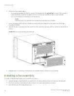
Fan assembly task guide
This section contains a guide to more complete, detailed steps in this section for installing or replacing fan assemblies when the chassis
is running (hot swap) or must be powered off (cold swap). References are provided to the more detailed removal and installation steps for
further information.
NOTE
Each fan assembly contains 2 fans for a total of 4 fans for two installed fan assemblies. The chassis requires 3 fans out of 4
functioning fans for operation. If hot-swapping a fan assembly, be sure to have the replacement fan assembly ready to install
before removing a faulty fan assembly and replace as soon as possible.
Precautions specific to fan assemblies
Brocade X6-4 Director Hardware Installation Guide
192
53-1004106-07
Summary of Contents for X6-4
Page 12: ...Brocade X6 4 Director Hardware Installation Guide 12 53 1004106 07...
Page 20: ...Brocade X6 4 Director Hardware Installation Guide 20 53 1004106 07...
Page 28: ...Brocade X6 4 Director Hardware Installation Guide 28 53 1004106 07...
Page 64: ...Brocade X6 4 Director Hardware Installation Guide 64 53 1004106 07...
Page 86: ...Brocade X6 4 Director Hardware Installation Guide 86 53 1004106 07...
Page 102: ...Brocade X6 4 Director Hardware Installation Guide 102 53 1004106 07...
Page 130: ...Brocade X6 4 Director Hardware Installation Guide 130 53 1004106 07...
Page 140: ...Brocade X6 4 Director Hardware Installation Guide 140 53 1004106 07...
Page 166: ...Brocade X6 4 Director Hardware Installation Guide 166 53 1004106 07...
Page 196: ...Brocade X6 4 Director Hardware Installation Guide 196 53 1004106 07...
Page 200: ...Brocade X6 4 Director Hardware Installation Guide 200 53 1004106 07...
Page 204: ...Brocade X6 4 Director Hardware Installation Guide 204 53 1004106 07...
Page 210: ...Brocade X6 4 Director Hardware Installation Guide 210 53 1004106 07...
Page 224: ...Brocade X6 4 Director Hardware Installation Guide 224 53 1004106 07...
Page 238: ...Brocade X6 4 Director Hardware Installation Guide 238 53 1004106 07...