


Installing a blade
NOTE
Read all of the instructions for replacing the CP blade before beginning the procedure. Make sure that the same version of
Fabric OS is installed on both CP blades. Using different versions is not supported and may cause malfunctioning. If the
replacement CP blade has a different version of Fabric OS, bring both blades to the same firmware version. Once you have
installed the replacement CP blade, determine the version of firmware on the replacement CP blade and upgrade it if
necessary.
Complete the following steps to install a CP blade.
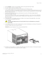
1. If a protective sleeve is covering the blade connectors remove the sleeve.
2. Rotate the ejector handles away from center of blade completely - approximately 45 degrees. Do not support the blade using
ejector handles. Orient the blade so that the handles are toward you and the flat metal side is facing down.
3. Follow these steps to insert the blade into the slot.
a)
Align the blade in the slot with the flat metal side of the blade at the bottom (blade power and status LEDs are on the left).
b) Carefully push the blade into the slot using your thumbs or fingers on the blade faceplate.
CAUTION
To avoid damaging blade and chassis, do not push the blade into a slot or pull the blade from a slot using the
ejector handles.
When the blade face is about 2.54 cm (1 in.) from the chassis, you should feel resistance as the blade connectors meet the
backplane connectors.
c)
Continue pushing with your thumbs or fingers until the ejectors move in towards the blade slightly indicating that the
connectors are engaged.
d) Simultaneously push both ejector handles in towards the blade center with even pressure until the blade completely seats in
the slot.
NOTE
As you move the handles, you will hear connectors engaging the backplane connector and possibly a slight
popping noise. This is normal and is due to the dense backplane.
4. Tighten the captive screw for each ejector using a #1 Phillips screwdriver.
As blade seats completely, amber blade status and green blade power LEDs illuminate.
NOTE
Be sure that captive screws are tightened. If not, high pressure from fan operation may unseat blade from chassis
connectors.
5. Observe the blade power and status LEDs and verify the following:
a)
The amber status LED on the blade illuminates until POST completes for the blade. The LED remains amber until the
blade has gained sync with the active CP. This can take a few minutes to complete depending on the configuration. If the
status LED remains amber for an extended period, the board may not be properly seated in the backplane or the board
may be faulty.
b) The power LED on the port blade should displays a steady green. If it does not turn on, ensure that the blade is firmly
seated and blade ejector screws are tightened.
6. Connect the cables to the new CP blade.
7. Remain logged in to the active CP and continue to
Verifying and synchronizing firmware on blades
on page 159.
Replacing a CP blade
Brocade X6-4 Director Hardware Installation Guide
158
53-1004106-07
Summary of Contents for X6-4
Page 12: ...Brocade X6 4 Director Hardware Installation Guide 12 53 1004106 07...
Page 20: ...Brocade X6 4 Director Hardware Installation Guide 20 53 1004106 07...
Page 28: ...Brocade X6 4 Director Hardware Installation Guide 28 53 1004106 07...
Page 64: ...Brocade X6 4 Director Hardware Installation Guide 64 53 1004106 07...
Page 86: ...Brocade X6 4 Director Hardware Installation Guide 86 53 1004106 07...
Page 102: ...Brocade X6 4 Director Hardware Installation Guide 102 53 1004106 07...
Page 130: ...Brocade X6 4 Director Hardware Installation Guide 130 53 1004106 07...
Page 140: ...Brocade X6 4 Director Hardware Installation Guide 140 53 1004106 07...
Page 166: ...Brocade X6 4 Director Hardware Installation Guide 166 53 1004106 07...
Page 196: ...Brocade X6 4 Director Hardware Installation Guide 196 53 1004106 07...
Page 200: ...Brocade X6 4 Director Hardware Installation Guide 200 53 1004106 07...
Page 204: ...Brocade X6 4 Director Hardware Installation Guide 204 53 1004106 07...
Page 210: ...Brocade X6 4 Director Hardware Installation Guide 210 53 1004106 07...
Page 224: ...Brocade X6 4 Director Hardware Installation Guide 224 53 1004106 07...
Page 238: ...Brocade X6 4 Director Hardware Installation Guide 238 53 1004106 07...