


Preparing for replacement
Use the following steps to prepare the system for CP blade replacement by backing up the device configuration, connecting to the device
with a serial connection, determining the active CP blade, failing over the blade to replace, determining the firmware version on the active
blade, and uploading configuration data to the active blade.
1. Back up the device configuration before you replace a CP blade by uploading various device configuration files using a Telnet
connection and saving them to a host computer. Before you upload a configuration file, verify that you can reach the FTP server
from the device.
Perform the following steps:
a)
Enter the
configupload -all
command, specifying a file name for saving configuration data.
This saves all system configuration data including chassis and switch configuration for all logical switches to the file name
specified. For more information, refer to the
Brocade Fabric OS Command Reference
.
b) Enter the
configupload -vf
command, specifying a file name, when prompted, for saving configuration data.
This saves the backbone virtual fabric data to the file name specified. For more information, refer to the
Brocade Fabric OS
Command Reference
.
c)
In a FICON environment, log in as root and enter
configupload --map
to upload port-to-area mapping information.
Specify a folder name, when prompted.
This command saves the port-to-area addressing mode configuration files to the folder specified. Be sure to upload the
configuration using the
-map
option for a FICON-enabled device if port-bound addressing is used. For more information,
refer to the
Brocade Fabric OS Command Reference
.
2. Connect to the device and log in as
admin
, using a serial console connection.
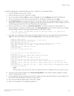
3. Enter
haShow
to determine which CP blade is active.
Chassis_1:admin> haShow
Local CP (Slot 1, CP1) : Active
Remote CP (Slot 2, CP0) : Standby, Healthy
HA Enabled, Heartbeat Up, HA State Synchronized
4. Enter all remaining commands from the serial console for the active CP blade, unless otherwise indicated. For more information
about commands, refer to the
Brocade Fabric OS Command Reference
.
5. If the active CP blade is faulted, automatic fail over to the standby CP blade should have occurred. Perform the following steps:
a)
Confirm that the standby CP blade is active using the
haShow
command.
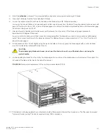
b) Power off the faulted CP blade by loosening the captive screws on both ejector handles on the blade using a #1 Phillips
screwdriver. This disconnects power from the blade. The spring-loaded captive screwswill pop out from the slot .63 cm (.
25 in.) when fully disengaged.
c)
Log into the now active CP blade.
d) Skip to step 8.
If automatic fail over has not occurred, manually fail over the faulty blade by loosening the captive screws on both ejector
handles. As the screws loosen, the blade fails over and the amber status LED will illuminate. Log into the standby CP blade, and
skip to step 8.
6. If both CP blades are healthy and you want to replace the standby CP blade, log in to the active CP blade and skip to step 8.
Preparing for replacement
Brocade X6-4 Director Hardware Installation Guide
53-1004106-07
155
Summary of Contents for X6-4
Page 12: ...Brocade X6 4 Director Hardware Installation Guide 12 53 1004106 07...
Page 20: ...Brocade X6 4 Director Hardware Installation Guide 20 53 1004106 07...
Page 28: ...Brocade X6 4 Director Hardware Installation Guide 28 53 1004106 07...
Page 64: ...Brocade X6 4 Director Hardware Installation Guide 64 53 1004106 07...
Page 86: ...Brocade X6 4 Director Hardware Installation Guide 86 53 1004106 07...
Page 102: ...Brocade X6 4 Director Hardware Installation Guide 102 53 1004106 07...
Page 130: ...Brocade X6 4 Director Hardware Installation Guide 130 53 1004106 07...
Page 140: ...Brocade X6 4 Director Hardware Installation Guide 140 53 1004106 07...
Page 166: ...Brocade X6 4 Director Hardware Installation Guide 166 53 1004106 07...
Page 196: ...Brocade X6 4 Director Hardware Installation Guide 196 53 1004106 07...
Page 200: ...Brocade X6 4 Director Hardware Installation Guide 200 53 1004106 07...
Page 204: ...Brocade X6 4 Director Hardware Installation Guide 204 53 1004106 07...
Page 210: ...Brocade X6 4 Director Hardware Installation Guide 210 53 1004106 07...
Page 224: ...Brocade X6 4 Director Hardware Installation Guide 224 53 1004106 07...
Page 238: ...Brocade X6 4 Director Hardware Installation Guide 238 53 1004106 07...