


NOTE
For information about the transceivers that are qualified for this Brocade device, refer to the "Installing Transceivers and Cables"
section.
Removing a blade
•
Before removing any cables from a blade, note the cable order (identify each cable by its physical port).
•
It is a good practice to create a table of cable to port mapping for reference.
•
If multiple blades are being replaced, replace one blade at a time.
Use the following steps to remove a port or extension blade from the unit while system power is on. This procedure is applicable for all
the port and extension blades supported on the device.
1. Remove the chassis door.
2. Check the blade power and status LEDs and port status LEDs on the front of each blade to identify any possible problems.
3. Before replacing a blade, establish a Telnet or console connection to determine a failure and verify operation after replacement.
Use the
switchShow
and
slotShow
commands to view the status of the blades.
4. Check for adequate cable slack. Ensure there is plenty of cable slack to remove a blade without cable obstruction.
5. Ensure that the part number on the unit being replaced matches the replacement part number. The
chassisShow
command
displays information about the blades, including part numbers (
xx-xxxxxxx-xx
), serial numbers, and additional status.
6. Ensure that traffic is not flowing through the blade (port status LED should be off) prior to disconnecting cables.
7. Disconnect all cables and remove transceivers from the blade.
8. If removing an extension blade, perform the following steps:
a)
Delete all fciptunnel configurations using the
portcfg fciptunnel slot/vePort delete
command.
b) Delete all IP Routes defined on the blade to be removed using the
portcfg iproute delete
command.
c)
Delete all IP interfaces (IPIFs) defined on the blade using the
portcfg ipif slot/geX delete
command.
d) If logical switches are used on the switch, move all blade ports back to the default logical switch. Refer to the
lscfg
command in the
Brocade Fabric OS Command Reference
for details.
NOTE
If you are removing the extension blade to install in a different slot, you must remove configuration using the preceding
steps, then reconfigure the blade in the new slot. If you move the blade without performing these steps and the blade
faults, you must move the blade to the original slot and remove configuration.
9. Loosen the captive screws for both ejector handles on the blade using a #1 Phillips screwdriver.
Loosening the screws initiates a hot-swap request and disconnects power from the blade. The spring-loaded captive screws will
pop out from the slot .63 cm (.25 in.) when fully disengaged. Do not eject the blade using blade handles until screws disengage
from slot and the power LED is off.
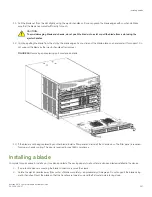
10. Grasp both ejector handles and simultaneously pull them away from the center of the blade using equal pressure to
approximately 45 degrees (fully open).
As you move the handles, you will hear connectors disengaging from the backplane connector and possibly a slight popping
noise. This is normal and is due to the dense backplane. The blade will move out approximately 1.27 cm (.5 in.) from the slot
when fully disengaged.
Removing a blade
Brocade X6-4 Director Hardware Installation Guide
136
53-1004106-07
Summary of Contents for X6-4
Page 12: ...Brocade X6 4 Director Hardware Installation Guide 12 53 1004106 07...
Page 20: ...Brocade X6 4 Director Hardware Installation Guide 20 53 1004106 07...
Page 28: ...Brocade X6 4 Director Hardware Installation Guide 28 53 1004106 07...
Page 64: ...Brocade X6 4 Director Hardware Installation Guide 64 53 1004106 07...
Page 86: ...Brocade X6 4 Director Hardware Installation Guide 86 53 1004106 07...
Page 102: ...Brocade X6 4 Director Hardware Installation Guide 102 53 1004106 07...
Page 130: ...Brocade X6 4 Director Hardware Installation Guide 130 53 1004106 07...
Page 140: ...Brocade X6 4 Director Hardware Installation Guide 140 53 1004106 07...
Page 166: ...Brocade X6 4 Director Hardware Installation Guide 166 53 1004106 07...
Page 196: ...Brocade X6 4 Director Hardware Installation Guide 196 53 1004106 07...
Page 200: ...Brocade X6 4 Director Hardware Installation Guide 200 53 1004106 07...
Page 204: ...Brocade X6 4 Director Hardware Installation Guide 204 53 1004106 07...
Page 210: ...Brocade X6 4 Director Hardware Installation Guide 210 53 1004106 07...
Page 224: ...Brocade X6 4 Director Hardware Installation Guide 224 53 1004106 07...
Page 238: ...Brocade X6 4 Director Hardware Installation Guide 238 53 1004106 07...