


DANGER
For safety reasons, the ESD wrist strap should contain a series 1 megaohm resistor.
CAUTION
If you do not install a module or a power supply in a slot, you must keep the slot filler panel in place. If you run the chassis
with an uncovered slot, the system will overheat.
CAUTION
Static electricity can damage the chassis and other electronic devices. To avoid damage, keep static-sensitive devices in
their static-protective packages until you are ready to install them.
CAUTION
Before plugging a cable into any port, be sure to discharge the voltage stored on the cable by touching the electrical
contacts to ground surface.
CAUTION
To avoid damaging blade and chassis, do not push the blade into a slot or pull the blade from a slot using the ejector
handles.
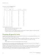
Faulty blade indicators
Confirm that you need to replace the blade before continuing. The following events may indicate that a blade is faulty:
•
The status LED on the blade is lit steady amber, or the power LED is not illuminated.
•
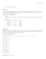
The
slotShow
command does not show that the blade is enabled.
•
errShow - Displays error log messages one at a time.
•
Any of the following messages display in the error log or "show" command output:
–
"Slot unknown" message relating to the blade slot
–
FRU: FRU_FAULTY messages for the blade
–
FAULTY (xx) with an associated (xx) code used by support
For output examples and additional information on Fabric OS commands, refer to
on page 115 and the
Brocade Fabric OS Command Reference
.
For more information about error messages, refer to the
Brocade Fabric OS Message Reference
.
Time and items required for removal and installation
The removal or installation procedure for each blade takes less than 10 minutes. Removing and restoring transceivers and cables may
take longer depending on how many must be changed. The following items are required for the blade and filler panel replacement:
•
Electrostatic discharge (ESD) grounding strap
•
Workstation computer
•
Replacement blade or filler panel
•
#1 Phillips screwdriver
•
SFP, SFP+, or SFP28 transceivers (as needed)
•
Optical and copper cables (as needed)
Time and items required for removal and installation
Brocade X6-4 Director Hardware Installation Guide
53-1004106-07
135
Summary of Contents for X6-4
Page 12: ...Brocade X6 4 Director Hardware Installation Guide 12 53 1004106 07...
Page 20: ...Brocade X6 4 Director Hardware Installation Guide 20 53 1004106 07...
Page 28: ...Brocade X6 4 Director Hardware Installation Guide 28 53 1004106 07...
Page 64: ...Brocade X6 4 Director Hardware Installation Guide 64 53 1004106 07...
Page 86: ...Brocade X6 4 Director Hardware Installation Guide 86 53 1004106 07...
Page 102: ...Brocade X6 4 Director Hardware Installation Guide 102 53 1004106 07...
Page 130: ...Brocade X6 4 Director Hardware Installation Guide 130 53 1004106 07...
Page 140: ...Brocade X6 4 Director Hardware Installation Guide 140 53 1004106 07...
Page 166: ...Brocade X6 4 Director Hardware Installation Guide 166 53 1004106 07...
Page 196: ...Brocade X6 4 Director Hardware Installation Guide 196 53 1004106 07...
Page 200: ...Brocade X6 4 Director Hardware Installation Guide 200 53 1004106 07...
Page 204: ...Brocade X6 4 Director Hardware Installation Guide 204 53 1004106 07...
Page 210: ...Brocade X6 4 Director Hardware Installation Guide 210 53 1004106 07...
Page 224: ...Brocade X6 4 Director Hardware Installation Guide 224 53 1004106 07...
Page 238: ...Brocade X6 4 Director Hardware Installation Guide 238 53 1004106 07...