3. Close the ejector handles and then tighten the thumbscrews inside each handle using the Phillips screwdriver.
4. Turn the core switch blade on by sliding the ON/OFF switch in the top handle up, to cover the thumbscrew.
5. Verify that the power LED is green (might require a few seconds). If not, ensure that the core switch blade has power and is
firmly seated and that the ejectors are in the locked position.
6. Connect the cables to the new core switch blade. If ICL cables are not used, insert EMI plugs into the cable sockets.
7. Replace the chassis door (
Removal and replacement of the chassis door
on page 83).
8. Pack the faulty core switch blade in the packaging provided with the new core switch blade, and contact the Brocade DCX
supplier to determine the return procedure.
Removal and replacement of the power supply
Use this procedure to remove and replace a power supply.
NOTE
The Brocade DCX can continue operating during the replacement if at least one 220 VAC power supply is operating or at least
two 110 VAC power supplies are working. DCX power supplies are 100-240 VAC, auto-sensing.
NOTE
A chassis with slots for eight port blades can have up to four power supplies installed. If you are adding additional power
supplies, you can use the procedures in this section under "Replacing a power supply" to install the new power supplies. Be sure
to follow steps on those procedures to enable sending notifications when the additional power supplies fail.
Time and items required
The replacement procedure for each power supply takes less than 5 minutes. A power supply unit or filler panel is required for the power
supply replacement.
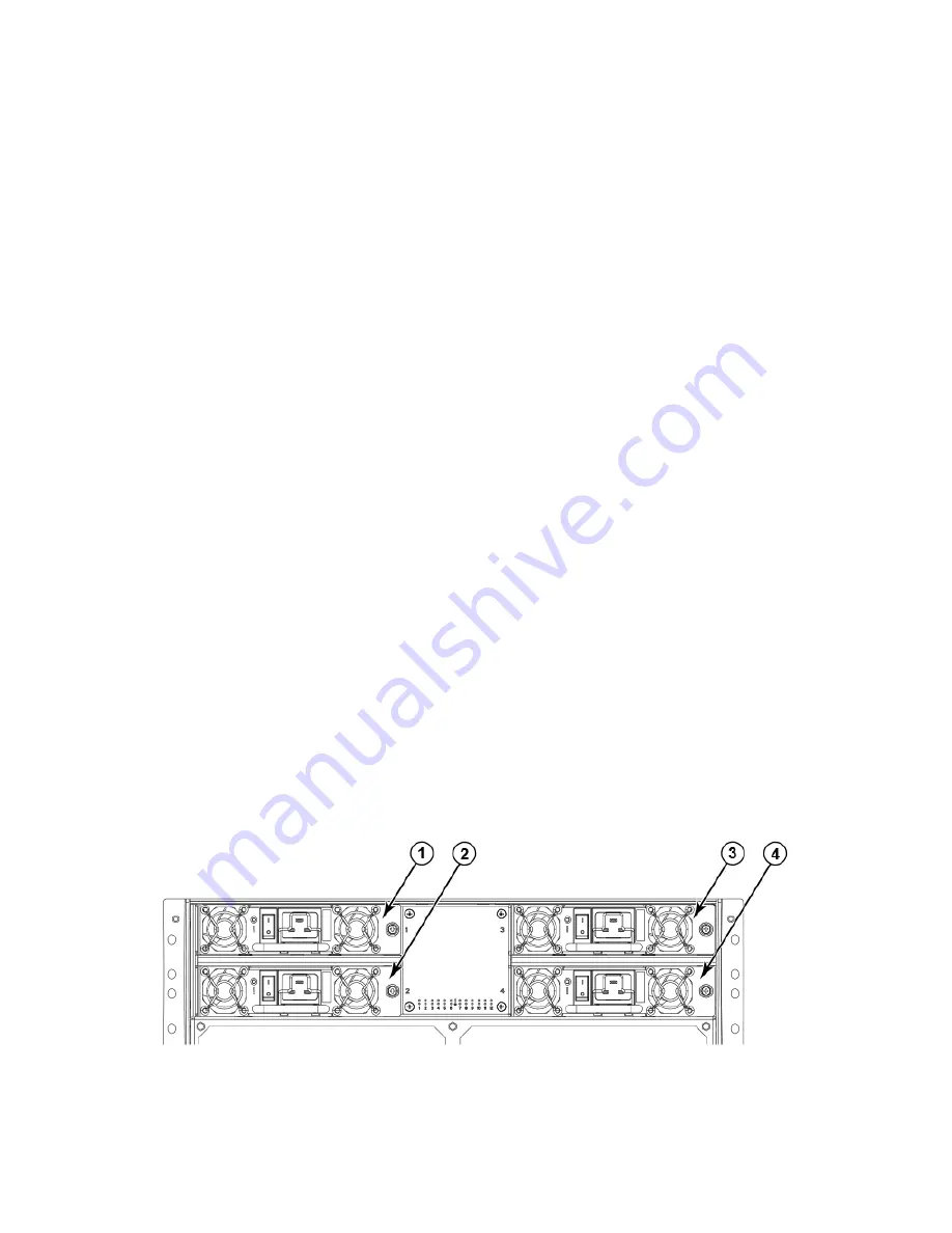
Identifying power supplies
The following figure shows the location and identification of the power supplies.
FIGURE 34
Power supply identification
1. Power supply 1 (PS1)
2. Power supply 2 (PS2)
Removal and replacement of the power supply
Brocade DCX Backbone Hardware Installation Guide
100
53-1000685-24
Summary of Contents for DCX Backbone
Page 8: ...Brocade DCX Backbone Hardware Installation Guide 8 53 1000685 24...
Page 12: ...Brocade DCX Backbone Hardware Installation Guide 12 53 1000685 24...
Page 14: ...Brocade DCX Backbone Hardware Installation Guide 14 53 1000685 24...
Page 24: ...Brocade DCX Backbone Hardware Installation Guide 24 53 1000685 24...
Page 28: ...Brocade DCX Backbone Hardware Installation Guide 28 53 1000685 24...
Page 46: ...Brocade DCX Backbone Hardware Installation Guide 46 53 1000685 24...
Page 50: ...Brocade DCX Backbone Hardware Installation Guide 50 53 1000685 24...
Page 82: ...Brocade DCX Backbone Hardware Installation Guide 82 53 1000685 24...
Page 138: ...Brocade DCX Backbone Hardware Installation Guide 138 53 1000685 24...
Page 142: ...Brocade DCX Backbone Hardware Installation Guide 142 53 1000685 24...
Page 148: ...Brocade DCX Backbone Hardware Installation Guide 148 53 1000685 24...


