


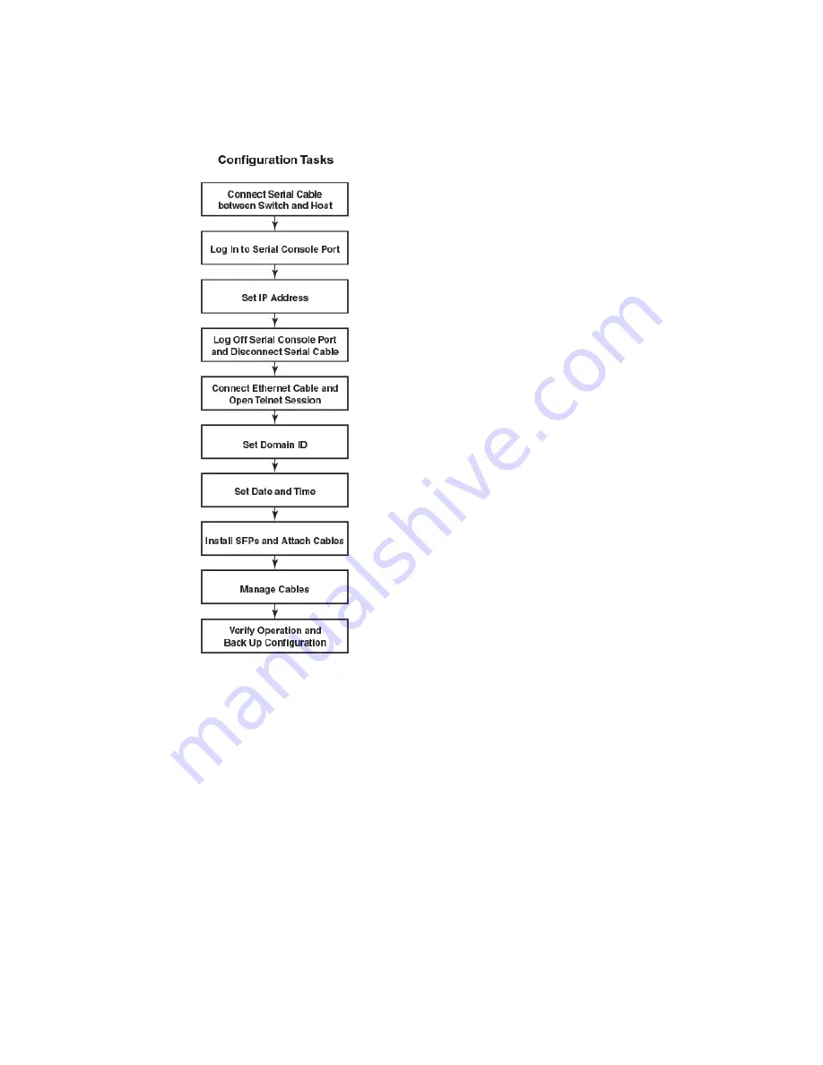
FIGURE 6
Configuration tasks
Establishing a serial connection to the Brocade DCX 8510-8
To establish a serial connection to the console port on the Brocade DCX 8510-8, complete the
following steps.
1. Verify that the Brocade DCX 8510-8 is powered on and that POST is complete by verifying that all
power LED indicators on the port, control processor, and core switch blades display a steady green
light.
2. Remove the shipping cap from the CONSOLE port on the active CP. Use the serial cable provided
with the Brocade DCX 8510-8 to connect the CONSOLE port on the active CP to a computer
workstation. The active CP blade is indicated by an illuminated (blue) LED.
Establishing a serial connection to the Brocade DCX 8510-8
36
Brocade DCX 8510-8 Backbone Hardware Reference Manual
53-1002180-08
Summary of Contents for DCX 8510-8
Page 1: ...53 1002180 08 19 September 2014 Brocade DCX 8510 8 Backbone Hardware Reference Manual ...
Page 22: ...Network manageability 22 Brocade DCX 8510 8 Backbone Hardware Reference Manual 53 1002180 08 ...
Page 34: ...Installing ICL cables 34 Brocade DCX 8510 8 Backbone Hardware Reference Manual 53 1002180 08 ...
Page 172: ...Danger Notices 172 Brocade DCX 8510 8 Backbone Hardware Reference Manual 53 1002180 08 ...