background image


©


BROBO GROUP (AUST) PTY. LTD. 

8 Fowler Rd, Dandenong South 
Victoria 3175, AUSTRALIA.


  + 61 3 9794 8751


📧


[email protected]


🖷

 + 

61 3 9794 8792 


www.brobo.com.au


PRODUCT AND MAINTENANCE MANUAL 


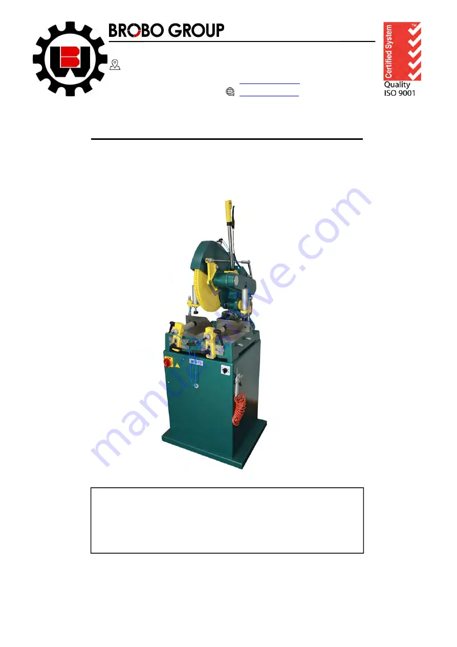
MANUAL NON-FERROUS CUTTING SAW 

MODEL No. TNF 115 (SERIES 2) 


___________________________________________________________________________________________ 
 

   Precision Drilling Machines   

   Tapping Machines   

   Multi-Head Drills   

   Tool Grinders   


   Tool Post Grinders   

   Machine Vices   

   Special Production Equipment   


   Accessories   

   Riveting Machines   

   Pedestal Grinders   

   Metal Cutting Saws   

   Linishers   


YOUR BROBO DISTRIBUTOR IS:


A.C.N.      

098 264 316 

A.B.N. 

42 098 264 316


Summary of Contents for TNF 115 2 Series

Page 1: ...SAW MODEL No TNF 115 SERIES 2 ___________________________________________________________________________________________ Precision Drilling Machines Tapping Machines Multi Head Drills Tool Grinders Tool Post Grinders Machine Vices Special Production Equipment Accessories Riveting Machines Pedestal Grinders Metal Cutting Saws Linishers YOUR BROBO DISTRIBUTOR IS A C N 098 264 316 A B N 42 098 264 3...

Page 2: ...ng Head 3 1 2 Saw Safety Guard Locking System 3 1 3 Saw Handle with Dead Man Trigger Switch 3 1 4 Power Switch Clamp Switch 3 1 5 Pneumatic Vice Clamp 3 2 Preparation for Operation 3 3 Operation Recommendations CHAPTER 4 Drawings Layouts Assembly Spare Parts 4 1 1 Main Dimensions 4 1 2 Assembly Drawings 4 1 3 Electrical Drawings CHAPTER 5 Adjustments for the Saw Unit 5 1 Changing the Blade 5 2 Adj...

Page 3: ...00 mm Bore d 30 mm Tooth Width S 3 6mm Body Thickness s 2 8mm Tooth Geometry TFZ N Triple chip tooth alternating with flat tooth with negative hook angle Number of Teeth z 120 CHARACTERISTICS Cutting of aluminium profiles mouldings plastic boards brass Suitable for angle cutting cross cutting MOTOR Power 1 5 kW Rpm 2800 rpm V Single Phase 240V TNF115 240 3 Phase 415V TNF115 415 PNEUMATIC Air press...

Page 4: ...Brobo Group brobo com au CUTTING RANGE CHART 90 100 mm 45 100 mm 90 100 mm 45 100 mm 90 100 x 190 mm 45 100 x 130 mm ...

Page 5: ... entire unit to an accessible area as close as possible to the final location Carefully remove the wooden frame surrounding the saw unit Figure 1 Once completed proceed by elevating the machine away from the pallet base using a sling harness wrapped around the cutting head of the saw Ensure that the floor is as level as possible before finally positioning the machine to the desired location FIGURE...

Page 6: ...mm 150mm pitch 9504320 Adjustable Stand 610mm 1016mm 9540330 Stand V Type Roller 9540340 Stand Flat Roller Additional Blade s Custom to Client Requirements 1 3 Minimum Requirements For the machine to function correctly the room in which the saw unit is to be installed must be in the vicinity of satisfy the following conditions 415 240V Power Supply Ambient Temperature From 10 C to 50 C Relative Hu...

Page 7: ...s accessibility to cut parts safe access for the operator The base of the fabricated stand if applicable in which the saw head rests on is anchored to the floor by 4 M12 bolts For added stability it is strongly recommended that the machine stand is fastened to the floor by using loxins not provided Required Working Area It is recommended that A B is more than 1 5m Figure 2 Saw TNF115 S2 Length Sto...

Page 8: ...pply in Australia Figure 3 1 Connection 3 pins 1 Phase b Three phase machines Figure 3 2 Connection for 5 CORE Wire System with Neutral 3 Phase c Check the power supplied motor specifications before plugging in the machine Check the terminal connection on dual voltage motor terminal box connect it accordingly to the corresponding voltage supply d If the dual motor is requested the motor is always ...

Page 9: ...se of the machine The operator must be fully aware of the position functions of all the machine s controls All those concerned must strictly adhere to ALL instructions warnings accident prevention standards in this manual The following definitions are those provided for by the EEC DIRECTIVE ON MACHINERY No 98 37 CE Danger Zone any zone in and or around a machine in which the presence of a person c...

Page 10: ...ring protection equipment as prescribed under the above stated act ALLUMINIUM IN VACUM Medium value of the sonorous level measured Lmp 75 1 dB A Value of the sonorous level in the working position measured Lmp 81 3 dB A Factor of environmental correction K 1 dB A Medium value of the correct sonorous level Lpc 74 1 dB A Value of sonorous level in the correct working position Lpc 80 3 dB A LOADED Me...

Page 11: ...experienced operator Operators should be thoroughly instructed about these hazards Only a qualified electrician should carry out regular maintenance of this system 2 2 General Requirements Lighting Insufficient lighting during the operation of the saw unit would constitute a safety hazard for the people concerned For this reason the user of the machine must provide adequate lighting in the working...

Page 12: ...be tied back or placed in a hair net Always disconnect the power supply to the machine before carrying out any maintenance work or adjustments This includes cases of abnormal operations of the machine Any maintenance work performed on the hydraulic pneumatic or coolant systems must be carried out only after the pressure in the system has been released The operator MUST NOT conduct any risky operat...

Page 13: ... Always follow safe practices inspection procedures when installing blades Please refer to section 5 1 Changing the Blade When cutting very small specimens ensure that the workpiece is not dragged behind the back fence support where it could get lodged behind the blade If the blade jams during a cut activate the emergency stop function immediately Do not continue forcing the blade through This cou...

Page 14: ...he saw also complies with the Australian Standards regarding the safeguarding general requirements for electrical equipment 2 4 1 Reference Standards MACHINE SAFETY EEC Directive No 98 37 CE Machines Directive EEC Directive No 91 368 94 68 Amends sections of EEC Directive No 98 37 CE relating to machine safety EEC Directive No 73 23 Low Voltage Directive AS4024 1 1996 Safeguarding of Machinery HEA...

Page 15: ...rocedure To adjust cutting table angles by pulling the quick release knob at middle of the clamping table 3 1 2 Saw Safety Guard Locking System The primary purpose of the saw safety guard is to protect the user from the spinning blade It also functions as a safety device to protect the operator from any broken tooth swarf or high velocity particles that might be dislodged by the cutting process Du...

Page 16: ...b clockwise to clamp the workpiece 3 1 5 Pneumatic Vice Clamps Pneumatic Vice Clamps use air actuated cylinders to operate the clamping action They are ideal for quick clamping in repetitive production operations and yet are portable economical to use on short run jobs with temporary fixturing Clamp Adjustment Adjustment is done by first releasing the levers then moving the cylinder holders to the...

Page 17: ...ressure from the pressure regulators located on the main control unit door If for any reason this pressure is not available on a continuous basis the regulator on the air service unit must be set slightly below the available line pressure the safety low pressure indicator valve needs to be reset to correspond with the newly available pressure The need to change the pressure is necessary to allow f...

Page 18: ...s flowing over the cutting teeth The rate of feed affects the quality of the final cut blade life This varies also by the material cross sectional dimensions When manually feeding the saw head keep in mind to maintain a steady continuous pressure thus avoiding work hardening on the cutting piece Avoid forcing the blade through the material as this might damage or break the blade As a rule of thumb...

Page 19: ...TE MINIMUM 600MM ALL AROUND SAFE SPACE FOR OPERATING ZONE TNF 115 S2 MAIN DIMENSIONS TITLE A4 SHEET 1 OF 4 SCALE NTS ISSUED DATE 07 02 2019 DRAWN BY ANH BROBO GROUP Address 8 Fowler Rd Dandenong VIC 3175 https brobo com au ...

Page 20: ......

Page 21: ......

Page 22: ...chip tooth alternating with flat tooth with negative hook angle LFZ flat tooth with chip limiter WZ alternate top bevel DHZ hollow face tooth flat tooth alternates with inverted V tooth WZ N alternate top bevel with negative hook angle DHZ N hollow face tooth flat tooth alternates with inverted V tooth negative hook angle LWZ alternate top bevel with chip limiter TZ triple chip tooth KON conical tooth...

Page 23: ...7640 8600 9550 250 760 1530 2290 3060 3820 4590 5350 6110 6880 7640 300 640 1270 1910 2550 3180 3820 4460 5100 5740 6370 350 550 1090 1640 2180 2730 3280 3820 4370 4900 5460 400 480 960 1430 1910 2390 2870 3340 3820 4300 4780 450 430 850 1270 1700 2120 2550 2970 3400 3820 4250 500 380 760 1150 1530 1910 2290 2680 3060 3440 3820 550 350 690 1040 1390 1740 2080 2430 2780 3120 3470 600 320 640 960 12...

Page 24: ...tislav 37 36 40 38 39 38 6 10 89 42 5 41 22 23 24 27 13 14 15 16 18 17 50 49 51 55 7 12 70 52 4 12 53 54 7 69 31 82 64 65 67 66 72 57 58 45 48 20 84 71 75 56 76 25 23 44 45 43 46 59 47 26 18 61 60 61 11 30 32 33 34 35 81 83 29 90 92 12 93 94 62 63 95 85 88 86 56 96 97 91 11 98 1 ...

Page 25: ...N 471 72x2 5 Retaining rings for shaft 43 1 16 26 06 44 1 18 26 06 LOCKING DEVICE L SHAPE LONG PIN 45 6 DIN 471 10x1 Retaining rings for shaft 46 1 13 26 06 47 1 21 26 06 48 1 10 23 05 49 1 01 13 05 SHORT PIN ROD LEVER LINK ROD MOTOR MOUNTING PLATE Parts List ITEM QTY PART NUMBER TITLE DESCRIPTION 50 4 DIN 912 M8 x 25 Cylinder Head Cap Screw 51 1 02 27 05 52 1 27 05 53 1 08 27 05 SUPPORT KEYHOLE B...

Page 26: ... 05 EXPLOSION VIEW Date 29 11 2009 Page 1 2 Author Bratislav 134 136 133 132 131 129 105 107 106 99 128 126 127 129 133 132 117 125 104 99 100 123 124 110 111 109 108 112 106 107 103 102 119 121 120 117 118 113 114 130 135 132 ...

Page 27: ...8 x 30 A 1 113 Cylinder Head Cap Screw DIN 912 M10 x 30 4 114 Washer DIN 125 A 10 5 3 117 Cylinder Head Cap Screw DIN 912 M10 x 40 1 118 Hexagon Socket Set Screw DIN 913 M8 x 20 1 119 Hex Nut DIN 934 M8 2 120 Hexagon Socket Set Screw DIN 913 M8 x 25 2 121 INSERT 16 01 06 1 123 Countersunk Screw DIN 7991 M4 x 12 6 124 CLAMP HOLDER SUPPORT 01 18 01A 06 2 125 Cylinder Head Cap Screw DIN 912 M6 x 25 1...

Page 28: ...MOST ZETA Sklop šnapera E 04 05 EXPLOSION VIEW Date 29 11 2009 Page 1 2 Author Bratislav 5 1 3 2 4 ...

Page 29: ...05 EXPLOSION VIEW Date 29 11 2009 Page 2 2 Author Bratislav Parts List DESCRIPTION TITLE PART NUMBER QTY ITEM CAM 03 23 06 1 1 01 23 06 1 2 SPRING Opruga šnapera 1 3 Spring Type Straight Pin ISO 8752 3 x 30 1 4 HANDLE Ručka M10 1 5 ...

Page 30: ...ECTION SYSTEM UNLESS NOTED 3RD ANGLE ANGULARITY TOLERANCE 0 7 CONCENTRICITY 0 1 mm ROUGH MED FINE S FINE POLISH LAP METRIC Size To Mach Cast 6 mm 0 1 0 5 30 mm 0 2 1 0 100 mm 0 3 1 5 300 mm 0 5 2 0 1000 mm 0 6 3 0 2000 mm 1 2 5 0 INCLUDES STRUCTURAL STEEL WORK REMOVE ALL BURRS AND SHARP EDGES BY 0 3 x 45 UNLESS OTHERWISE STATED COMMERCIAL STOCK SIZES EXCEPTED AND UNLESS OTHERWISE NOTED TOLERANCES ...

Page 31: ...E REMOVE ALL BURRS AND SHARP EDGES BY 0 3 x 45 UNLESS OTHERWISE STATED METRIC Size To Mach Cast 6 mm 0 1 0 5 30 mm 0 2 1 0 100 mm 0 3 1 5 300 mm 0 5 2 0 1000 mm 0 6 3 0 2000 mm 1 2 5 0 INCLUDES STRUCTURAL STEEL WORK LAP POLISH S FINE FINE MED ROUGH 0 1 mm CONCENTRICITY 0 7 ANGULARITY TOLERANCE DRAWING PRACTICE TO AS 1100 PROJECTION SYSTEM UNLESS NOTED 3RD ANGLE 50 N12 25 N11 12 5 N10 6 3 N 9 3 2 N...

Page 32: ...of the three fixing screws 3 Remove the lower blade protection cover D to facilitate the removal of the blade from its seat E 4 Remove the shaft cover Insert a 17mm spanner to remove the blade counter plate screw 5 Using a 36mm spanner loosen the blade counter plate screw in a clockwise direction Keeping in place the contrast spanner release the screw remove the counter plate to be able to remove ...

Page 33: ...inium Oil Cutting 20 l 9601481 Lubricator 9615680 5 4 1 Lubricating Oil Precautions Health Hazard Information The Brobolube lubricating fluid has no known adverse health effects Brobolube is non toxic odourless non flammable below approximately 350ºC non corrosive although it may affect some types of rubber There are no traces of sulfur chlorine phenol or nitrates found in Brobolube When comes int...

Page 34: ...g defects 6 2 Maintenance Requirements All maintenance must be carried out with the power switched off the machine in emergency stop condition To guarantee for optimum operation all spare parts must be Brobo Group originals On completion of maintenance works ensure that the replaced parts or any tools used have been removed from the machines before starting it up Any behavior not in accordance wit...

Page 35: ...sure that the machine performs cuts perpendicular to the work surface If not contact Brobo Group engineering department 7 Test that the blade is at right angles to the workpiece back fence If not contact Brobo Group engineering department 8 Regularly empty out the swarf catcher resting directly above the compensation tank of any offcuts swarf that has collected during the numerous cutting cycles ...

Page 36: ...rkpiece after cutting as it might be very hot Noise Low Under no load testing the noise level measured is below 85 dB A If the noise level becomes too high during a cutting cycle stop the process inspect for the problem if any are present Substance Low Care must be taken as some coolants may be harmful or cause allergic reactions Please read the labels carefully Keep the work area clean regularly ...

Page 37: ...s arisen due to normal wear and tear on the goods 1 5 The Supplier is under no obligation under this warranty where the Customer has failed to observe the terms of payment for the goods or any other obligation imposed by the terms and conditions of this warranty 1 6 In the event that the Supplier is supplying goods which have been manufactured by third parties the Customer shall be entitled to the...

Reviews: