


4. Tighten all the 8-32 x 5/16-in. screws to a torque of 15 in-lb (17 cm-kg).
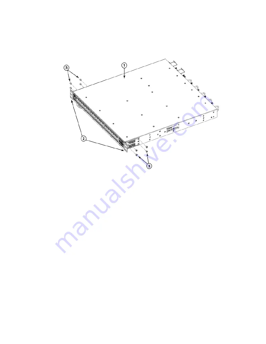
FIGURE 4
Attaching the front brackets
1.
The Brocade device
2.
Front brackets
3.
Screws, 8-32 x 5/16-in., flathead Phillips
Attaching the bracket extensions to the device
Complete the following steps to attach the extension brackets to the device. There are medium and long extension brackets that you can
use for this step.
1. Select the proper length bracket extension for your rack depth.
2. Position the right bracket extension along the side of the device as shown in
.
3. Insert four 8-32 x 5/16-in. flathead screws through the vertically aligned holes in the bracket extension and then into the holes
on the side of the device. Use the upper and lower screw holes, leaving the center holes empty.
4. Repeat step 2 and step 3 to attach the left bracket extension to the left side of the device.
Installing the Universal Four-Post Rack Kit (XBR-R000296)
Brocade G630 Hardware Installation Guide
28
53-1005235-02
Summary of Contents for Brocade G630
Page 10: ...Brocade G630 Hardware Installation Guide 10 53 1005235 02 ...
Page 22: ...Brocade G630 Hardware Installation Guide 22 53 1005235 02 ...
Page 48: ...Brocade G630 Hardware Installation Guide 48 53 1005235 02 ...
Page 72: ...Brocade G630 Hardware Installation Guide 72 53 1005235 02 ...
Page 88: ...Brocade G630 Hardware Installation Guide 88 53 1005235 02 ...
Page 96: ...Brocade G630 Hardware Installation Guide 96 53 1005235 02 ...
Page 100: ...Brocade G630 Hardware Installation Guide 100 53 1005235 02 ...


