1
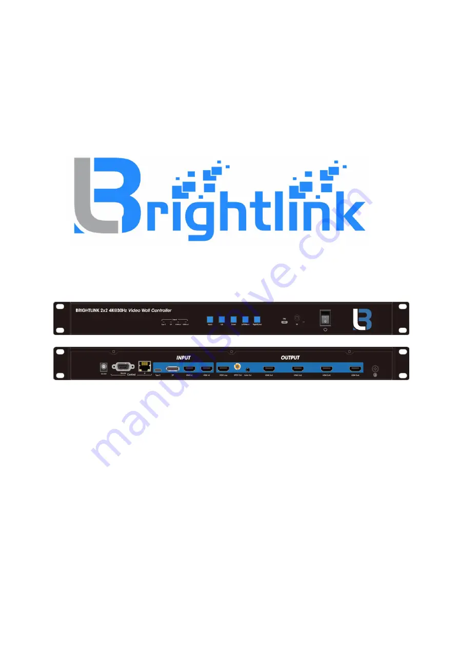
BRIGHTLINK HDMI 2X2 4K Video Wall Controller
with Mixed inputs
MODEL : BL-VW22-4K30
Operating Instruction
BRIGHTLINKAV.COM
Page 1: ...1 BRIGHTLINK HDMI 2X2 4K Video Wall Controller with Mixed inputs MODEL BL VW22 4K30 Operating Instruction BRIGHTLINKAV COM ...
Page 2: ... 7 6 INFO query information interface 21 7 7 Basic information interface 22 8 Web Control 22 8 1 Interface Introduction 24 8 2 Login Test 24 8 3 Splicing interface 25 8 4 Mirror interface 26 8 5 Edge interface 27 8 6 Menu interface 27 8 7 EDID interface 28 8 8 Network interface 29 8 9 System interface 29 9 RS232 30 10 Audio 31 10 1 HDMI audio output 31 10 2 Audio separation output 31 11 Firmware u...
Page 3: ...make changes in the hardware packaging and any accompanying documentation without prior written notice 3 SPECIFICATIONS Operating Temperature Range 0 to 40 C 32 to 104 F Operating Humidity Range 10 to 90 RH no condensation Output Video Format Supported 1080P60 720P60 1920X1200 1366X768 4K30HZ Supported input resolution The maximum input resolution supported by HDMI is 3840x2160 60hz The maximum in...
Page 4: ...ted Press the Left Menu and Right Enter button together for 5 seconds to reset the system Long press the UP and DOWN button The device will loop through the output resolution Rear Panel 1 Power input port 2 RS232 IP Control 3 HDMI Inputs Type C DP 2x HDMI in 4 HDMI Outputs HDMI Loop SPDIF Audio 4x HDMI out 6 CONNECTING AND OPERATING 1 Connect the sources into the video wall controller and Press th...
Page 5: ...HDMI 1 8 Menu 9 UP Down Left Menu Right Enter OK Right Enter 10 Display and hide OSD menu 11 Return to menu interface 12 1 4 select the input source IN1 IN4 Note 1 Right Enter means that when you select to the Right you are applying the functionality of the option on the Righ 7 1 Video switching operation The OSD display interface of video switching only shows four output channels and the current ...
Page 6: ...in menu is 1 switching video signal source 2 EDID settings 3 Audio settings 4 Setup parameter settings 5 INFO query Note the number 1 5 represents the first subitem of the five projects Operation Description Use the up and down to select the Left Menu button to return to the previous projects and Right Enter to confirm the option Video includes five subitem Switching Splicing Mirror Edge Set Forma...
Page 7: ...and down button to select the In input port the bottom color of the selected input port becomes red and the Selected Symbol is displayed 5 Click the ENTER button to confirm that the video switch is complete 7 2 2 Wall pattern It can perform fixed video wall or cascade video wall Settings on the output video which has two setting options in this mode Preset it can set up some fixed preset video wal...
Page 8: ...wn button to select 1 x 1 and other fixed preset video wall mode 7 Click on the ENTER button to set up the video wall mode successfully Set Up H_NUM represents the total number of screens on the horizontal axis with 1 x 10 selections the default is 1 V_NUM represents the total number of screens on the vertical axis with 1 x 10 selections which defaults to 1 Cascade indicates where the device is in...
Page 9: ... and down button to select H_NUM 7 Click on the ENTER key to enter the next subitem 8 Press the up and down button to select the number of 1 and select the number of screens to set 9 Click the ENTER button the number of horizontal axis display set successfully 1 0 Set up the number of vertical display screens with the above steps and what level is the cascade 7 2 3 Mirror mode All output video can...
Page 10: ...ut image including two subitems X the margin setting between the two horizontal displays is set with the 0 600 option with a minimum unit of 2 Y vertical two screen in the middle of the margin settings there are 0 600 options to set the minimum unit of 2 The middle margin of horizontal and vertical display screen defaults to 0 Operational steps 1 In the main menu select Video to press the ENTER bu...
Page 11: ...g output port can be set one of all output port can be set and all the output port can also be set The default output resolution is Auto mode which can output the corresponding resolution according to the TV Operational steps 1 In main Menu Select Format and press ENTER to confirm 2 Press the up and down button to select the Out1 output port or option 5 ALL ALL means select all outputs 3 Click the...
Page 12: ...ct EDID in the main menu and press the ENTER button 2 Press the up and down button to select the In 1 input port the ninth option indicates the selection of all inputs 3 Click the ENTER button to enter the next sub item 4 Press the up and down button to select EDID 4K 30 5 Click on ENTER to confirm that the setup of the built in EDID 4K 30 to the input port 1 is completed 7 4 Audio control Audio h...
Page 13: ...13 Delay There are 0 250 options the unit is 10 The default settings are Unmute and delay 30 Take OUT1 as the output port and set mute mute and Delay 10 delay as examples ...
Page 14: ...ick ENTER to confirm 6 Click the Left Menu button to return to the previous submenu 7 Click Delay to enter the next submenu 8 Press the down button to select the number 10 9 Click ENTER to confirm that the output 1 port audio mute and delay settings are complete 7 5 Setup interface The setting interface can set the baud rate TCP IP parameters equipment restart and factory settings of the RS 232 of...
Page 15: ...setting The TCP IP parameter setting interface can modify the parameters such as DHCP IP subnet mask gateway DNS and so on Setting of DHCP switch On open is set for dynamic and Off closed is set for static the default DHCP is OFF Operation steps 1 Select Setup in the main menu interface and press ENTER to confirm 2 Press the up and down buttons to select TCP IP and press ENTER to enters the next s...
Page 16: ...le when the IP is modified to 192 168 1 168 press the up and down button to select IP 0 IP 1 IP 2 IP 3 to enter the next subitem You can set a value from 0 to 255 in each subitemt and the value you need to set can be quickly selected by long pressing the remote controller or the up button or down button of the panel and press the up and down button to select the 192 168 1 168 Click the ENTER butto...
Page 17: ...nfirm 3 For example when the MASK is modified to 255 255 255 0 press the up and down button in turn select MASK 0 MASK 1 the MASK 2 MASK 3 to the next item each item can be set up in 0 255 a numeric value through the long press or press the up button on the panel or down button quickly select the value you need to set press the up and down button to select 255 255 255 0 click ENTER button to confi...
Page 18: ...s the up and down button to select 192 168 1 1 click ENTER button to confirm after selected 7 5 6 Modify Domain Name Default is 144 144 144 Operational steps 1 Select Setup in the main menu interface and press ENTER to confirm 2 press the up and down button to select TCP IP and press ENTER to confirm 3 For example when the DNS is modified to 144 144 144 144 press the up and down button to select M...
Page 19: ...19 36 37 ...
Page 20: ... effective Note a if the IP set is not standard when you click Apply as shown in figure 36 the IP set will not take effect Setting IP error will be displayed and the current set parameters of DHCP IP MASK and GW will be displayed b when DHCP is opened the IP setting will not take effect as shown in figure 37 7 5 8 Reboot Restart the product with yes or no options the default is NO state Operation ...
Page 21: ...sub item 3 Press the up and down button to select No or Yes 4 Click ENTER to confirm 7 6 INFO query information interface It can query equipment information such as system information IP information System display copyright model version number and other information IP display DHCP status IP MASK GW MAC and other information Operational steps 1 Select INFO in the main menu and press ENTER to confi...
Page 22: ... OSD displays N_PCM and HDMI outputs audio mute 8 Web Control The host computer is connected to the control device through the TCP IP network port such as PC it can be controlled by GUI interface The control mode is divided into two types it can be connected with a single non networked computer for single machine control it can also be connected to the LAN to realize multi machine simultaneous con...
Page 23: ...thernet environment it is necessary to ensure that the IP segment of the host is consistent with that of the connected LAN In addition the control computer network segment needs to be changed to be consistent with the host network segment and the DHCP of the device needs to be opened After inquiring enter the IP address of the device can be entered for control ...
Page 24: ...s different in different browsers 3 If the Settings are invalid or error please refresh the page and get real time data 8 2 Login 8 2 1 Login method Default IP login enter the correct account and password to enter the interface by 192 168 1 168 Enter http sxlogin login enter the correct account and password to enter the interface Note a This web has set cookies when the password and account are co...
Page 25: ...interface is used to set up video walls or cascades 8 3 1 Interface introduction Output column number of televisions in horizontal and vertical directions and equipment cascade Input column select the video source for the wall TYPE C DP HDMI1 HDMI2 The default of the device is 2x2 video wall can also realize 1x1 1x4 4x1 2x3 3x2 3x3 and other video walls through cascade The maximum number of televi...
Page 26: ...evice 1 Operation Steps 1 Click the output section on the left mouse button to set horizon 2 vertical 3 equipment 1 The device location is 1 2 Click on the input section to select the DP input the DP input box will become blue and then click apply Device 2 operation steps 1 horizon 2 vertical 3 equipment 2 2 In the input section select the input port to connect device 2 from device 1 loop output p...
Page 27: ...0 increasing or decreasing by 2 at a time 2 Operating instructions Click on the button to adjust Click the Default button to get back to the 0 0 default margin 8 6 Menu interface 1 Interface introduction The interface is used to restart the device and restore factory settings 2 Operating instructions Click on each function button to achieve its function as shown in the figure below the bottom of t...
Page 28: ...rent input sources or the same EDID can be set for all input port EDID column There are two built in EDID 4k30 1080p There are four output EDID of HDMI1 HDMI4 and a loop out EDID 8 7 2 Operating instructions 1 Select EDID in the left navigation bar and then select the INPUT source that needs to change EDID in the INPUT bar all means select all INPUT sources The bottom of the selected INPUT source ...
Page 29: ...the following IP addresses will make gray It cannot be modified and the current IP address information can be displayed Note DHCP switch is a compound switch DHCP On and DHCP Off are two choices When Off is displayed DHCP is closed when On is displayed DHCP is open click HDCP button to switch DHCP function without clicking Apply 8 9 System interface 1 Interface description It use to change the log...
Page 30: ...y images plug in the USB to RS232 tool double click to open the software and then enter the main interface of the software as shown below Instructions 1 All instructions begin with Instruction header c d operation parameter I operation lock 2 _ means underline indispensable Primary parameter d 0 all outputs 1 X specifies outputs 1 4 secondary parameters are the same as the first ...
Page 31: ...eparation and analog audio separation only support PCM2 0 channel without compression and the maximum sampling rate is 48KHZ 2 The HDMI input When EDID is built in SPDIF digital audio separation and analog audio separation only support uncompressed PCM2 0 channel with a maximum sampling rate of 192KHZ When EDID is a copy SPDIF digital audio separation supports compressed audio dolby DTS and uncomp...
Page 32: ...nd baud rate 115200 enter A1_01 _ represents space in the port then select the program VW22_xxx_xxx_app_xxx bin in the path and click update to complete the upgrade 11 2 GUI burn 11 2 1 GUI application layer MCU burning Open the software UART_ISP exe on PC select the correct port and baud rate 115200 enter A1_01 _ represents space in the port then select the program xxxx bin in the path and click ...
Page 33: ... Web burning Open the software UART_ISP exe on the PC select the correct port baud rate 115200 enter F0_01 _for space in the port and select the program XXXX html in path and click update to complete the upgrade ...
Page 34: ...arked change in performance e The unit has been dropped or the cabinet damaged 1 Servicing Personnel Do not attempt to service the unit beyond that described in these operating instructions Refer all other servicing to authorized servicing personnel 3 Replacement parts When parts need replacing ensure the servicer uses parts specified by the manufacturer or parts that have the same characteristics...
Page 35: ...e reached LIMITED WARRANTY LIMITS AND EXCLUSIONS 1 This Limited Warranty ONLY COVERS failures due to defects in materials or workmanship and DOES NOT COVER normal wear and tear or cosmetic damage The Limited Warranty ALSO DOES NOT COVER damages which occurred in shipment or failures which are caused by products not supplied by warrantor or failures which result from accidents misuse abuse neglect ...