93
18 Troubleshooting
18.1 MDR Unit
Scenario
Detection
Resolution
Loss of recording data
1. Error light will be visible on the MDR
unit LED panel
2. Error light will be shown on the Remote
panel
3. If the sound buzzer is activated or a
sound buzzer is connected to one of
the trigger outputs, an audible alarm
can alert drivers
1. SD card is used to recover data
– see the
manual for recording options
2. Require the LED panel of the MDR or a remote
panel to always be visible to driver
3. The sound buzzer should be activated and
configured to alert drivers to errors.
System Power loss
1. Error light will be visible on the MDR
unit LED panel and power LED will turn
off
1. Vehicle Battery should be replaced if it is
suspected of malfunctioning
2. Low Voltage protection feature should be turned
on
3. Fuses may be blown and may need to be
replaced
Data Corruption due to Power loss
1. Error light will be visible on the MDR
unit LED panel and power LED will turn
off
1. MDR is powered for few minutes after power
loss to enable closure of recording files
Video Loss
1. Video loss LED will turn on which is
found on the MDR and the Remote
panel
2. If the sound buzzer is activated or a
sound buzzer is connected to one of
the trigger outputs, an audible alarm
can alert drivers
1. Cables if possible should not be installed in an
area where these can be tampered with
2. Ensure cable connectors are secure before
driving
No recording on SD or HDD
1. Error light will be visible on the MDR
unit LED panel
2. Error light will be shown on the Remote
panel
3. If the sound buzzer is activated or a
sound buzzer is connected to one of
the trigger outputs, an audible alarm
can alert drivers
1. Ensure that the Overwrite feature is turned on
2. Install 1 TB HDD or 256GB SD card
MCU failure
1. Visible Physical Damage and unable to
connect on PC
1. Retain a backup MCU for a vehicle
2. Ensure supplied USB cable is used
3. Ensure PC is fully up to date with Windows
updates and drivers are installed
Failure due to Environment
1. Error light will be visible on the MDR
unit LED panel
2. Error light will be shown on the Remote
panel
3. HDD recording cannot begin (HDD
LED not ON)
1. Driver should wait a few minutes for the internal
heater to heat the HDD to above 0°C
– this will
then start to record
Docking Station Failure
1. No visible power LED is on
1. Ensure the MCU KEY is locked
2. Ensure that wires that are being used are
protected by heat shrink
HDD inconsistent functionality (HDD Repair)
1. Error light will be visible on the MDR
unit LED panel
2. Error light will be shown on the Remote
panel
1. Customers must follow the MCU removal
procedure as stipulated in the manual
18.2 MDR Fireproof Box
•
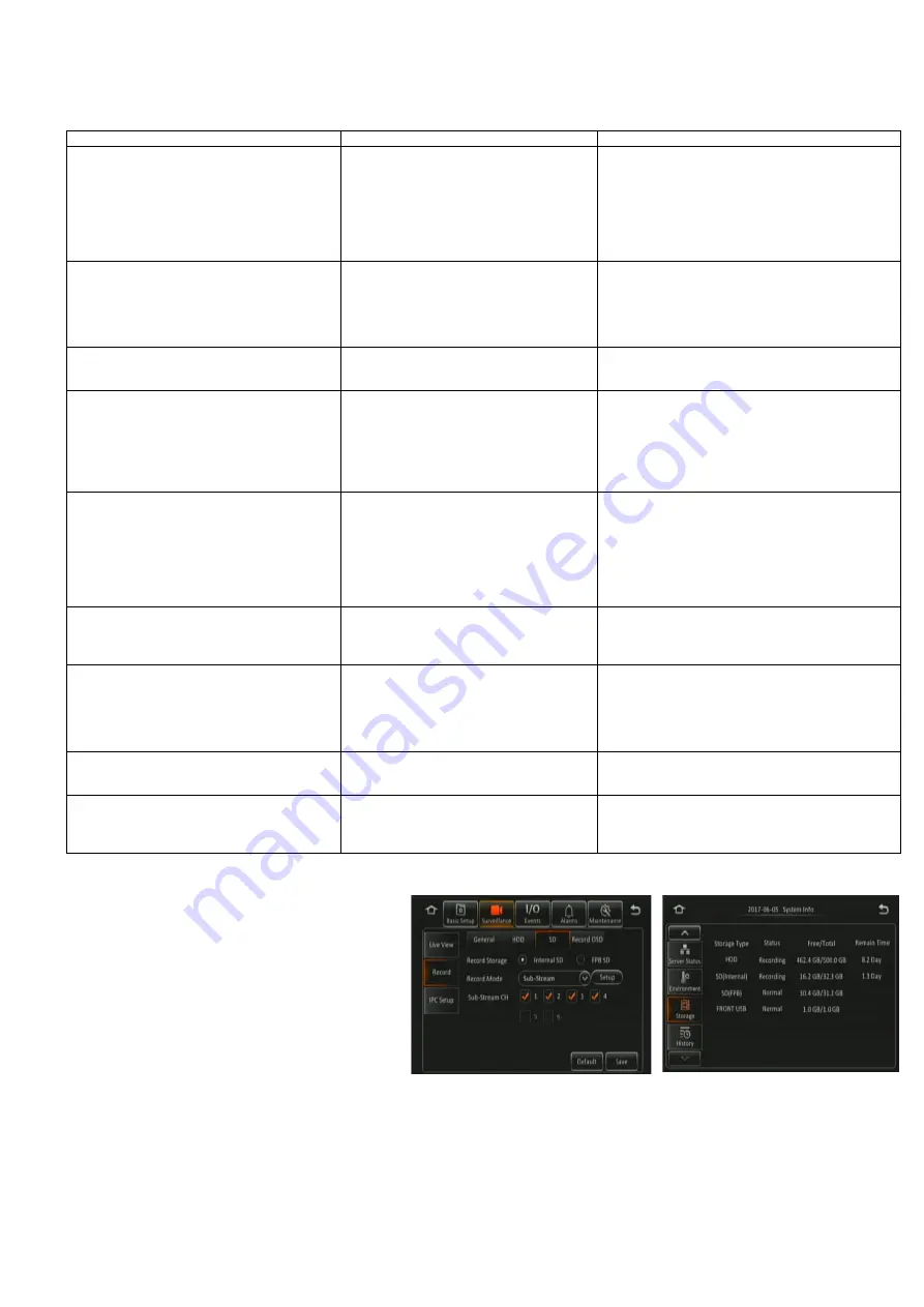
When you connect a Fireproof box to the MDR.
This needs to be enabled in the OSD. Go to
Surveillance > Record > SD > FPB SD.
•
The MDR may restart to engage this new
hardware device.
•
All new fireproof boxes must be formatted before
use.
•
Please follow the below steps to do this:
➢
Format as FAT32 first so the correct storage
capacity displays
➢
Then format as MDR5 so the MDR can
record to this storage
•
The process above will never have to be repeated
•
Finally confirm storage under system information,
it should show under SD(FPB) as 31.2GB.
FPB SD Enable Figure 251
FPB SD Storage Capacity Figure 252
Summary of Contents for MDR-504 Series
Page 100: ...100 ...
Page 101: ...101 ...
Page 102: ...24 08 2021 04 11 25 MDR 500 Series Installation Operation Guide v2 0 ENG 6326A docx ...


