background image


Wall mounting


To be used at the wall, the distribution box must be mounted to the wall using wall plugs and screws. 
The recommended mounting height is with the controls at eye level.


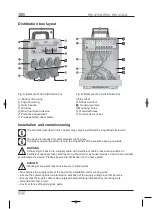
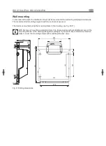
The device is mounted using the mounting holes in the housing, see fig. B (11).


With this type of mounting, protection class II no longer applies without additional cover of the 
mounting screws in the housing (dangerous voltage). If you would like to maintain protection 
class II, cover the mounting screws with suitable protective caps.


280


116


250


Fig. C: Drilling dimensions


250


WV 4/16A IP44 · WV 4/32A IP44


4x


Ø

5.5


2x


Ø

6


2x


Ø

10


27

.4


292


20

0


20

0


40


Summary of Contents for WV 4/16 A IP44

Page 1: ... warning marks a possibly dangerous situation Non compliance can lead to fatal or severe injuries DISPOSAL Mandatory self declaration according to the WEEE directive on the disposal of equipment Intended use The distribution box is used as an indoor or outdoor power distributor for wall mounting or as a mobile distributor This product is designed for professional use Installation and permanent con...

Page 2: ...f the installation and operating instruction to the operator user of the device Operation Use Safe use is only ensured if these instructions are fully observed Read these instructions thoroughly prior to installation commissioning or operation The distribution box is to be properly installed maintained and commissioned by qualified experts in compliance with the relevant laws regulations and stand...

Page 3: ...h the hinged lids of the sockets opening upwards WARNING Connecting the device to a supply cable with insufficient cable cross section and or an insufficient upstream fuse could result in a fire which may cause injuries or lead to an overload and damage the device Please observe the information on the name plate DANGER Working at live parts may cause severe or fatal injuries De energize the supply...

Page 4: ...the mounting holes in the housing see fig B 11 With this type of mounting protection class II no longer applies without additional cover of the mounting screws in the housing dangerous voltage If you would like to maintain protection class II cover the mounting screws with suitable protective caps 280 116 250 Fig C Drilling dimensions 250 WV 4 16A IP44 WV 4 32A IP44 4x Ø5 5 2x Ø6 2x Ø10 27 4 292 2...

Page 5: ... housing screws fig B 10 using a suitable tool Swivel the top of the housing fig A 2 downwards Position the device at the wall aligning the mounting holes Insert the mounting screws through the mounting holes fig B 11 of the bottom of the housing fig A 1 and tighten them Check that the device is secure Close the top of the housing Tighten the housing screws Check the connection of the sockets Supp...

Reviews: