Bräuniger GmbH
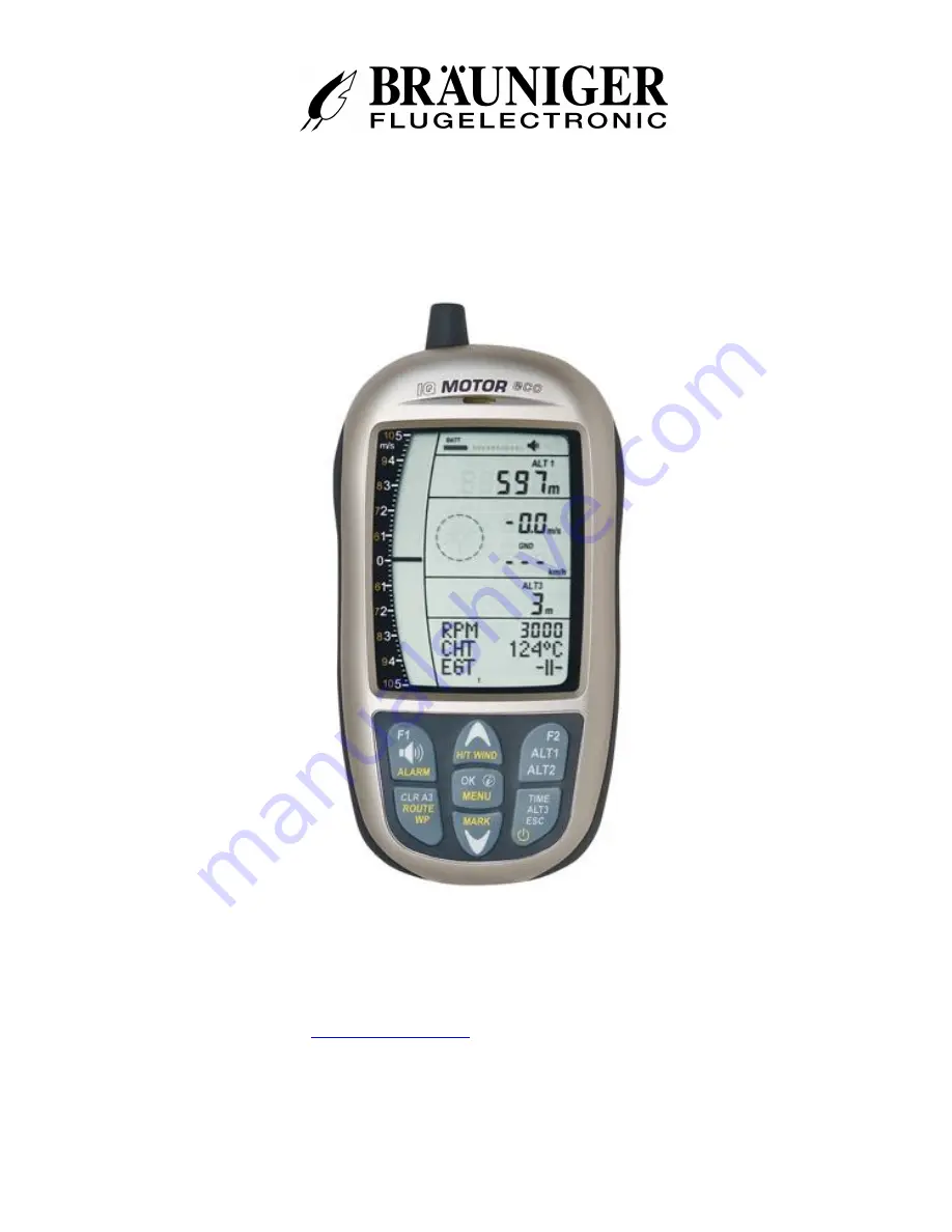
IQ-MOTOR
-eco
GPS
Operation manual
BRÄUNIGER
Flugelectronic GmbH
Dr.-Karl-Slevogt-Str.5 D-82362 Weilheim, Tel. +49 881 64750
[email protected]
www.brauniger.com
Firmware Vers.1.0X Revision: 22.07.2014
Page 1: ...iger GmbH IQ MOTOR eco GPS Operation manual BR UNIGER Flugelectronic GmbH Dr Karl Slevogt Str 5 D 82362 Weilheim Tel 49 881 64750 info brauniger com www brauniger com Firmware Vers 1 0X Revision 22 07...
Page 2: ...o 14 2 2 2 1 Average value Vario integrating Vario 14 2 2 3 Variometer Acoustics and volume level Sound 14 2 2 3 1 Audio level 14 2 2 4 Menu Settings Variometer 15 2 2 4 1 Digital Vario Integrator 15...
Page 3: ...Flight instrument settings 26 7 1 2 Waypoints and Routes 26 8 Transmitting new Software Firmware to the IQ BASIC GPS 27 9 Miscellaneous 27 10 Batteries 27 10 1 Batterie charge state 27 10 2 Battery r...
Page 4: ...al vario field 6 USB PC interface 7 Altimeter field ALT1 ALT2 8 Audio indicators 9 GPS satellite indicator 10 Loudspeaker port 11 Battery capacity 12 Flylink antenna Motor Box 13 Compass rose 14 Analo...
Page 5: ...flight recording For switch off the On Off key needs to be pressed until the question Switch off Press OK is prompted on the screen Again to prevent unintentional switch off also this action needs to...
Page 6: ...the menu submenus by use of the up down keys and to enter adjustments The main menu is quitted automatically at 30 seconds after the last entry Tip all instrument settings of the Main menu can be set...
Page 7: ...m the scale is automatically adapted The height scale is displayed on the right side 50 100m Variometer Graphics display In this graph page is illustrated the course of Variometer during the past 36 s...
Page 8: ...tor rotation speed 0 12000 rpm Cylinder temperature 20 800 C Motor temperature data display digital analog 4 Cylinder temperature 20 250 Exhaust gas temperature 20 800 Remark if no FlyLink connection...
Page 9: ...5 1 1 Keypad functions for text input editing After call up of Menu Pilot name Glider type or ID the 1st digit of the name is flashing By use of softkeys and the required character is selected there a...
Page 10: ...1400 Hz 16 Frequency Change Freq Change 0 1 2 3 4 16 Pitch Change Pitch Change 0 1 2 3 4 5 16 Pitch Mode Pitch Mode lin exp 16 Pre Thermal Threshold PThermThre sh 0 bis 1 0m s 16 Sink Acoustics Sink A...
Page 11: ...Q MOTOR eco GPS 11 dd mm ss Factory settings Pressure sensor zero point Press Offs 10 hPa Set instr to original condition Org Cond Original condition Device PCB No S N No Info SN No PCB No Sensor Adju...
Page 12: ...nt settings Units 2 1 1 1 Manual setting of altimeter Alt1 Set mode A1 of altimeter is called up by long pressure on the ALT1 key The possible settings are shown in the information field By brief pres...
Page 13: ...superelevation above landing site For this purpose ALT2 will be reset to zero related to the landing site altitude 2 1 2 2 Altimeter display Alt2 definition Altimeter A2 mode can be defined in the men...
Page 14: ...second and indicate the average value of climb or sink rate within the adjusted time span At gruff narrow hillside up wind this helpful readout may be used to determine if a circle or aft flight would...
Page 15: ...ec has defined 4 basic resp turbulence filters Variometer sensitivity response characteristics Filter No 0 weak filtering for very calm air in Winter 1 Default normal filtering for enjoyment thermal w...
Page 16: ...change The interrelation may be seen on graphic below Range 0 up to 4 factory setting 2 2 2 6 4 Variometer Climb acoustic Pitch change increase of tone interval per m s Main Setup Menu Variometer Acou...
Page 17: ...nly be set equally to the basic tone pitch for climb acoustics Sinktone threshold Main Setup Menu Variometer Acoustic Sinktone Threshold Application point As for climb acoustics the application point...
Page 18: ...measurements caused by inappropriate placing of the sensor inside lee position or of the blister in front of the body The wind vane sensor measures the true airspeed True Airspeed TAS With plugged wi...
Page 19: ...2 minutes are log recorded The flight time and all min max values are presented on the Info page short pressure on the key i Info After 20sec the previous display screen shall automatically reappear...
Page 20: ...re cases disturbances may in fact be very strong so that no safe signal transmission will be possible Sometimes the careful grounding of the ignition system to the motor housing will remedy We recomme...
Page 21: ...ected with RPM signal Remark if no connection to flight instrument is available the following notice is displayed on the flight instrument Battery Status LED flashing at the rhythm of Flylink LED Gree...
Page 22: ...r is monitored in regard to wire breakage The direction of mounting the sensor on the ignition wire does not matter 4 2 Cylinder head temperature sensor The temperature is captured by means of a therm...
Page 23: ...r scale The longer the bar the more precise the reception quality is As soon as the instrument has sufficient GPS satellite reception after energising min four the symbol GPS is shown All functions re...
Page 24: ...mat is selectable between 1 degrees minutes decimal places of minutes dd mm mmm factory setting 2 degrees minutes seconds dd mm ss 3 degrees decimal places of degrees dd ddddd Basically one should alw...
Page 25: ...t By brief pressure on the ESC key or after 30sec the instrument shall be switched off automatically Tip if during display of flight analysis page the OK key is actuated the device is not switched off...
Page 26: ...ble to the PC may only be plugged into the IQ MOTOR eco GPS while it is switched off The instrument shifts automatically to PC USB transmission mode Important at first the USB driver from Prolific inc...
Page 27: ...r recognise the interface Start the data transfer by clicking on Update Then the version of the instruments s Bootloader shall appear and the relevant bit rate The numbers appearing in the field on th...
Page 28: ...Cd Accumulators These batteries have significantly reduced capacity and they are less environment friendly Also the switching threshold is not laid out for NiCd Accum Remark the estimated operation ti...
Page 29: ...rature If temperature deviates from standard atmosphere the display of altitude calculated as per the international formula is no longer correct The altimeter displays during summer when temperatures...
Page 30: ...fact that receiving strength of the satellite signals is only approx 1 1000 of mobile radios these radio sets and other disruptive factors like notebooks should be operated as far away as possible fr...
Page 31: ...e judging committee would be aware of the manipulation Therefore the misuse is practically impossible The IGC file can be sent directly to the judging committee of the OLC via the Internet At present...
Page 32: ...eafter dry the instrument carefully by blowing warm air of max 60 C hair dryer Never place the instrument into a microwave stove Microwaves shall destroy the instrument immediately After complete dryi...
Page 33: ...ng to IGC format PC connection USB 1 1 Operating temperature 15 C to 50 C Holders for hang gliders and para gliders are available Technical data are subject to be altered without prior notification at...