


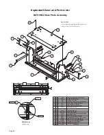


Page 14
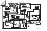
Unfold for:
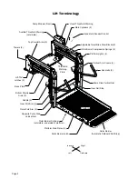
Lift Electrical
Schematic
Lift Wiring Diagram
33434A
NC
COM
NO
NC
COM
NO
RD(20) #1B
BU(20) #1B
BK(20) #1B
RD(20)
BU(20) #1A
BK(20) #1A
SOLID BUS
Platform Lights (Option)
Circuit Sentry
(
Circuit Breaker)
Bat.
Aux.
Lift
Power Cable
33688A
Pump Module
Power Feed
26082A-4
Connects to
Vehicle Battery
(+) Positive Post
Lead Wire
13362A
GN(20)
RD(10)
BK(20)
BK(20)
GN(20)
BK(20)
WH(18)
DK. BU(18)
BK(20)
or
Note polarity of diode. It
must be oriented as shown.
Detail at left shows two different
styles of diode identification.
GN(20)
GN(20)
GN(14)
GN(20)
RD/WH(18)
Ground
BU(20)
RD(22)
WH(18)
GN(18)
SILVER(22)
SILVER(22)
BK(22)
RD(20)
BK(20)
RD/WH(18)
SIL
VER(22)
GOLD(22)
GOLD(22)
SIL
VER(22)
Beeper
Threshold
Warning
Light
Outer Barrier
Raised Microswitch
Back
Plate
(Side view of
solenoids removed
from pump.)
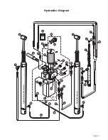
Hydraulic
Pump
B
A
T
A U X
GN(20)
GN(20)
GN(20)
GN(20)
BK(20)
BK(20)
BK(20)
GN(20)
GN(14)
OR(12)
OR(12)
33249RA
Threshold
Strip
Switches
IB Raised
Switch
IB Occupied
Microswitch
Counter
Interlock
Connection
Down
Fold Relief
Flasher
Outer
Barrier
Down
WH(20)
BN(20)
Outer Barrier
Fold Relief
Up
Microswitch
C-H
COM
NO
NC
Unfold
Microswitch
Power
Stud
GN(18)
BK(18)
WH(18)
BU(18)
RD(10)
VT(20)
VT(20)
RD(10)
RD(10)
OR(18)
33337A
VEHICLE SECURE 12V INPUT
2
RD(18)
RD(4)
RD(2)
RD(4)
N.O.
N.C.
C-H
COM
NO
NC
N.O.
N.C.
COM.
COM.
1
Partial Fold
Fuse
Microswitch
C-H
COM
NO
NC
Threshold / Alarm
Microswitch
BK(18)
WH(18)
RD(18)
RD(18)
GN(18)
BK(16)
BK(16)
RD(18)
31797A
GY/RD(18)
33231A
33255A
33659A
RD(18)
)
8
1(
D
R
RD(18)
BK(18)
DK. BU(18)
GN(20)
BK(18)
)
8
1(
K
B
4
5
A
3
3
0
1
3
9
9
A
3
3
0
1
3
)
8
1(
K
B
)
8
1(
K
B
)
8
1(
K
B
)
8
1(
K
B
)
8
1(
D
R
)
8
1(
K
B
RD(18)
BK(18)
RD(18)
BK(18)
BK(18)
BK(18)
4
GN(18)
GN(18)
BU(18)
WH(18)
WH(18)
GN(18)
N.O.
N.C.
.
M
O
C
C-H
COM
NO
NC
N.O.
N.C.
.
M
O
C
3
+ -
-
E
GN(20)
+
RD(20)
RD(20) #1B
OR(20)
BU(20)
BN(20)
VT(20)
WH(20)
BU(20)
BU(20) #1B
BU(20)
BK(20)
BU(20) #1A
BK(20)
BK(20) #1A
BK(20) #1B
FUSE HOLDER BK(16)
WHITE(18)
NOT USED
NOT USED
NOT USED
NOT USED
6
5
4
3
2
1
COLOR
NO.
9-COND WIRE CODE
GREEN(18)
NOT USED
NOT USED
9
8
7
VEHICLE 12V INPUT
LIFT NOT STOWED GROUND SIGNAL
NOT USED
NOT USED
NOT USED
NOT USED
6
5
4
3
2
1
COLOR
NO.
9-COND WIRE CODE
LIFT STOWED GROUND SIGNAL
NOT USED
NOT USED
9
8
7
1 2 3
4
5 6
7
8 9
2
1
1
2
1
2
2
1
1
2
2 1
1
2
2 1
Ground Detect
Microswitch
Bridging
Microswitch
BU(20)
BK(20)
1
2
NC
COM
NO
1
2
3
4
5
6
7
8
9
32519A & 31228
34294A
L
T
. BU / GN(18)
GN(10)
REDUNDANT
POWER
RELAY
OR
BU
Fold/Unfold
Switch
WH
BK
GN
RD
L
G
Up/Down
Switch
Switch Box
(As Viewed From Terminal
Side of Switch)
NOT USED
BLACK - 6 COND. (DOWN)
RED - 6 COND. (UNFOLD)
GREEN - 6 COND. (FOLD)
ORANGE - 6 COND. (UP)
BLUE - 6 COND. (-)
WHITE - 6 COND. (+)
6
5
4
3
2
1
COLOR
NO.
7-COND WIRE CODE
7
NOT USED
WHITE(18)
RED(18)
GREEN(18)
TAN/ORANGE(18)
GREEN(20)
BLACK(20) and BLACK(20)
6
5
4
3
2
1
COLOR
NO.
7-COND WIRE CODE
7
2 1
5 4 3
7 6
C-H
COM
NO
NC
Stow
Interlock
Microswitch
BU(18)
GN(18)
BK(18)
RD(18)
WH(18)
N.O.
N.C.
C-H
COM
NO
NC
N.O.
N.C.
COM.
COM.
33257A
1
2
1
2
1
2
3
1
2
1
2
1
2
Lift Power
Switch
Down
Outer
Barrier
Fold
Relief
Outer
Barrier
Down
1
2
3
Fuse
Fold
Relief
Up/Fold
Solenoid
+
-
87a
86
87
30
GN(20)
85
GN(20)
LIFT STOWED / NOT STOWED GROUND SIGNAL
(Located in cavity #5 or #9 - see chart above)
31798A
YL/LT. BU(18)
NOTES:
1) JUNCTIONS ONLY OCCUR AT
MARKED INTERSECTIONS.
1
3
4
5
6
7
2
1 2
3 4 5
6 7
1
3
4
5
6
7
2
WHITE(20)
ORANGE(20)
VIOLET(20)
BLACK(20)
BLUE(20)
BROWN(20)
6
5
4
3
2
1
COLOR
NO.
9-COND WIRE CODE
NOT USED
NOT USED
RED(20)
9
8
7
VIOLET(20)
BLACK(18)
WHITE(20)
BLACK(20)
BLUE(20)
BROWN(20)
6
5
4
3
2
1
COLOR
NO.
9-COND WIRE CODE
NOT USED
NOT USED
RED(18)
9
8
7
1 2 3
4
5 6
7
8 9
1
2
3
4
5
6
7
8
9
2
1
5
3
6
4
GREEN(18)
BLACK(20)
DK. BLUE(18)
RED(18)
4
WHITE(18)
5
NOT USED
6
3
2
1
COLOR
NO.
6-COND WIRE CODE
4
5
1
2
6
3
GREEN(18)
BLACK(18)
BLUE(18)
RED(18)
4
WHITE(18)
5
NOT USED
6
3
2
1
COLOR
NO.
6-COND WIRE CODE
Lift
Ready
LED
RD(18)
RD(18)
RD(18)
RD(18)
RD(18)
RD(18)
RD(18)
RD(18)
RD(18)
OR(12)
OR(12)
OR(12)
OR(12)
Light
Relay
85
87a
86
87
30
BK(18)
BK(18)
DK. BU(18)
RD(18)
RD(18)
+
-
WH(18)
BK(18)
FOLD
RELAY
85
87a
86
87
30
GN(18)
L
T
. BU/GN(18)
4
3
2
1
COLOR
NO.
4-COND WIRE CODE
NOT USED
RED(18)
WHITE(18)
BLACK(18)
3
4
1
2
4
3
2
1
COLOR
NO.
4-COND WIRE CODE
NOT USED
WHITE(18)
BLUE(18)
BLACK(18)
2
1
4
3
2
1
5
3
6
4
ORANGE(18)
WHITE(18)
RED(18)
BLUE(18)
4
GREEN(18)
5
BLACK(18)
6
3
2
1
COLOR
NO.
6-COND WIRE CODE
4
5
1
2
6
3
TAN/ORANGE(18)
WHITE(18)
RED(18)
DK. BLUE(18)
4
GREEN(18)
5
BLACK(18)
6
3
2
1
COLOR
NO.
6-COND WIRE CODE
OR(12)
)
4(
K
B
d
n
u
or
G
p
m
u
P
22166A
Fuse
SOLID BUS
87a
86
87
30
85
RD/WH(18)