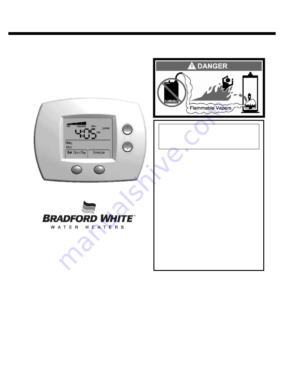
Bradford White 238-47808-00A Installation And Operation Manual Download Page 1


238-47808-00A 7/09 


SETBACK CONTROL 


INSTALLATION & OPERATION MANUAL 

With Troubleshooting Guide 


PLACE THESE INSTRUCTIONS ADJACENT TO WATER HEATER AND NOTIFY OWNER TO KEEP FOR FUTURE REFERENCE 

-


Do not store or use gasoline or other 
flammable vapors and liquids in the 
vicinity of the water heater or any 
other appliance. 


-

    What to do if you smell gas: 


Do not try to light any appliance. 


Do not touch any electrical switch; 
do not use any phone in your 
building. 


Immediately call your gas supplier 
from a neighbor phone.  Follow 
the gas supplier instructions. 


If you cannot reach your gas 
supplier, call the fire department. 


-


For your family comfort, safety and 
convenience, it is recommended this 
Setback Control be installed and 
serviced by a plumbing professional. 

This manual must be used in 
conjunction with the Installation and 
Operation Manual for the water heater. 

Ambler, PA 19002 

www.bradfordwhite.com 

Tech. Service.......................... (800) 334-3393 
Service Parts  ......................... (800) 538-2020 
Warranty Department  ............ (800) 531-2111 

Summary of Contents for 238-47808-00A

Page 1: ...ch any electrical switch do not use any phone in your building Immediately call your gas supplier from a neighbor phone Follow the gas supplier instructions If you cannot reach your gas supplier call...

Page 2: ...interface to furnace air conditioning thermostats Precision control of water temperature CONGRATULATIONS You have just purchased one of the finest water heater accessories on the market today This In...

Page 3: ...a qualified service technician Whenever the water heater is filled with cold water condensate will form on the cool tank surface and drops of water will fall on the hot burner and combustion chamber...

Page 4: ...r temperature during periods when hot water is required is 120 F 49 C During setback periods the recommended water temperature is 85 F 29 C If it is possible that hot water will be needed during the L...

Page 5: ...uttons 24 Display Key 25 Display Features 25 Reference Time Water Temperature Table 26 The Start up Procedure 27 Setting the Setback Control Schedule Initial Set up 31 Editing the Setback Schedule 40...

Page 6: ...on Box Assembly was already factory installed or installed as part of the Performance Package Unplug the Water Heater and Setback Control Step 1 Unplug the water heater and Setback Control This is sho...

Page 7: ...posite directions as shown in Figure 3 Retain the protective plate if the Setback Control will be remote mounted Figure 3 Install Batteries Step 4 Remove the battery holder from the Setback Control an...

Page 8: ...ontrol into the backplate connected to the Setback Control Junction Box Assembly as shown in Figure 5 Figure 5 Powering the Water Heater and Setback Control Step 6 Plug in the water heater and the tra...

Page 9: ...Unplug the water heater and Setback Control This is shown in Figure 7 Remove the Setback Control from the Backplate Step 2 Remove the Setback Control from the backplate attached to the Setback Contro...

Page 10: ...Figure 9 Mount the Protective Plate Step 4 Mount the Setback Control Protective Plate in a desired location Be sure that the Setback Control will not be direct sunlight as the display may be difficul...

Page 11: ...backplate on the Setback Control Junction Box Assembly to the Setback Control Protective Plate This is shown in Figure 11 Label the Wires for Remote Mounting Step 6 Label the 3 cut wires A B and C re...

Page 12: ...gure 13 Install Wire A Backplate Step 8 Using wire A insert one end into the top terminal location on the backplate located on the Setback Control Junction Box Assembly This is shown in Figure 14 Be s...

Page 13: ...Be sure that the wire already located in this location is not dislodged Fasten Wire A into its Designated Location Backplate Step 9 Tighten the slotted screw in the top terminal location on the backpl...

Page 14: ...n in Figure 17 Figure 17 Install Wire C Backplate Step 12 Using wire C insert one end into the bottom terminal location on the backplate located on the Setback Control Junction Box Assembly This is sh...

Page 15: ...he bottom terminal location on the backplate located on the Setback Control Junction Box Assembly This is shown in Figure 19 Figure 19 Route Wires to Protective Plate Step 14 Route all three wires to...

Page 16: ...location on the Protective Plate This is shown in Figure 20 Fasten Wire A into its Designated Location Protective Plate Step 16 Tighten the slotted screw in the top terminal location on the Protectiv...

Page 17: ...on on the Protective Plate This is shown in Figure 22 Figure 22 Fasten Wire B into its Designated Location Protective Plate Step 18 Tighten the slotted screw in the middle terminal location on the Pro...

Page 18: ...he Protective Plate This is shown in Figure 24 Figure 24 Fasten Wire C into its Designated Location Protective Plate Step 20 Tighten the slotted screw in the bottom terminal location on the Protective...

Page 19: ...the Protective Plate and press until it is fully seated This is shown in Figure 26 Figure 26 Install Cover Plate Step 22 Snap the Setback Cover Plate onto the backplate located on the Setback Control...

Page 20: ...ounting the Setback Control 20 Powering the Water Heater and Setback Control Step 23 Plug in the water heater and the transformer to power the Setback Control This is shown in Figure 28 Figure 28 Tran...

Page 21: ...water heater and Setback Control This is shown in Figure 29 Removal of Setback Control Junction Box Assembly Cover Step 2 Remove Setback Control Junction Box Assembly cover by unscrewing the two Phil...

Page 22: ...4 Replace the two batteries with 2 AAA batteries The batteries should be oriented as shown in Figure 32 Figure 32 Re installation of Battery Holder Step 5 Replace the battery holder with the new batt...

Page 23: ...back on the Setback Control Junction Box Assembly and reinstall the Philips head screws previously removed as shown in Figure 34 Figure 34 Powering the Water Heater and Setback Control Step 7 Plug in...

Page 24: ...ems will be shown The image below is an example of what the Setback Control displays while operating in the HOME screen UP Button DOWN Button RIGHT Button LEFT Button Right Button Functions Left Butto...

Page 25: ...ernately shown The current period water temperature setpoint will be shown for approximately five seconds followed by the current time for approximately five seconds If the Setback Control has been se...

Page 26: ...elow can be filled out with your schedule for future reference Water Temperature Start Time Water Temperature Start Time Water Temperature Start Time Water Temperature Start Time Monday Tuesday Wednes...

Page 27: ...the Setback Control is powered up This is shown in Figure 38 Revision Level Screen Step 2 After a few seconds the software revision level of the Setback Control is shown An example is shown in Figure...

Page 28: ...ton This is shown in Figure 41 Select the Correct Minute Step 5 Using the UP increase minute or DOWN decrease minute buttons adjust the minute until the correct minute is shown This process is shown i...

Page 29: ...r DOWN index AM PM buttons select AM PM See Figure 44 Lock in AM PM Step 8 Press the RIGHT Next button to proceed This is shown in Figure 45 Select the Day Step 9 Finally select the day A day will be...

Page 30: ...up Procedure 30 Figure 47 Finishing the Start up Procedure Step 10 Press the LEFT Done button as shown in Figure 47 This completes the Setback Control Start up Procedure You will now be taken to the H...

Page 31: ...RIGHT Schedule button as shown in Figure 48 Select the Day Step 2 Monday is flashing initially Press the RIGHT Next button to proceed to the Wake Period for Monday This is shown in Figure 49 When the...

Page 32: ...RIGHT Next button to lock in the Wake Period start time as shown in Figure 51 Figure 51 Select AM PM Step 5 Using the UP index AM PM or DOWN index AM PM buttons select AM PM as shown in Figure 52 Lock...

Page 33: ...eriod Water Temperature Step 8 Press the RIGHT Next button to lock in the Wake period water temperature as shown in Figure 55 Select the Leave Period Start Time Step 9 Press the UP increase time by 15...

Page 34: ...RIGHT Next button to set the Leave start time which is shown in Figure 57 Figure 57 Select AM PM Step 11 Next using the UP index AM PM or DOWN index AM PM buttons select AM PM as shown in Figure 58 Lo...

Page 35: ...is shown in Figure 60 Lock in Leave Period Water Temperature Step 14 Press the RIGHT Next button to lock in the Leave period water temperature as shown in Figure 61 Select the Return Period Start Time...

Page 36: ...Press the RIGHT Next button to set the Return period start time which is shown in Figure 63 Figure 63 Select AM PM Step 17 Next using the UP index AM PM or DOWN index AM PM buttons select AM PM as sho...

Page 37: ...is shown in Figure 66 Lock the Return Period Water Temperature Step 20 Press the RIGHT Next button to lock in the Return period water temperature as shown in Figure 67 Select the Sleep Period Start T...

Page 38: ...me Step 22 Press the RIGHT Next button to set the Sleep period start time which is shown in Figure 69 Select AM PM Step 23 Next using the UP index AM PM or DOWN index AM PM buttons select AM PM as sho...

Page 39: ...button as shown in Figure 73 Now the Sleep time period is set for Monday This completes the one day of the Setback schedule To set the schedule for the remaining days of the week repeat the procedures...

Page 40: ...iting the Schedule Mode Step 1 From the Home screen press the RIGHT Schedule button as shown in Figure 75 Select the Day to Edit Step 2 Monday is flashing initially Using the UP increase day or DOWN d...

Page 41: ...tons until the wanted time is shown This is shown in Figure 78 Figure 78 Lock in the Wake Period Start Time Step 5 Press the RIGHT Next button to lock the Wake period start time for the day selected a...

Page 42: ...Water Temperature Step 8 Using the UP increase water temperature or DOWN decrease water temperature buttons select the Wake period desired water temperature This is shown in Figure 82 Lock in the Wak...

Page 43: ...period start time The time increments in 15 minute intervals just as it did for the Wake period This is shown in Figure 84 Lock in the Leave Period Start Time Step 11 Press the RIGHT Next button to lo...

Page 44: ...ave Period Water Temperature Step 14 Using the UP increase water temperature or DOWN decrease water temperature buttons set the Leave period desired water temperature This is shown in Figure 88 Lock i...

Page 45: ...eriod becomes active The time increments in 15 minute intervals just as it did for the Wake period This is shown in Figure 90 Figure 90 Lock in the Return Period Start Time Step 17 Press the RIGHT Nex...

Page 46: ...d Water Temperature Step 20 Using the UP increase water temperature or DOWN decrease water temperature buttons select the Return period desired water temperature This is shown in Figure 94 Lock in Ret...

Page 47: ...time The time increments in 15 minute intervals just as it did for the previous periods This is shown in Figure 96 Lock in the Sleep Period Start Time Step 23 Press the RIGHT Next button to lock in th...

Page 48: ...r temperature buttons select the Sleep period desired water temperature This is shown in Figure 100 Lock in the Sleep Period Water Temperature Step 27 Press the RIGHT Next button as shown in Figure 10...

Page 49: ...49 Figure 102 Exiting the Edit Schedule Mode Step 28 When you are finished editing the Setback schedule press the LEFT Done button to exit the Schedule editing mode as shown in Figure 102 You will no...

Page 50: ...erature or DOWN decrease water temperature buttons until the new desired water temperature is shown This is shown in Figure 103 Display of Temporary Hold Water Temperature Step 2 A temporary hold will...

Page 51: ...e new desired water temperature is shown This is shown in Figure 106 Display of Permanent Hold Water Temperature Step 2 A permanent hold will maintain the water heater setpoint at the new setting inde...

Page 52: ...time changes for daylight savings Enter Clock Day Editing Mode Step 1 From the Home screen press the LEFT Set Clock Day button as shown in Figure 109 Select Correct Hour Step 2 Using the UP increase h...

Page 53: ...rease minute or DOWN decrease minute buttons adjust the minute until the correct one is shown This process is shown in Figure 112 Lock in Correct Minute Step 5 Press the RIGHT Next button to set the m...

Page 54: ...h is shown in Figure 115 Select Correct Day Step 8 Using the UP increase day or DOWN decrease day buttons select the correct day This process is shown in Figure 116 Lock in Correct Day Complete Editin...

Page 55: ...h Enter Sabbath Time Period Editing Step 1 From the Home screen press the RIGHT Schedule button as shown in Figure 118 Select the Day to Edit Step 2 Monday is the first day that is shown flashing init...

Page 56: ...by 15 minutes buttons until the wanted time is shown This is shown in Figure 121 Figure 121 Lock in Wake Period Start Time Step 5 Press the RIGHT Next button to lock in the Wake period start time as s...

Page 57: ...e Wake Period Water Temperature Step 8 Using the UP increase water temperature or DOWN decrease water temperature buttons select the Wake period desired water temperature This is shown in Figure 125 L...

Page 58: ...15 minute intervals just as it did for the Wake period This is shown in Figure 127 Figure 127 Lock in Leave Period Start Time Step 11 Press the RIGHT Next button to lock in the Leave period start time...

Page 59: ...dit Leave Period Water Temperature Step 14 Using the UP increase water temperature or DOWN decrease water temperature buttons select the Leave period desired water temperature This is shown in Figure...

Page 60: ...in 15 minute intervals just as it did for the Wake period This is shown in Figure 133 Figure 133 Lock in Return Period Start Time Step 17 Press the RIGHT Next button to lock in the Return period start...

Page 61: ...he UP increase water temperature or DOWN decrease water temperature buttons select the Return period desired water temperature This is shown in Figure 137 Lock in Return Period Water Temperature Step...

Page 62: ...ute intervals just as it did for the previous periods This is shown in Figure 139 Figure 139 Lock in Sleep Period Start Time Step 23 Press the RIGHT Next button to lock in the Sleep period start time...

Page 63: ...Period Water Temperature Step 26 Using the UP increase water temperature or DOWN decrease water temperature buttons select the Sleep period desired water temperature This is shown in Figure 143 Lock...

Page 64: ...5 Continuing with Sabbath Time Period Editing To edit the schedule for Saturday return to Step 2 on page 55 and follow the same procedure When you are finished changing the Setback schedule press the...

Page 65: ...x 32 Lower tank sensor out of specification x x x x 55 Damper failed to close stuck open x x 56 Damper failed to open stuck closed x x 57 False ground in pilot assembly detected Replace pilot assembl...

Page 66: ...Notes 66...

Page 67: ...Notes 67...

Page 68: ...641 1670 Parts Fax 215 641 2108 Technical Support 800 334 3393 Fax 269 795 1089 Warranty 800 531 2111 Fax 269 795 1089 International Telephone 215 641 9400 Telefax 215 641 9750 Mississauga ON Sales 86...

Reviews: