1
RELAIS VLS/400
Appareil comportant deux relais
indépendantes à deux contacts
inverseurs.
Il est utilisé pour la commutation de
signaux audio et vidéo ou d’autres
signaux de basse puissance.
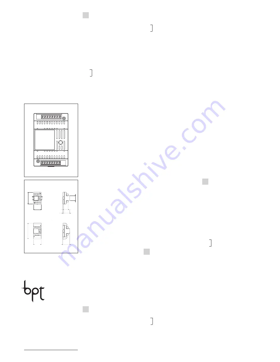
Fonction des bornes (fig. 1)
Bornier A (relais 1)
Bornier B (relais 2)
1
+
commande relais
2
–
3
contact 2 normalement ouvert
4
contact 1 normalement ouvert
5
contact 2 normalement fermé
6
contact 1 normalement fermé
7
commun 2
8
commun 1
Caractéristiques techniques
• Tension d’excitation: de 10 V à
18 Vcc.
• Consommation: 15 mA maxi
pour chaque relais.
• Pouvoir de coupure: 1 A 24 V.
• Température de fonctionnement:
de 0 °C à + 35 °C.
• Dimensions: module bas de 4
unités pour rail DIN (fig. 2).
L’appareil peut être installé sans
couvre-borniers dans des armoires
DIN avec rail EN 50022 (voir la fig
2 A) ou bien en saillie, avec le cou-
vre-borniers, en employant le rail
DIN fourni avec l’appareil (voir fig.
2 B).
VLS/400
I
ISTRUZIONI PER
L’INSTALLAZIONE
UNITA’ RELE’ VLS/400
Apparecchio costituito da due relé
indipendenti a due scambi.
Viene utilizzato per la commutazio-
ne di segnali audio e video o altri
segnali di bassa potenza.
Funzione dei morsetti (fig. 1)
Morsettiera A (relé 1)
Morsettiera B (relé 2)
1
+
comando relé
2
–
3
contatto 2 normalmente aperto
4
contatto 1 normalmente aperto
5
contatto 2 normalmente chiuso
6
contatto 1 normalmente chiuso
7
comune 2
8
comune 1
Caratteristiche tecniche
• Tensione di eccitazione: 10 ÷ 18
Vcc.
• Assorbimento: 15 mA max per
ogni relé.
• Potere di interruzione: 1 A, 24 V.
• Temperatura di funzionamento:
da 0 °C a + 35 °C.
• Dimensioni: modulo da 4 unità
basso per guida DIN (fig. 2).
L’apparecchio può essere installa-
to, senza coprimorsetti, in scatole
munite di guida DIN (EN 50022).
Per le dimensioni di ingombro
vedere la fig. 2 A.
Oppure può essere installato a
parete, con coprimorsetti, utilizzan-
do la guida DIN in dotazione.
Per le dimensioni di ingombro
vedere la fig. 2 B.
SMALTIMENTO
Assicurarsi che il materiale d’im-
ballaggio non venga disperso nel-
l’ambiente, ma smaltito seguendo
le norme vigenti nel paese di utiliz-
zo del prodotto.
Alla fine del ciclo di vita dell’appa-
recchio evitare che lo stesso
venga disperso nell’ambiente.
Lo smaltimento dell’apparecchia-
tura deve essere effettuato rispet-
tando le norme vigenti e privile-
giando il riciclaggio delle sue parti
costituenti.
Sui componenti, per cui è previsto
lo smaltimento con riciclaggio,
sono riportati il simbolo e la sigla
del materiale.
GB
INSTALLATION
INSTRUCTIONS
RELAY - MODULE VLS/400
VLS/400 consist of 2 separate
relays coils each with 2 switching
contacts.
It is used for the commutation of
audio and video or other low power
signals.
10.2007/2406-4600
Function of each terminal (fig. 1)
Terminal block A (relay 1)
Terminal block B (relay 2)
1
+
supply voltage to relay coil
2
–
3
normally open contact 2
4
normally open contact 1
5
normally closed contact 2
6
normally closed contact 1
7
common contact 2
8
common contact 1
Technical features
• Supply voltage: 10 ÷ 18 V DC for
each relay.
• Current demand: 15 mA max for
each relay.
• Max load to relay contact: 1 A at
24 V.
• Working temperature range: from
0 °C + 35 °C.
• Dimensions: 4 DIN units module,
low profile (fig.2).
The unit can be installed without
terminal covers into boxes provi-
ded with DIN rail (EN 50022).
Dimensions are shown in figure 2
A.
It can also be surface mounted,
using the DIN rail supplied, but fit-
ted with terminal covers.
Dimensions are shown in figure 2
B.
DISPOSAL
Do not litter the environment with
packing material: make sure it is
disposed of according to the regu-
lations in force in the country where
the product is used.
When the equipment reaches the
end of its life cycle, take measures
to ensure it is not discarded in the
environment.
The equipment must be disposed
of in compliance with the regula-
tions in force, recycling its compo-
nent parts wherever possible.
Components that qualify as recy-
clable waste feature the relevant
symbol and the material’s abbre-
viation.
D
INSTALLATIONS-
ANLEITUNG
RELAIS - EINHEIT VLS/400
VLS/400 besteht aus 2 separaten
Relais mit jeweils 2 Doppelkontak-
ten.
Wird zur Umschaltung des akusti-
schen und Video-Signals oder
anderer Signale mit niedriger
Leistung benutzt.
Belegung der Klemmleisten
(Abb.1)
Klemmleiste A (Relais 1)
Klemmleiste B (Relais 2)
1
+ Stromversorgung
2
– der Relaisspule
3
Normal geöffneter Kontakt 2
4
Normal geöffneter Kontakt 1
5
Normal geschlossener Kontakt 2
6
Normal geschlossener Kontakt 1
7
Gemeinsamer Kontakt 2
8
Gemeinsamer Kontakt 1
A
1
B
2 3 4 5 6 7 8
8 7 6 5 4 3 2 1
1
2
43,5
45
7,5
57
70
106
A
B
64,5
70
145
F
INSTRUCTIONS
POUR L’INSTALLATION
Technische Daten
• Stromversorgung der Relais-
spule: 10 ÷ 18 V DC.
• Stromaufnahme: max 15 mA für
jeder relais.
• Max. Belastung des Relaiskon-
takt: 1 A bei 24 V.
• Temperaturbereich: von 0 °C bis
+35 °C.
• Abmessungen: 4 DIN-Einheiten,
flach (Abb. 2).
Nach Entfernung der Klemm-
abdeckungen lassen sich diese
Geräte auf DIN-Montageschienen
in Verteilerkästen montieren (EN
50022).
Maßangaben, siehe Abb. 2 A.
Auch für Wandmontage geeignet.
Maßangaben, siehe Abb. 2 B.
ENTSORGUNG
Vergewissern Sie sich, dass das
Verpackungsmaterial gemäß den
Vorschriften des Bestimmungslan-
des ordungsgemäß und umwelt-
gerecht entsorgt wird.
Das nicht mehr benutzbare Gerät
ist umweltgerecht zu entsorgen.
Die Entsorgung hat den geltenden
Vorschriften zu entsprechen und
vorzugsweise das Recycling der
Geräteteile vorzusehen.
Die wiederverwertbaren Geräte-
teile sind mit einem Materialsym-
bol und –zeichen versehen.
BPT S.p.A.
Via Roma, 41
30020 Cinto Caomaggiore/VE/Italy
http: www.bpt.it/e-mail: [email protected]


