background image

English

LATITUDE is a trademark of

Boston Scienti

fi

 c Corporation or its af

fi

 liates.

Delta Mobile Systems is a trademark of Delta Mobile Systems.

GlobTek is a trademark of GlobTek, Inc.

MultiConnect is a trademark of Multi-Tech Systems, Inc. 

This manual contains instructions for the use of Models 6280 and 6290 
LATITUDE Communicators. These instructions are identical for both 
models. Technical differences, however, do exist between the models 
and are identi

fi

 ed where appropriate. The model number for your 

Communicator is located on its bottom label.

Summary of Contents for LATITUDE

Page 1: ...LATITUDE Communicator Comunicador LATITUDE PATIENT MANUAL MANUAL DEL PACIENTE ...

Page 2: ......

Page 3: ...English 1 Español 75 ...

Page 4: ......

Page 5: ...English LATITUDE Communicator ENGLISH ...

Page 6: ...lobTek Inc MultiConnect is a trademark of Multi Tech Systems Inc This manual contains instructions for the use of Models 6280 and 6290 LATITUDE Communicators These instructions are identical for both models Technical differences however do exist between the models and are identified where appropriate The model number for your Communicator is located on its bottom label ...

Page 7: ...tes 5 Buttons Connectors and Indicators 7 Installing Your Communicator 9 Confirming Switch Settings 9 Connecting Your Communicator 10 Software Download and Installation 10 Connecting to a Landline Telephone Jack 11 Connecting to the LATITUDE NXT USB Cellular Adapter 13 Where to Place Your USB Cellular Adapter 13 Normal Operation of the Communicator 16 Indicator Sequence When Using the Heart Button...

Page 8: ...LATITUDE System 45 Traveling with Your Communicator 46 Communicator Use of the Telephone System 47 Using the Telephone While the Communicator is Making a Call 48 DSL Internet Service 48 Care and Maintenance 49 Cleaning the Communicator and Accessories 50 Returning Replacing or Disposing of the Communicator or USB Cellular Adapter 51 Setting Switches for PBX or Dial out Numbers 52 Connecting the US...

Page 9: ...ite The LATITUDE system is not meant to assist with health emergencies If you are not feeling well call your health care provider or dial 911 The LATITUDE Communicator The LATITUDE Communicator is an in home monitoring system that uses a wireless communication system to communicate with your implanted device The Communicator does not provide continuous monitoring It automatically reads implanted d...

Page 10: ... in most homes The Communicator supports tone dialing over an analog line The Communicator may work on other telephone systems such as digital subscriber line DSL and voice over Internet Protocol VoIP if those systems provide an analog interface for connecting the Communicator Follow the instructions in this manual when using the Communicator Keep all of your Communicator information in a convenie...

Page 11: ...d blood pressure monitor The USB sensor adapter provides a wireless connection between these products and the Communicator See Connecting the USB Sensor Adapter on page 53 Clinician Website The clinician website provides authorized health care providers a convenient and secure way to obtain and analyze information from a patient s implanted device The LATITUDE system normally displays your device ...

Page 12: ...cheduled by your health care provider If the Heart button is flashing press it and then watch the indicators on the Communicator Call your health care provider if the Call Doctor icon Figure 2 on page 8 is lit When Not to Use Your Communicator The Communicator is designed to work only with your implanted device It will not work with another patient s implanted device The Communicator should be use...

Page 13: ...e you spend a considerable amount of time each day Where the Communicator and all its cables and accessories will be kept dry and not exposed to humidity or potential water contact Important Notes It is very important that the Communicator remains plugged into the electrical outlet Your Communicator should remain connected to a telephone line unless you are subscribed to the LATITUDE Cellular Data...

Page 14: ...ayers personal computers and other electronic equipment Electrical safety It is recommended that the customer install a surge protector between the electrical wall outlet and the Communicator This is to avoid damage to the Communicator caused by local lightning strikes and other electrical surges Electrical cable wall plugs and other accessories must be in good condition before use Boston Scientif...

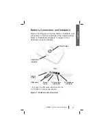
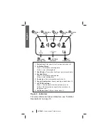
Page 15: ...s on the front and back of the Communicator Refer to Indicator Descriptions on page 19 for a description of each indicator Figure 1 Buttons and connectors To telephone wall jack To telephone optional Power input Status button USB ports to connect the USB sensor adapter and or the LATITUDE NXT USB Cellular Adapter Heart button LATITUDE indicator ...

Page 16: ...g data 5 Doctor Icon Data successfully sent when lit 6 Sensor Reading Icon Sensor reading received when lit 7 LATITUDE Indicator Green Communicator is active and ready to use Yellow Flashes yellow during start up process or to indicate an error 8 Call Doctor Icon Call your doctor when lit Figure 2 Indicators For more information about indicators see Indicator Descriptions on page 19 Heart Button S...

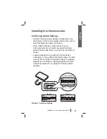
Page 17: ...he bottom of your Communicator do not match the switch settings shown below slide them up or down to set them as shown Landline telephone connection only Switches numbered 1 3 may differ from those shown if a dial out number or prefix is needed to place an outside telephone call Refer to Setting Switches for PBX or Dial out Numbers on page 52 for those switch settings Figure 3 6290 TM United State...

Page 18: ...vice and the Communicator Software Download and Installation Updated software may occasionally be pushed to your Communicator for download and installation If a software download is ready when installing the Communicator for the first time pressing the Heart button will trigger the download and installation process Wait for this process to complete which could take anywhere from a few minutes to m...

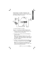
Page 19: ...lephone cord included into the jack labeled 2 Plug the other end of the cord into the telephone jack on the wall Note If you have DSL Internet service you may need to use a DSL filter between the telephone wall jack and the Communicator Refer to DSL Internet Service on page 48 3 Optional To use a telephone with this wall jack you may plug your telephone into the jack labeled Note Your Communicator...

Page 20: ...n firmly Check if the light on the AC adapter is on Important Your Communicator should remain connected to the electrical outlet and telephone wall jack 7 When installing the Communicator for the first time wait for the Heart button to flash with a white light Press the flashing Heart button to check if the Communicator can interrogate your implanted device and send your data to the LATITUDE syste...

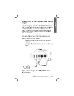
Page 21: ...llular adapter provided upon subscription to the Data Plan must be connected to the Communicator Refer to LATITUDE Cellular Data Plan on page 40 for more information Where to Place Your USB Cellular Adapter Place your USB cellular adapter Away from other electronic products or metal surfaces Alongside the Communicator and not under or on top of it Figure 5 Connecting to the LATITUDE NXT USB Cellul...

Page 22: ...wer is supplied the Communicator begins a startup process The power indicator on the top of the USB cellular adapter lights and remains lit except during a LATITUDE system reboot Note The wireless indicator will flash at various times and at various sequences This indicator is of no concern during normal operation The LATITUDE indicator flashes for up to one minute while the Communicator starts up...

Page 23: ...lashing Heart button to check if the Communicator can interrogate your implanted device and send your data to the LATITUDE system Continue with step 6 unless installation takes longer than 5 minutes or the Heart button flashes again In that case continue with Software Download and Installation on page 10 6 Determine whether the installation succeeded all indicators are lit a steady color or failed...

Page 24: ...terrogation or daily device check They will light when you use the Heart button as described in Interrogating Your Implanted Device on page 43 or when using the Status button as described in Checking that the Communicator Can Connect to the LATITUDE System on page 45 Note When color is used in this manual to explain operation of the Communicator an indicator shown as gray means that it is not lit ...

Page 25: ... interrogates your implanted device and then sends your data to the LATITUDE system More details about the colors and purpose of the indicators appear later in this manual The Communicator begins interrogating your implanted device after the Heart button is pressed The Patient icon lights blue The Collecting Waves light green in sequence and repeat while the Communicator interrogates your device ...

Page 26: ... was a success The Sending Waves light green in sequence and repeat while the Communicator places a call and starts sending your data to the LATITUDE system The Doctor icon lights blue showing the Communicator successfully sent your data to the LATITUDE system All the indicators shown stay lit for 2 minutes to show the entire process was a success ...

Page 27: ...stem Collecting a measurement from a prescribed weight scale or blood pressure monitor One or more indicators may light or flash a different color to indicate some type of action may need to be taken Refer to Troubleshooting Errors on page 26 Patient Icon Shows the Communicator is interrogating collecting data from your implanted device Lights blue when the Heart button is pressed and an interroga...

Page 28: ...anted device Light green for 2 minutes to indicate the interrogation was a success Heart Button Flashes with a white light if you need to complete a previously scheduled interrogation Lights a solid white for 2 minutes to indicate the interrogation is complete May also be used to manually initiate an interrogation of your implanted device Refer to Interrogating Your Implanted Device on page 43 bef...

Page 29: ...ITUDE system is in progress Light green for 2 minutes to indicate the connection to the LATITUDE system was a success and any collected device data was sent Doctor Icon Lights blue for 2 minutes to indicate the Communicator has successfully connected to the LATITUDE system The Communicator sends any data it has collected from your implanted device weight scale or blood pressure monitor ...

Page 30: ...lly received a weight or blood pressure measurement LATITUDE Indicator Shows the Communicator is connected to electrical power It also shows if the Communicator startup process is being performed or if the Communicator is ready to use Lights green to indicate the Communicator is connected to electrical power and is ready to use Flashes yellow during the startup process May flash yellow for a long ...

Page 31: ... in Troubleshooting Errors on page 26 A red light ranks higher than a yellow light If an error for each color occurs at the same time only the red light is displayed Flashes yellow briefly after the Communicator is plugged into AC power The light turns off after the Communicator completes the startup process If the startup process does not complete it remains lit solid yellow ...

Page 32: ...splay The status of the last interrogation The status of the last connection to the LATITUDE system The indicators will light for 2 minutes If the Call Doctor icon was blinking it will stop blinking and stay lit Press and hold for more than 3 seconds The Sending Waves light green in sequence and repeat while the Communicator connects to the LATITUDE system Note If you pressed the Heart button the ...

Page 33: ...Status button to check if the Communicator has been operating normally The above image shows that all the Collecting and Sending Waves are lit green confirming that the last interrogation and the last connection to the LATITUDE system were a success When all the waves are green no action is needed ...

Page 34: ...iption of the types of errors are shown in Figure 7 A description of each error is provided in this section along with suggested actions to resolve each error Yellow Collecting Waves Indicate errors collecting information from your implanted device Yellow Sending Waves Indicate errors sending information to the LATITUDE system Call Doctor Icon Call your doctor when lit LATITUDE Indicator Yellow li...

Page 35: ...d to electric power or it is not functioning Action If the LATITUDE indicator is not lit check that both ends of the AC adapter are plugged in firmly Check if the light on the AC adapter is on If the Communicator is plugged into electric power and the light on the AC adapter is on contact your health care provider ...

Page 36: ...TUDE indicator is yellow A potential problem with your implanted device was detected but the Communicator cannot send any information collected from your implanted device to the LATITUDE system The Call Doctor icon and LATITUDE indicator will stay lit until the problem is resolved Action Your immediate response is required Call your health care provider ...

Page 37: ...and the LATITUDE indicator is yellow Indicates one of the following errors Your Communicator is currently unable to monitor your implanted device Monitoring of your implanted device was suspended through the LATITUDE system The Call Doctor icon and LATITUDE indicator will stay lit until the problem is resolved Action Call your health care provider ...

Page 38: ...Icon Lit LATITUDE Indicator Not Lit Description The Call Doctor icon is lit yellow and the LATITUDE indicator is not lit This indicates your Communicator may not be working properly Action You may need a replacement Communicator Contact your health care provider ...

Page 39: ...ibed in the following Wave sections Wave indicators light for 60 minutes unless the error is resolved sooner After 60 minutes all Wave lights are turned off and the LATITUDE indicator is lit green even if the problem was not resolved Note In addition to the Wave indicators lighting yellow to indicate an error the LATITUDE indicator lights yellow at the same time ...

Page 40: ...s described in Where to Place Your Communicator on page 5 Face the Communicator Sit directly in front of the Communicator Make sure you are within 10 ft 3 m of the Communicator Move any wireless electronic products such as cordless or cellular phones or baby monitors that are within 3 ft 1 m of the Communicator To verify that troubleshooting was a success Press the Heart button to start another in...

Page 41: ...or Sit directly in front of the Communicator Make sure you are within 10 ft 3 m of the Communicator Remain still until the interrogation is complete Do not move away from the Communicator Move any wireless electronic products such as cordless or cellular phones or baby monitors that are within 3 ft 1 m of the Communicator To verify that troubleshooting was a success Press the Heart button to start...

Page 42: ...e to establish wireless communication with your implanted device due to interference from another person s implanted device Action If you are planning to interrogate your device wait 10 minutes Then try pressing the Heart button again to initiate the interrogation Do not press the Heart button while the interrogation is in progress unless you intend to stop the interrogation If you see three yello...

Page 43: ...o connect using the LATITUDE Cellular Data Plan Action If using a landline telephone connection Check that the telephone cord provided with the Communicator is plugged in tightly to a telephone wall jack and the Communicator Pick up the telephone and check for dial tone If no dial tone try a different telephone wall jack If you have DSL Internet service ensure you are using a DSL filter between th...

Page 44: ...ve the Communicator to another location that may have better cellular reception If other locations do not work after trying another connection try plugging the Communicator into an active telephone wall jack To verify that troubleshooting was a success Press and hold the Status button until the Sending Waves light green in sequence and repeat If the connection is successful all three Sending Waves...

Page 45: ...ne answering machine or computer may be using or attempting to use the telephone line Action If using a landline telephone connection Make sure your telephone is not being used at this time Pick up the telephone and check for dial tone If no dial tone try a different telephone wall jack Remove any splitters between the Communicator and the telephone wall jack If you have DSL Internet service ensur...

Page 46: ...ave not activated the LATITUDE Cellular Data Plan see page 40 Move the Communicator to another location that may provide a stronger cellular signal If other locations do not work after trying another connection try plugging the Communicator into an active telephone wall jack To verify that troubleshooting was a success Press and hold the Status button until the Sending Waves light green in sequenc...

Page 47: ...the bottom of the Communicator are set correctly for your country and whether you need to dial a number to get an outside line Refer to Confirming Switch Settings on page 9 Press and hold the Status button until the Sending Waves light green and show progress If you see three yellow waves after trying the above action your Communicator may not be set up correctly in the LATITUDE system Contact you...

Page 48: ...The LATITUDE Cellular Data Plan uses a data only network It does not send voice signals and it cannot be used with your cellular phone service Note Your Communicator is designed to use a landline telephone connection if it is plugged into an active telephone jack If connected your Communicator will send your device data over the landline telephone connection even if you are subscribed to the LATIT...

Page 49: ...n page 45 If you travel to another location with your Communicator check the connection from that location Troubleshooting and Support Subscription to the LATITUDE Cellular Data Plan does not guarantee coverage Actual coverage may be affected by such things as terrain weather foliage buildings and other construction signal strength customer equipment and other factors The Sending Waves may light y...

Page 50: ...scription will automatically be discontinued if you miss two or more payments You will need to discontinue your subscription if you stop using the LATITUDE system or if you want to return to using a landline telephone connection Make sure your health care provider is aware of any changes in service For information on returning replacing or disposing of your USB cellular adapter see page 51 ...

Page 51: ...interrogate your device after repeated attempts the Heart button will flash to allow you to complete the interrogation manually The Heart button also flashes the first time you use the Communicator The Heart button is designed to enable you to manually interrogate your implanted device Manual interrogation is a feature that must be enabled by your health care provider When you press the Heart butt...

Page 52: ...e has been re enabled CAUTIONS Normal use of the LATITUDE system has been accounted for in the projected battery life of your implanted device Using the Heart button more often than when the Heart button flashes or more often than instructed by your health care provider may lead to a decrease in the battery life of your implanted device If you feel unwell or are in need of urgent health care call ...

Page 53: ...the Status button on the back of the Communicator for more than 3 seconds The Sending Waves light green in sequence and repeat while the Communicator attempts to connect to the LATITUDE system If both Collecting and Sending Waves light you did not press the Status button long enough Pressing the Status button for less than 3 seconds displays the status of the last interrogation and the status of t...

Page 54: ... an extended period whether or not you take your Communicator Your health care provider may need to temporarily change your interrogation schedule or if you are traveling outside the country give you information about connecting to the LATITUDE system Note Model 6280 only Your Communicator is designed to be used only in the United States Canada Puerto Rico and Mexico Use of the Communicator in oth...

Page 55: ...face such as those commonly used in some businesses hotels and managed care facilities nursing homes skilled care facilities rehabilitation centers where telephones are typically provided by the facility If you have other telephone equipment including fax machine answering system or computer modem connected to the same phone line and the line is in use the Communicator will wait and attempt to pla...

Page 56: ...o reconnect later DSL Internet Service If you have digital subscriber line DSL Internet service provided through your telephone line you may need to install a DSL filter between the wall phone jack and the LATITUDE Communicator Most DSL filters are small rectangular devices with standard telephone jack connectors at each end These filters are typically provided by DSL service providers to connect ...

Page 57: ...r mishandle the Communicator or its accessories in a manner that would cause damage Avoid getting liquid on the unit other than cleaning it as recommended Do not use abrasive cloth or solvents to clean the unit Do not submerge the Communicator or its accessories in liquid Do not attempt to open the Communicator or any of its accessories Use this unit as described in this instruction manual Use onl...

Page 58: ...rniture could be affected as a result of continuous contact with rubber material such as the type used on the base of the Communicator CAUTIONS Do not use other cleaning fluids They may damage the front lens of the Communicator Never spray any cleaning fluid directly on the Communicator front lens Do not allow moisture to accumulate on or around the lens or Heart button Avoid using any cleaning fl...

Page 59: ...o return and replace it If you no longer need to use either your Communicator or USB cellular adapter United States Do not throw the Communicator or adapter in the trash Dispose of it at a local recycling site that accepts electronics Contact your local authorities to learn how to dispose of it Puerto Rico Canada or Mexico Do not dispose of the Communicator or adapter Contact your health care prov...

Page 60: ...s you to enter a dial out number or prefix to place an outside call The first three white switches 1 2 and 3 on the bottom of the Communicator must be set to match your dial out number If using the USB cellular adapter switches 1 3 do not matter Switch settings for different dial out numbers are shown in Figure 8 Refer to Confirming Switch Settings on page 9 for information on switches 4 8 Figure ...

Page 61: ...onnection between these products and the Communicator Refer to Figure 9 1 Remove the cap from the USB sensor adapter 2 Plug the USB sensor adapter into either of the USB ports labeled on the back of the Communicator Leave the USB sensor adapter plugged into the Communicator so the Communicator can receive measurements whenever you use your weight scale or blood pressure monitor Figure 9 USB sensor...

Page 62: ...k Model GTM41061 1512 7 0 part 350118 001 included Power Supply Input 100 240 VAC 0 6 A 50 60 Hz Maximum Output 15 W Supply Mains Isolation AC adapter plug Minimum Operational Loop Current 20 mA Protection Against Electric Shock Class II Expected Service Life Meets the useful life of the implanted device from 4 2 to 12 6 years Analog Dialing Mode Tone Operating Temperature 41 F to 104 F 5 C to 40 ...

Page 63: ...Water IP21 light rain proof Communicator Implanted Device Radio Model 6280 Receive Bandwidth 190 160 kHz Frequency Band 916 5 MHz Modulation Transmit Type ASK Amplitude Shift keying Effective Radiated Power 1 25 dBm 0 75 mW Communicator Implanted Device Radio Model 6290 Receive Bandwidth 300 kHz MICS MedRadio 402 405 MHz Modulation Transmit Type FSK Frequency Shift keying Effective Radiated Power ...

Page 64: ...entific Model 6454 included with LATITUDE weight scale and blood pressure monitor Operational Frequency 2400 0 to 2480 0 MHz Modulation Type Adaptive Frequency Hopping Effective Radiated Power 14 dBm 25 mW Operating Temperature 32 F to 158 F 0 C to 70 C Storage Temperature 4 F to 185 F 20 C to 85 C Relative Humidity 10 to 85 noncondensing ...

Page 65: ...0 TX 824 849 MHz RX 869 894 MHz Effective Radiated Power 22 93 dBm PCS 1900 TX 1850 1910 MHz RX 1930 1990 MHz Effective Radiated Power 26 42 dBm W CDMA 850 TX 824 849 MHz RX 869 894 MHz Effective Radiated Power 15 83 dBm W CDMA 1900 TX 1850 1910 MHz RX 1930 1990 MHz Effective Radiated Power 18 76 dBm ...

Page 66: ...p your Communicator and all accessories out of the reach of small children and pets Small parts may cause choking or serious injury if swallowed and attached cords may pose a strangulation hazard Consult a health care professional immediately if this occurs Do not insert any object other than a phone connector into the phone jacks on the back of the Communicator There can be voltage on the electri...

Page 67: ...Special International Committee on Radio Interference emission requirements This device complies with part 15 of the FCC Rules Operation is subject to the following two conditions 1 This device may not cause harmful interference and 2 this device must accept any interference received including interference that may cause undesired operation This equipment complies with Part 68 of the FCC rules and...

Page 68: ...ule under the Medical Device Radiocommunication Service in part 95 of the FCC Rules and must not cause harmful interference to stations operating in the 400 150 406 000 MHz band in the Meteorological Aids i e transmitters and receivers used to communicate weather data the Meteorological Satellite or the Earth Exploration Satellite Services and must accept interference that may be caused by such st...

Page 69: ...ssary modifications to maintain uninterrupted service If the Communicator causes harm to the telephone network the telephone company will notify you in advance that temporary discontinuance of service may be required But if advance notice isn t practical the telephone company will notify the customer as soon as possible Also you will be advised of your right to file a complaint with the FCC if you...

Page 70: ...nd digital interfaces signal inputs and signal outputs must be certified according to the respective IEC standards Anyone who connects additional equipment to the signal input parts or signal output parts may configure a medical system and is therefore responsible that the system complies with the requirements of clause 16 of IEC 60601 1 2005 If in doubt consult the technical service department or...

Page 71: ...601 1 2 is the ability to Communicate with your implanted device Identify alert conditions in your implanted device Receive measurements from optional health monitoring equipment Communicate implanted device data and alert conditions to the LATITUDE system Communicate measurements and alert conditions from optional health monitoring equipment to the LATITUDE system Receive configuration updates fr...

Page 72: ...64 LATITUDE Communicator Patient Manual English ...

Page 73: ...lectronic equipment RF emissions CISPR 11 Class B The LATITUDE Communicator is suitable for use in all establishments including domestic establishments and those directly connected to the public low voltage power supply network that supplies buildings used for domestic purposes Harmonic emissions IEC 61000 3 2 Class A Voltage fluctuations flicker emissions IEC 61000 3 3 Complies a The LATITUDE Com...

Page 74: ... air 8 kV contact 15 kV air The relative humidity should be at least 15 percent Electrical fast transient burst IEC 61000 4 4 2 kV for power supply lines 1 kV for input output lines 2 kV for power supply lines 1 kV for input output lines Mains power quality should be that of a typical commercial or hospital environment Surge IEC 61000 4 5 1 kV differential mode 2 kV common mode 1 kV differential m...

Page 75: ...icator be powered from an uninterruptible power supply or a battery 40 UT 60 dip in UT for 5 cycles 40 UT 60 dip in UT for 5 cycles 70 UT 30 dip in UT for 25 cycles 70 UT 30 dip in UT for 25 cycles 5 UT 95 dip in UT for 5 sec 5 UT 95 dip in UT for 5 sec Power frequency 50 60 Hz magnetic field IEC 61000 4 8 3 A m 30 A m Power frequency magnetic fields should be at levels characteristic of a typical...

Page 76: ...mended separation distance calculated from the equation applicable to the frequency of the transmitter Recommended separation distances Conducted RF IEC 61000 4 6 3 Vrms 150 kHz to 80 MHz 3 Vrms 10 Vrms in ISM and amateur radio bands between 150 kHz and 80 MHze d 1 7 P 150 kHz to 80 MHz where P is the maximum output power rating of the transmitter in watts W according to the transmitter manufactur...

Page 77: ...izing electromagnetic radiation a The LATITUDE Communicator is intended for use in the electromagnetic environment specified above The customer or the user of the LATITUDE Communicator should assure that it is used in such an environment b At 80 MHz and 1 GHz the higher frequency range applies c These guidelines may not apply in all situations Electromagnetic propagation is affected by absorption ...

Page 78: ...f the measured field strength in the location in which the LATITUDE Communicator is used exceeds the applicable RF compliance level above the LATITUDE Communicator should be observed to verify normal operation If abnormal performance is observed additional measures may be necessary such as reorienting or relocating the LATITUDE Communicator g Over the frequency range 150 kHz to 80 MHz field streng...

Page 79: ...ic environment in which radiated RF disturbances are controlled The customer or the user of the LATITUDE Communicator can help prevent electromagnetic interference by maintaining a minimum distance between portable and mobile RF communications equipment transmitters and the LATITUDE Communicator as recommended in Table 4 according to the maximum output power of the communications equipment b For t...

Page 80: ...oduct contains copyrighted software that is licensed under the GNU General Public License GPL Under the terms of the GPL as published by the Free Software Foundation you may obtain the complete corresponding source code from us for a period of three years after our shipment of this product ...

Page 81: ...tional AC DC adapter power input Direct current DC Universal serial bus USB connector Part number Serial number Reference number Non ionizing electromagnetic radiation IEC 60601 Class II medical equipment protection against electrical shock Manufacturer Date of manufacture Follow instructions for use Protection against ingress of water Light rain proof ...

Page 82: ...ies to distribution box Power indicator applies to USB cellular adapter Wireless indicator applies to USB cellular adapter Waste Electrical and Electronic Equipment WEEE symbol Indicates separate collection for electrical and electronic equipment i e do not throw this device in the trash Indicates this product has passed a comprehensive testing procedure and the production plant is regularly monit...

Page 83: ......
Page 84: ... 55112 5798 USA Telephone 651 582 4000 Medical Professionals 1 800 CARDIAC 227 3422 Patients and Families 1 866 484 3268 www bostonscientific com 2013 Boston Scientific Corporation or its affiliates All rights reserved 359081 001 ENES US 2013 07 359081 001 ...

Reviews: