background image

WASP™ NEST4 Smart Receiver and Gateway Operations Manual 

- 20 - 

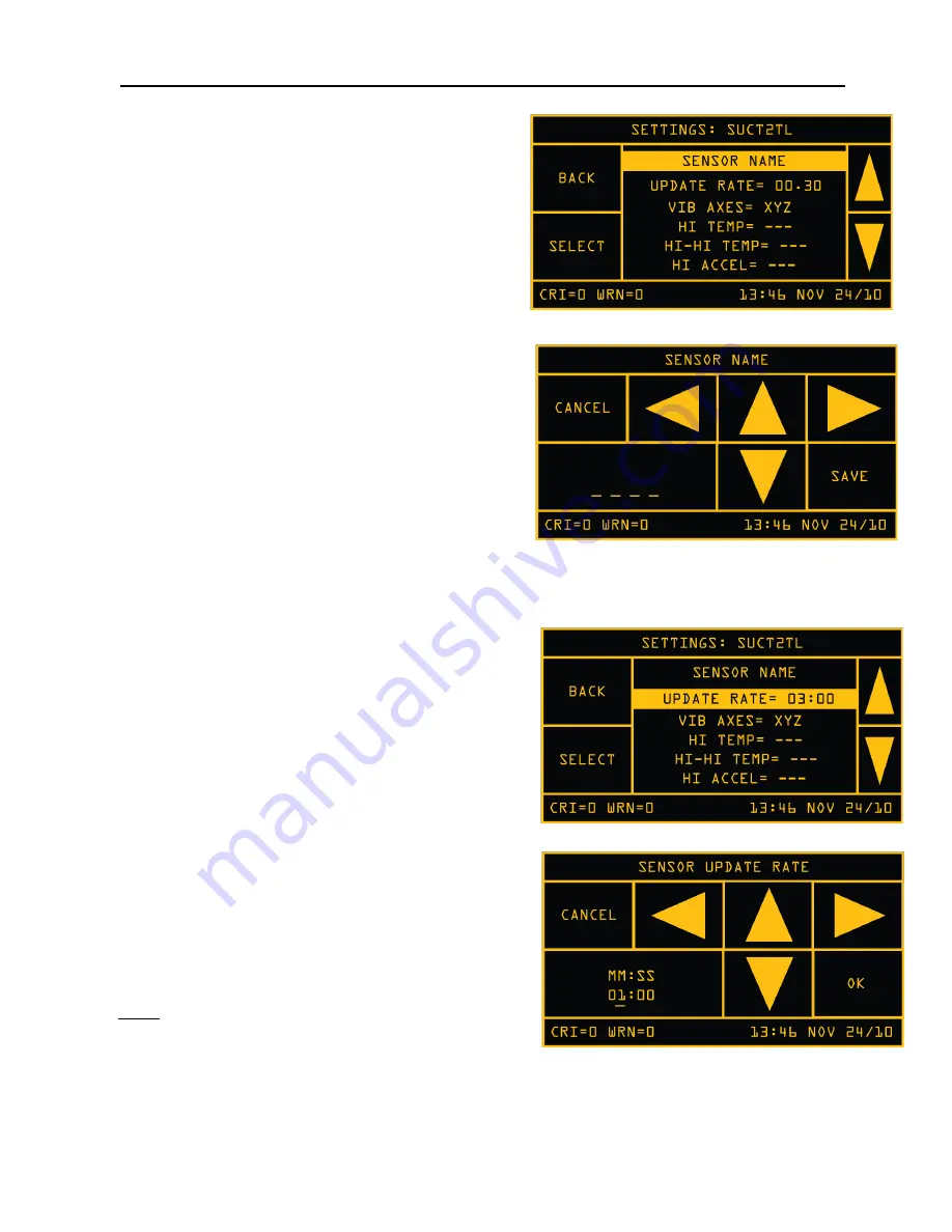
This SETTINGS screen allows the user to modify the 

sensor name, update rate, choose vibration axes, and 

configure the warning alarm and  critical alarm 

thresholds for the supported parameters. 
To set an individual parameter scroll the 

UP/DOWN


arrows to the desired setting, or by tapping either the 

top or bottom part of the screen. Press 

SELECT

 when 

the desired option is highlighted. 

3.2.7.1 Setting Sensor Name 

The sensors are identified by serial number and can 

be named to display a descriptive nomenclature of up 

to 7 characters. To name  a  sensor,  select the 

SENSOR NAME

  option from the SETUP menu  and 

use the 

UP / DOWN

  arrows  to  toggle through the 

numeric and alphabetic option for each character. The 

LEFT / RIGHT

 arrows will move the cursor to the next 

character position. Tap 

SAVE

 when completed. 

The new name will appear in the SENSOR STATUS 

windows. Serial numbers remain intact and visible in the SENSOR STATUS>DETAILS window. 

3.2.7.2 Setting Update Rate 

The update rate of each sensor can be individually set 

within a range of 3 seconds to 10 minutes. 

To modify the update rate, tap the 

SETUP

 section from 

the SENSOR STATUS screen. This takes you to the 

individual sensor SETTINGS screen. Scroll and 

highlight 

UPDATE RATE

 and tap 

SELECT. 


At the SENSOR UPDATE RATE menu use the arrow 

keys to move the cursor 

LEFT / RIGHT

 to the desired 

character position. Use the 

UP / DOWN

 arrows to add 

or subtract the minute or second numeric options. Tap 

OK

  to  complete  or 

CANCEL

  to return to settings 

screen. 

*Note:  The sensor will finish the current cycle, then 

complete one full cycle at the previous update rate prior 

to switching to the new update time. While the request 

is waiting to be sent, three dots (…) are shown instead of the update interval. 

Summary of Contents for WASP NEST4

Page 1: ...BossPac WASP NEST4 SMART RECEIVER AND GATEWAY USER MANUAL VERSION 1 0 ...

Page 2: ...SP is a PATENT PENDING technology owned by BossPac Engineering Technology BossPac Engineering Technology 1450 28 Street NE Bay 8 Calgary Alberta Canada T2A 7W6 Phone 403 216 1226 Fax 403 216 5557 E Mail info bosspac com Visit our website for more information www bosspac com ...

Page 3: ...VICE MISE EN GARDE LISEZ LE MANUEL AVANT UTILISATER WARNING TO PREVENT EQUIPMENT FAILURE AND OR DAMAGE AND OR PERSONAL INJURY REGULAR CALIBRATION AND INSPECTION OF THIS DEVICE IS REQUIRED MISE EN GARDE POUR PRЀVENIR LE DOMMAGE À L EQUIPMENT ET AU AUX PERSON LA CÀLIBRATION ET L INSPECTION REGULIER EST ŔEQUIS ...

Page 4: ...LITY FOR CLASS 1 DIVISION 2 AVERTISSEMENT RISQUE D EXPLOSION LA SUBSTITUTION DECOMPOSANTS RENDRE CE MATÉRIEL INACCEPTABLE POUR LES EMPLACEMENTS DE CLASSE 1 DIVISION 2 WARNING EXPLOSION HAZARD DO NOT RECONNECT POWER IN A HAZARDOUS ENVIRONMENT AVERTISSEMENT RISQUE D EXPLOSION NE PAS BRANCHEZ LA PRISE DANS UN ENVIRONMENT FLAMMABLE ...

Page 5: ...t Board 6 2 3 4 Circuit Board Terminal Block 6 3 Interface 7 3 1 System Status Screens 8 3 2 Main Menu 9 3 2 1 System Info 9 3 2 1 1 Version 9 3 2 1 2 Uptime 9 3 2 1 3 Radio 9 3 2 2 System Settings 10 3 2 2 1 SET LOG OPTION 10 3 2 2 2 Set Time Date 11 3 2 2 3 Set Password 11 3 2 2 4 Set Modbus Parameter 11 3 2 2 5 Set Temperature Unit 12 3 2 2 6 Set Velocity Units 13 3 2 2 7 Set Pressure Units 14 ...

Page 6: ...20 3 2 7 2 Setting Update Rate 20 3 2 7 3 Setting Sensor Vibration Axes 21 3 2 7 4 Setting Temperature Warning and Critical Alarm Thresholds 21 3 2 7 5 Setting Acceleration Warning and Critical Alarm Threshold 21 3 2 7 6 Setting Velocity Warning and Critical Alarm Thresholds 22 3 2 7 7 Setting Sensor Lost Warning 22 3 2 7 8 Setting Temperature Multiplier Factor 23 3 2 7 10 Temperature Calibration ...

Page 7: ...tallation The equipment should be installed by a professional or certified technician conversant with the certification requirements of the installation site 2 3 Wiring NEST Receiver 2 3 1 Nest Receiver Mounting The BossPac NEST receiver may be installed into existing panels or an enclosure mounted within 300 meters 1000 of the WASP s Ideal location would have direct line of sight to the sensors T...

Page 8: ...T FLAMMABLE 2 3 4 Wiring NEST Circuit Board The rear cover backplate needs to be removed to access the following connections USB and SD Card connections 2 3 5 Circuit Board Terminal Block The NEST circuit board has a 16 pin terminal block A diagram of the terminal block is shown below Pin 1 and Pin 2 are differential analogs inputs Pin 3 is a digital input Pin 4 is an analog output Pin 5 and Pin 7...

Page 9: ...isplayed in the bottom left of the interface These information sections top bar and bottom bar of the touch screen are not interactive and are only intended to provide current system statistics to the viewer NOTE Warnings indicate a sensor s has reached the warning limit pre determined in the Sensor Setup screen Critical Alarms indicate a sensor s has reached the pre determined shutdown limit and ...

Page 10: ...le through available status grid pages all other sensors Each individual sensor status screen will display the name of the sensor along with the current status Tapping on the bottom half of the screen will cycle the screen through more status data and settings of the sensor Tapping on the top half of the screen will cycle the screen through the available sensors For example Tap on right side of th...

Page 11: ...ECT 3 2 1 1 Version Selecting VERSION displays the current NEST firmware version The screen also displays the firmware compile date time as well as the revision number Tap BACK to return to the SYSTEM INFO screen or MAIN MENU to return to the MAIN MENU screen 3 2 1 2 Uptime The uptime screen simply displays how long the NEST has been active 3 2 1 3 Radio Selecting RADIO from the SYSTEM INFO screen...

Page 12: ...g data out direct option by choosing SET LOG OPTION from the SYSTEM SETTINGS menu MAIN MENU SYSTEM SETTINGS SET LOG OPTION Once in the LOG DATA OUT DIRECT screen simply choose SD CARD ONLY SD CARD USB STREAM or SD CARD RS485 STREAM and tap on SELECT SD CARD ONLY Logs data only to the SD Card SD CARD USB STREAM Logs data to the SD Card and streams data out the USB port This is intended for short te...

Page 13: ...ORD screen choose a 4 digit password by using the up down and right left arrows Click SAVE to save the new password 3 2 2 4 Set Modbus Parameter To configure MODBUS parameters select SET MODBUS PARAM from the SYSTEM SETTINGS selection screen A submenu will display the parameters to select RTU ADDRESS BAUD RATE or STOP BITS If the direct output option was enabled you would be asked to disable it be...

Page 14: ...ITS of the receiver to either 1 or 2 by using the arrows on the right of the screen and choosing SELECT 3 2 2 5 Set Temperature Unit You can set the units of temperature to either Celsius or Fahrenheit by selecting SET THERM UNITS from the SYSTEM SETTINGS menu Simply choose the unit of measurement and press SELECT MODBUS SET ADDRESS 21 C CRI 4 WRN 1 13 46 NOV 24 10 CANCEL BACK OK RTU ADDR 001 1 BI...

Page 15: ...ocity Units You can set the units of velocity to either mm s or IPS inch per second by selecting SET VEL UNITS from the SYSTEM SETTINGS menu Simply choose the unit of measurement and press SELECT MM S IPS VELOCITY UNITS 21 C CRI 4 WRN 1 13 46 NOV 24 10 CANCEL BACK SELECT MM S ...

Page 16: ... ALL SENSORS WILL REMOVE THE SENSORS AND ALL SETTINGS FROM THE NEST S MEMORY BE SURE THIS IS WHAT YOU INTEND TO DO BEFORE CLICKING OK MISE EN GARDE CLEAR ALL DЀGAGE LA LISTE DE CAPTEUR ET TOUT LEUR PARAMЀTRAGE SOYEZ SURE AVANT DE CLIQUER OK 3 2 2 10 Adjust Brightness The adjust brightness option allows you to change the brightness of the screen to improve the readability of the screen under differ...

Page 17: ...tion certification purposes IT IS NOT RECOMMENDED TO POWER THE DEVICE VIA THE USB PORT AS THE SUDDEN REMOVAL OF POWER MAY CORRUPT THE MICROSD CARD 3 2 3 2 Retrieving the Logs The microSD card will appear on the computer as a removable storage drive Navigate to the drive using the File Explorer Copy the logs of interest from the microSD card to a folder on your computers hard drive 3 2 3 3 Formatti...

Page 18: ...tem MAIN MENU NETWORK ADD DEVICE Enter a 6 digit numeric pass phrase and press START Using this pass phrase perform the Network Join procedure on the sensor to be added to the Network 3 2 4 2 Binding and Ignoring Sensor Pucks To bind a sensor to the receiver you will need to select a sensor from the FREE sensor list and bind it to the receiver To access the FREE SENSOR LIST MAIN MENU SENSOR LISTS ...

Page 19: ...FREE list screen after the confirmation allowing this process to be repeated Repeat this process until all the sensors you would like to bind are bound to the receiver If you happen to bind a sensor that you should not have go to SENSOR LISTS Then choose BOUND and scroll to find the sensor that should not have been bound Select the sensor then choose to IGNORE or REMOVE IGNORE places the sensor on...

Page 20: ...emoved from the NEST and all SENSOR LISTs will be cleared The NEST will automatically create a new network that devices can be connected to If you wish to have any devices previously connected to the NEST on the new network they will need to be added by following the procedure in Attaching a Device to The System 3 2 5 Alarm Overide The ALARM OVERIDE is used to ignore an alarm during the startup pr...

Page 21: ... example Tapping on the sensor square will take you to a status screen for this individual sensor To configure or modify the settings for this sensor tap the SETUP section bottom right from the SENSOR STATUS screen This will take you to the individual sensor SETTINGS screen SYSTEM STATUS 21 C CRI 4 WRN 1 13 46 NOV 24 10 SENSORS 24 CRIT 4 WARN 1 MAX TEMP 26 C MAX ACCEL 1 4 G MAX VEL 0 5 MM S MAIN M...

Page 22: ... cursor to the next character position Tap SAVE when completed The new name will appear in the SENSOR STATUS windows Serial numbers remain intact and visible in the SENSOR STATUS DETAILS window 3 2 7 2 Setting Update Rate The update rate of each sensor can be individually set within a range of 3 seconds to 10 minutes To modify the update rate tap the SETUP section from the SENSOR STATUS screen Thi...

Page 23: ... LO LO TEMP Press SELECT when the desired option is highlighted The bottom left quadrant of the screen will display the current setting in Celsius C or Fahrenheit F or DISABLED if there is no current threshold setting Select or modify the desired temperature by tapping the UP DOWN and LEFT RIGHT arrows Once the desired number temperature has been selected press OK to save or CANCEL the editing and...

Page 24: ...WN and LEFT RIGHT arrows Once the desired value has been selected press OK to save or CANCEL the editing and return to the SENSOR SETTINGS screen 3 2 7 7 Setting Sensor Lost Warning A warning can be issued to alert that a sensor has not reported to the NEST Receiver for a pre determined timeframe To set the amount of elapsed time a sensor can go without reporting scroll down to and highlight the L...

Page 25: ...o calibrate the sensor temperature reading to a reference reading Using the UP DOWN and LEFT RIGHT arrows enter the reference reading from an external device such as thermometer gun Tap on OK to save the calibration or tap on CANCEL to return to the settings screen Example If the WASP reads 23 C and the thermometer gun you are reading reads 26 C set the REF point to 26 C for that sensor This autom...

Page 26: ...on After several years of use the battery may need to be replaced Use a standard CR2032 Lithium Coin Cell In some models the battery is a component of the circuit board and replacement is not necessary WARNING DO NOT CONNECT OR DISCONNECT BATTERY UNLESS AREA IS KNOWN TO BE NON HAZARDOUS NE PAS BRANCHER OU DÉ BRANCHER LA BATTERIE DANS UN ENVIRONMENT FLAMMABLE 5 Contact Info BossPac engineers can be...

Page 27: ...erence that may cause undesired operation of the device Le présent appareil est conforme aux CNR d Industrie Canada applicables aux appareils radio exempts de licence L exploitation est autorisée aux deux conditions suivantes 1 l appareil ne doit pas produire de brouillage et 2 l utilisateur de l appareil doit accepter tout brouillage radioélectrique subi même si le brouillage est susceptible d en...

Reviews: