background image

10.4 

EX65 Explosion-Protected Camera


Maintenance | en 

43 

4.


Complete the back focus adjustments as described in section 10.5. Attach all of the 
connections at the back of the camera at the same connection points as when removed. 

5.


Reinstall the sliding tray back into the housing as shown in steps 9 - 12 of Configuration, 
page 24

Back Focus Adjustment 

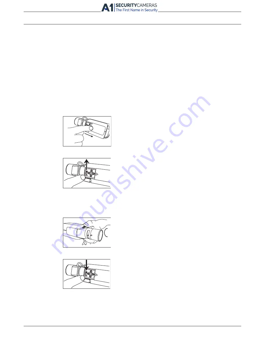
To optimize picture sharpness in both bright and low-level lighting, adjust the back focus. Use 
the camera's unique Lens Wizard. This ensures that the object of interest always remains in 
focus, even when focusing at the maximum lens iris opening (for example, at night).– When 
back focusing varifocal lenses, adjust to obtain a sharp picture in both wide-angle and tele 
positions for both far and near focus.– When back focusing zoom lenses, ensure that the 
object of interest remains in focus throughout the entire zoom range of the lens. To adjust 
back focus: 
1.


Open the side door panel at the side of the camera. 

B o

sch

2.  Unlock the back focus locking button. 

Bosch

3.


Press and hold the center key for more than two (2) seconds until the Install menu 
appears. 

4.


Select Lens Wizard and move the cursor to the Set Back Focus Now option. 

5.


Turn the back focus adjustment as necessary. 

Bosch

6.  Lock the back focus locking button. 

Bosch

7.


Press and hold the center key for more than two (2) seconds until all menus disappear. 

8.


Close the side door panel. 

Replacement of the Mounting Cradle 

1.


Disconnect power from the unit and, optionally, remove all connections. 

Bosch Security Systems, Inc.


Installation Manual 

2016.03 | 1.0 | F.01U.318.222 

                 Available from A1 Security Cameras 

    www.a1securitycameras.com email: [email protected]

10.5 

Summary of Contents for VEN-650 Series

Page 1: ...EX65 Explosion Protected Camera VEN 650 Series en Installation Manual Available from A1 Security Cameras www a1securitycameras com email sales a1securitycameras com ...

Page 2: ...Available from A1 Security Cameras www a1securitycameras com email sales a1securitycameras com ...

Page 3: ...ions 20 5 1 Power Cable Requirements 20 5 1 1 Wire Distance Guide 20 5 2 Coax Cable Requirements 20 5 3 Alarm Cable Requirements 21 5 4 Fiber Optic Cable Requirements 21 5 5 Making the Connections 21 6 Configuration 24 7 Mounting 26 7 1 Mounting the Unit 26 7 2 Installing the Sunshield 28 8 Operation 29 8 1 Menus 29 8 1 1 Top level menus 29 8 1 2 Menu navigation keys 30 8 2 Pre defined modes 30 8 ...

Page 4: ...menu 39 8 5 9 Defaults submenu 40 9 Troubleshooting 41 9 1 Customer Service 41 9 2 Camera Operation 41 10 Maintenance 42 10 1 Repairs 42 10 2 Removal of the Camera and Lens 42 10 3 Installation of the Camera and Lens 42 10 4 Back Focus Adjustment 43 10 5 Replacement of the Mounting Cradle 43 11 Technical data 45 2016 03 1 0 F 01U 318 222 Installation Manual Bosch Security Systems Inc Available fro...

Page 5: ...egistered trademarks and must be treated accordingly 1 3 Safety Precautions In this manual the following symbols and notations are used to draw attention to special situations Danger High risk This symbol indicates an imminently hazardous situation such as Dangerous Voltage inside the product If not avoided this will result in an electrical shock serious bodily injury or death Warning Medium risk ...

Page 6: ...Alarm Standard CCTV for Security Applications To meet the requirements of the EN50130 4 Alarm Standard an ancillary uninterruptable power UPS supply is necessary The UPS must have a Transfer Time between 2 6 ms and a Backup Runtime of greater than 5 seconds for the power level as specified on the product datasheet Adjustment of controls Adjust only those controls specified in the operating instruc...

Page 7: ...ecautions such as grounding for any outdoor device connected to this unit U S A models only Section 810 of the National Electrical Code ANSI NFPA No 70 provides information regarding proper grounding of the mount and supporting structure grounding of the coax to a discharge unit size of grounding conductors location of discharge unit connection to grounding electrodes and requirements for the grou...

Page 8: ...cting system ground to safety ground unless it is explicitly required However if the system ground and safety ground are connected and grounding loops are causing interference in the video signal use an isolation transformer available separately from Bosch Caution Connecting System ground to Safety ground may result in ground loops that can disrupt the CCTV system Notice Video loss is inherent to ...

Page 9: ...ions could void the user s authority to operate the equipment If necessary the user should consult the dealer or an experienced radio television technician for corrective action The user may find the following booklet prepared by the Federal Communications Commission helpful How to Identify and Resolve Radio TV Interference Problems This booklet is available from the U S Government Printing Office...

Page 10: ... db IIB T6 Gb Ex tb IIIC T85 C Db Relevant standards associated with the ATEX and IECEx certifications EN 60079 0 2012 A11 2013 EN 60079 1 2014 EN 60079 31 2014 IEC 60079 0 2011 Edition 6 IEC 60079 1 2014 Edition 7 IEC 60079 31 2013 Edition 2 2016 03 1 0 F 01U 318 222 Installation Manual Bosch Security Systems Inc Available from A1 Security Cameras www a1securitycameras com email sales a1securityc...

Page 11: ... 7 minimum 18 5 mm Supply Opening Blanking Element to Junction Box four openings provided 3 4 14 NPT N A 5 N A Housing to Front Cover M 103 2 mm 8 minimum 19 5 mm Warning To reduce the risk of ignition of hazardous atmospheres conduit runs must have a sealing fitting connected to the wall of the enclosure Warning DO NOT OPEN WHEN AN EXPLOSIVE ATMOSPHERE MAY BE PRESENT Bosch Security Systems Inc In...

Page 12: ... to be defective Such inspection may be on Buyer s premises and or BOSCH Security Systems may request the return of the Product at Buyer s expense However BOSCH Security Systems shall not be responsible for packing inspection or labor costs in connection with the return of Product No Product shall be accepted for warranty service that is not accompanied by a Return Authorization issued by BOSCH Th...

Page 13: ...lephone 585 421 4220 Fax 585 223 9180 or 717 735 6561 Email security repair us bosch com Canada Telephone 514 738 2434 Fax 514 738 8480 Europe Middle East Africa Region Please contact your local distributor or Bosch sales office Use this link http www boschsecurity com startpage html europe htm Asia Pacific Region Please contact your local distributor or Bosch sales office Use this link http www b...

Page 14: ...iber optic module that provides versatility for longer cable runs where electromagnetic interference is a concern 2 1 Unpacking This equipment should be unpacked and handled with care Check the exterior of the packaging for visible damage If an item appears to have been damaged in shipment notify the shipper immediately Verify that all the parts listed in the Parts List below are included If any i...

Page 15: ...x key 1 Multi use tool 1 Instruction Manual User supplied Parts Quantity Item 3 M6 x 1 0 x 16 mm bolts with lock washers 1 Bottle of Jet Lube NCS 30 grease as needed 1 Tube of Molykote BG 20 grease as needed 1 Tube of LA CO Slic Tite Paste with PTFE as needed Bosch Security Systems Inc Installation Manual 2016 03 1 0 F 01U 318 222 Available from A1 Security Cameras www a1securitycameras com email ...

Page 16: ...on and guidelines to help plan your installation Dimensional Drawings 135 5 30 128 5 04 102 4 01 116 4 57 125 4 93 Figure 3 1 Front View Ø 6 6 0 26 71 60 0 2 36 3 4 in NPT x4 Figure 3 2 Bottom view 2016 03 1 0 F 01U 318 222 Installation Manual Bosch Security Systems Inc Available from A1 Security Cameras www a1securitycameras com email sales a1securitycameras com ...

Page 17: ...ected Certifications page 9 All units have been tested prior to shipment It is advisable to check the unit s operation before installation Caution It is recommended that the installer wear an ESD strap or discharge any static electricity to ground before handling any electronic components Notice To avoid excessive moisture saturation inside the housing limit the amount of time that the unit housin...

Page 18: ...with a conduit seal or a gland and cable rated for the intended environment Use LA CO Slic Tite Paste with PTFE thread sealant on all conduit or gland threads Carefully follow all manufacturers instructions for applying grease and paste products All cable entry devices shall be ATEX IECEx certified for Ex d IIB T6 Gb and Ex tb IIIC T85 C Db IP67 rated at least 85 C 185 F suitable for the condition...

Page 19: ...tion Overview en 19 Note This product is serialized to ensure traceability Bosch Security Systems Inc Installation Manual 2016 03 1 0 F 01U 318 222 Available from A1 Security Cameras www a1securitycameras com email sales a1securitycameras com ...

Page 20: ...s the maximum wire distances for 14 16 and 18 AWG wires connected to a 24 VAC camera Watts 14 AWG 2 5 mm 16 AWG 1 5 mm 18 AWG 1 0 mm All Models 20 289 m 949 ft 182 m 597 ft 114 m 376 ft Coax Cable Requirements Cable type RG 59 U for runs 300 m 1000 ft RG 11 U for runs 600 m 2000 ft Cable size Outside diameter between 4 6 mm to 7 9 mm 0 181 in to 0 312 in Cable shape Round Shield 93 braided copper ...

Page 21: ...deo Bandwidth 5 Hz to 10 MHz Wavelength 850 nm Requirement Bosch LTC 4629 Fiber Receiver at controller end of system Terminal Connector ST Making the Connections All required connections are accessible by removing the rear end cap Notice Take care not to drop the end caps to prevent damage to the cap threads Notice Ensure that all wiring cabling has enough slack inside the housing so that you can ...

Page 22: ...ng the supplied hex key Loosen the rear end cap using the multi use tool To prevent damage to the o ring for every half turn counterclockwise turn back one quarter turn clockwise Note To prevent damage to the cap threads take care not to drop the end caps Figure 5 2 Removal of end cap with multi use tool 2 Unscrew the rear end cap by hand Set the cap aside 3 Feed power alarm if used and coaxial ca...

Page 23: ... Clean and grease the O ring and threads before replacing the end cap Refer to Installation Overview page 18 10 Replace the end cap 11 Tighten the end cap using the multi use tool Ensure that the O ring is properly seated After tightening ensure that there is no gap between the cap and the body of the housing 12 Tighten the set screws on the end cap using the supplied hex key Set screws must not p...

Page 24: ... to Operation page 29 for more information Note You may need to remove the sunshield to remove the front end cap more easily 1 Loosen the set screw on the front end cap using the supplied hex key 2 Loosen the front end cap using the supplied multi use tool To prevent damage to the o ring for every half turn counterclockwise turn back one quarter turn clockwise 3 Unscrew the front end cap by hand 4...

Page 25: ...efer to Operation page 29 10 Slide the inner mounting bracket assembly back into the camera housing and ensure that it locks into place at the back of the housing The bracket should not rotate and the camera should be completely level 11 Using a 10 mm wrench tighten the three 3 bolts to secure the inner mounting bracket assembly 9 Clean and grease the O ring and threads before replacing the end ca...

Page 26: ...onto one of a variety of mounting brackets originally designed for the MIC series of cameras Installers secure the adapter to a MIC Wall Mount Bracket MIC WMB and then secure the mounting cradle of the device to the mount adapter The MIC WMB can be mounted to any of the following MIC mounting brackets MIC Spreader Plate MIC SPR for installation on a wall MIC Corner Mount Bracket MIC CMB for instal...

Page 27: ... EX65 device to EXS ADPT 1 to MIC Wall Mount Bracket MIC WMB 2 Figure 7 2 EXS ADPT Mount Bolt Hole Pattern Bosch Security Systems Inc Installation Manual 2016 03 1 0 F 01U 318 222 Available from A1 Security Cameras www a1securitycameras com email sales a1securitycameras com ...

Page 28: ...5 Slightly loosen the six M6 bolts on both sides of the mounting cradle using a 10mm wrench or the multi use tool and make directional adjustments to the device so that it is pointing at the desired surveillance target See the following figure 6 Tighten all mounting bolts to 4 1 to 6 8 N m 3 to 5 ft lb 7 Connect wiring as explained in Connections page 20 and follow all local regulations and laws r...

Page 29: ...ancement functions The Install menu allows you to set the installation settings To access the menus follow the steps below 1 Open the side door panel at the side of the camera Bosch 2 Unlock the back focus locking button Bosch 3 Locate the five navigation keys behind the side door panel Figure 8 1 Advanced camera setup keypad Key Description 1 Up key 2 Right key 3 Down key 4 Left key 5 Menu Select...

Page 30: ...ized to capture details in high contrast and extremely bright dark conditions 5 Low noise Enhancements are set to reduce picture noise Useful for conditional refresh DVR and IP storage systems because reducing noise reduces the amount of storage required 6 Analog systems Use this mode if the camera is connected to a purely analog system for example matrix switcher with VCR or to a CRT monitor Usef...

Page 31: ...the ALC will operate A positive value is more useful for low light conditions a negative value is more useful for very bright conditions Some ALC adjustment may improve scene content when Smart BLC is enabled Peak average 15 to 15 Adjusts the balance between peak and average video control A negative value gives more priority to average light levels a positive value gives more priority to peak ligh...

Page 32: ... optimum shutter speed during set up Gain control On Fixed On the camera automatically sets the gain to the lowest possible value needed to maintain a good picture Fixed sets Fixed AGC value Maximum AGC or Fixed AGC 0 to 30 dB Selects the maximum value the gain can have during AGC operation Selects the gain setting for Fixed gain operation 0 is no gain Actual AGC Displays the actual AGC value from...

Page 33: ...Color the camera gives a color image as long as the light level permits Motion the camera avoids motion blur as long as the light level permits it switches to monochrome earlier than it would with Color priority IR contrast Enhanced Normal Enhanced the camera optimizes contrast in applications with high IR illumination levels Select this mode for IR 730 to 940 nm light sources and for scenes with ...

Page 34: ...darker A high positive value makes the level lighter and may bring out more detail in the darker areas Sharpness 15 to 15 Adjusts the sharpness of the picture 0 corresponds to the default position A low negative value makes the picture less sharp Increasing sharpness brings out more detail Extra sharpness can enhance the details of license plates facial features and the edges of certain surfaces D...

Page 35: ...olor saturation 15 gives a monochrome image EXIT Returns to main menu 8 4 7 VMD submenu Item Selection Description VMD Off Silent OSD Off Video Motion Detection VMD is off Silent video motion generates silent alarm OSD video motion generates on screen text message alarm VMD area Submenu Select to enter the area set up menu to define the detection area Motion indicator Indicates the peak of measure...

Page 36: ...as the false positive alarms may be considered a nuisance 8 5 Install menu structure Item Selection Description Language Submenu Select on screen display OSD language Lens Wizard Submenu Select to optimize the camera lens combination backfocus point Synchronization Submenu Sets synchronization parameters Alarm I O Submenu Program the alarm input and output functionality Connections Submenu Connect...

Page 37: ...dicator see below EXIT Returns to Install menu Synchronization submenu Item Selection Description Synchronization Internal Line lock HV lock Genlock Internal for free running camera operation Line lock to lock to the AC power supply HV lock locks the camera to the sync signal supplied to the SYNC connector Genlock locks the camera s subcarrier to the signal supplied to the SYNC connector Horizonta...

Page 38: ...ter On Off Switches notch filter on or off The notch filter can remove a Moiré pattern or color artifacts caused by closely spaced vertical lines or objects e g vertical security bars over windows Bilinx Comms On Off If Off Bilinx communications is disabled Camera buttons Enable disable Enable or disable the camera buttons from working Cable compensation Off Default RG59 RG6 Coax12 Cable compensat...

Page 39: ...ft Bottom right Select the screen position of the camera ID Camera ID border On Off Displays a grey border behind the camera ID to make it easier to read MAC address Shows MAC address factory set cannot be changed Ticker bars On Off The ticker bar moves continuously to show that the image is live and not frozen or played back Display mode ID Off Top left Top right Bottom left Bottom right Displays...

Page 40: ...orner of the image with the Up Down Left Right arrow keys Press the Select key to move the flashing cursor to the opposite corner which can now be moved Press Select again to freeze the area and exit the area menu There are four programmable privacy mask areas 8 5 9 Defaults submenu Item Selection Description Restore All No Yes Restores all settings of the six modes to their default factory values...

Page 41: ...on Defective camera Faulty cable connections Connect a local monitor to the camera and check the camera function Check all cables plugs contacts and connections Incorrect cable connections Ensure that Video and Sync connections are not reversed When using DC power ensure that polarity is correct No connection established no image transmission The unit s configuration Faulty installation Check all ...

Page 42: ... sliding camera tray as shown in steps 1 3 of Configuration page 24 Figure 10 1 Camera pulled from housing 1 Inner mounting bracket assembly 2 DINION camera 3 DINION menu buttons 2 Remove all connections at the back of the camera 3 Locate the mounting bolt for the camera on the bottom of the sliding tray and remove the bolt with a 3 Phillips screwdriver 4 Remove the camera from the mounting tray 5...

Page 43: ... far and near focus When back focusing zoom lenses ensure that the object of interest remains in focus throughout the entire zoom range of the lens To adjust back focus 1 Open the side door panel at the side of the camera Bosch 2 Unlock the back focus locking button Bosch 3 Press and hold the center key for more than two 2 seconds until the Install menu appears 4 Select Lens Wizard and move the cu...

Page 44: ...h or the multi use tool remove the seven 7 M4 bolts holding the mounting cradle to the housing 5 Install a new mounting cradle in reverse of installation and tighten the seven 7 M4 bolts to 2 0 N m 1 5 ft lb 6 Finish installation as described in Mounting page 26 2016 03 1 0 F 01U 318 222 Installation Manual Bosch Security Systems Inc Available from A1 Security Cameras www a1securitycameras com ema...

Page 45: ...see the datasheet for your camera available on the appropriate product pages of the Online Product Catalog at www boschsecurity com Bosch Security Systems Inc Installation Manual 2016 03 1 0 F 01U 318 222 Available from A1 Security Cameras www a1securitycameras com email sales a1securitycameras com ...

Page 46: ...Available from A1 Security Cameras www a1securitycameras com email sales a1securitycameras com ...

Page 47: ...Available from A1 Security Cameras www a1securitycameras com email sales a1securitycameras com ...

Page 48: ...herheitssysteme GmbH Lancaster PA 17601 Robert Bosch Ring 5 USA 85630 Grasbrunn www boschsecurity com Germany Bosch Security Systems Inc 2016 www boschsecurity com Available from A1 Security Cameras www a1securitycameras com email sales a1securitycameras com ...

Reviews: