1 987 AT7 374
2015-09-02
|
Robert Bosch GmbH
12 | TCE 260 | Operation
5.4
Test control system
1.
Pedal control system
$
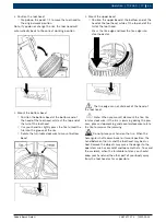
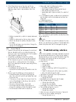
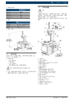
Step down the turntable rotation control pedal
7-4, the turntable will rotate clockwise. And rise
up the turntable rotation control pedal 7-4, the
turntable will rotate counterclockwise.
$
Step down the horizontal arm control pedal 7-1
to the lowest position and the horizontal arm will
swing out. Go on to step down the horizontal arm
control pedal to highest position the horizontal
arm will swing back to the vertical position.
$
Step down the blade control pedal 7-3, the blade
will work and release the blade control pedal 7-3,
the blade will back to its original position.
$
Step down the clamping jaw open/close control
pedal 7-2 to the first gear and the clamping jaw
will open. Step down the clamping jaw open/
close control pedal 7-2 to the second gear and
the clamping will stop at any moment and Step
down the clamping jaw open/close control pedal
7-2 to the third gear and the clamping jaw will
close.
$
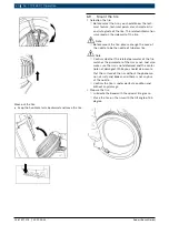
If the horizontal arm at the inmost position,
horizontal will be released and tool head will fall.
When at the middle position, horizontal arm will
be released and tool head will rise up. When at
the outmost position, horizontal arm and tool
head will be locked.
2.
Air treatment assembly
$
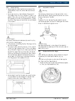
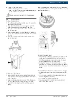
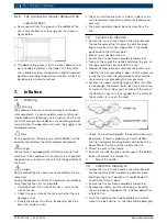
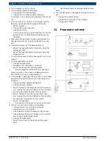
Pressure reducing valve 13-1: Pull out the knob at
the top end of pressure reducing valve A. Clock-
wise/counter clockwise turning can adjust the
feeding pressure of the machine. Press down the
knob A after adjustment.
$
Water separator 13-2: Clockwise/counter clock-
wise turning knob B at the lower end of water
separator can deflate the water in the water cup.
$
Lubricator 13-3: Turning the knob at the top end
of the lubricator. Clockwise/counter clockwise
turning can adjust the oil feeding speed of the
lubricator.
3.
Note
$
The pressure of the machine should he adjusted
in the range of 8-10bar.
$
Regularly deflate the water in the water separator.
$
Move back and forward the blade cylinder and
observe the condition of lubricator. Guarantee the
oil will be fed before operation each day.
6. Operation
6.1
Safety notice
R
This machine is only used to mount/demount the car
tires.
R
The instruction manual must be correct. It is the
integrated part of the machine.
Warning
It is prohibited to use this machine to do the other
work.
The machine is equipped with the tire inflation system.
This function is an independent one. You should pay
more attention to this. Refer to the Chapter "Inflation".
Warning
You must use the original parts of the manufacturer.
Warning
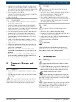
You should keep your hand far away from the point to
be crushed.
Warning
When the accident appears, you should stop the run-
ning of the machine at once.
1.
Plug out the power plug.
2.
Switch the air supply.
6.2
Check before operation
1.
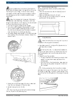
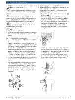
Each time before operate the machine, you should
make the bead breaking cylinder run back and
forward to observe the lubricator and make sure
it starts supply the oil to the air route. After you
confirm that the lubricator works normal, you can
guarantee each part of the air route system under
perfect lubrication.
2.
Check the air treatment assembly to guarantee the
pressure indicated on the pressure gauge of the
pressure reducing valve is not less than 8bar.
3.
Check whether the power supply connection is right
or not.
en


