Solution 6000
Installation Manual
Input Programming
7-11
Bosch Security Systems 07/14 BLCC610I
When the zone loop is open, the system will register the
zone loop as closed or normal.)
Bypass Allowed
Setting this option allows users with the appropriate
access level to manually bypass this zone effectively
removing it from the area for the current arming cycle.
All zone types including 24hour zones can be bypassed if
this option is selected. Bypassed zones will be reset when
the area is turned off or disarmed.
Sensor Watch
Setting this option causes the system to monitor the
zone’s activity while the corresponding area is in the
disarmed state. If the zone fails to unseal and reseal at
least once during the Sensor Watch Time period a system
trouble will be displayed on the keypad and a Sensor
Watch report for the corresponding zone will be sent to
the programmed destination. See MENU 3-9-2 — Sensor
Watch to set the time period.
i
Note
Sensor Watch monitoring is only active when the
area is in the disarmed state. 24 hour zone types
cannot be monitored using the Sensor Watch feature.
Armed In Part On
Setting this option causes the zone to be active or
monitored when the corresponding area is armed Part
On.
If this option is not set, the corresponding zone will be
inactive when the area is armed Part On allowing users to
move freely within this zone and not trigger an alarm.
No EOL Required
Setting this option allows you to connect a zone loop
without the need for an EOL resistor to be fitted as
programmed in the global EOL resistor value.
Test On Exit
Setting this option will cause the system to prompt the
user that a zone or zones are not sealled when they
attempt to arm the area in which the zone belongs.
An error beep will sound and a zone trouble message
will display on the keypad advising the user to seal the
zone(s) or to bypass them before the area will arm.
If this option is disabled the zone will not be tested
during the arming sequence and the system will arm. If
the zone(s) are unsealled at the end of exit time a Zone
Trouble report will be sent.
A D D I N G R F S E N S O R S
The control panel supports a wide range of 3rd party
wireless movement sensors, door contacts and smoke
detectors allowing you to choose the most appropriate
devices for each installation.
In all cases the RF sensor must be compatible with the RF
Receiver that is installed. See MENU 3-5-0 — Input Type.
i
Note
Zones configured as RF zone will follow all other zone
properties.
Inputs > RF Zone >
Add RF Device
MENU 3-3-0
This menu allows you to program an RF device to a zone.
Only one RF device can be used for each zone.
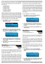
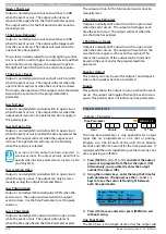
1)
Press [MENU] + [3] + [3] + [0] and use the up and
down arrows to highlight the zone you want to
program in the list and press[OK]. Alternatively, you
can enter the zone number directly and press [OK].
The system will only list zones that dont already
have an RF device programmed.
Enter Device ID Zn1
Zone 1 Name
000000000
Press OK or MENU
2)
Using the numeric keys, enter the RF device ID
number, or trigger the RF device tamper to send
the RF device ID.
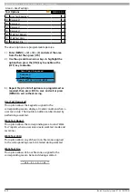
Channel 1
Channel 2
Exit
Press
OK or MENU
3)
Use the [
] and [
] keys to highlight which channel
you want to learn the RF device input (external/
internal contact), then press [OK] to select.
Both channel 1 and channel 2 can only be utilised
by Bosch 3401E and 3405E sensors, allowing you to
utilise both internal and external contacts from the
same device on different zones. All other bosch RF
sensors can only use channel 1.
4)
Press [OK] to save and exit or press [MENU] to exit
without saving.
i
Note
If you require to change a channel, you need to first
delete the RF device ID (see MENU 3-3-1) and add the
RF device again.


