The switching elements of the enabling button are reverse voltage protected.
The outputs of both circuits are protected against short circuits and overload:
Circuit
Function
Circuit 1
Thermal protective circuit
Circuit 2
Fold back line
Fig.7-8:
Short-circuit and overload protection
7.3.3
Functioning
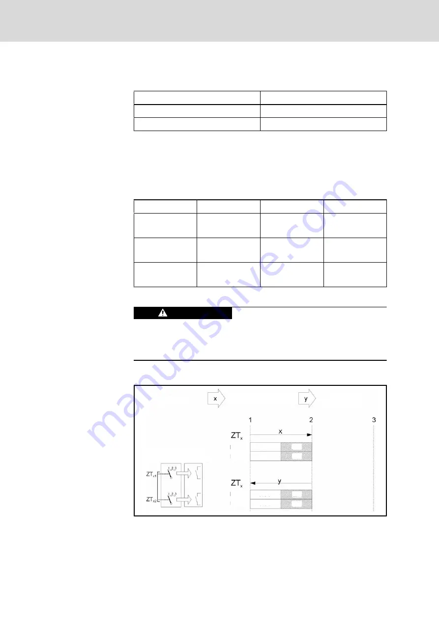
The actuating element consists of two symmetrically arranged slides. The po‐
sition of these slides is detected by electrical switches and transmitted to the
evaluation electronics. The enabling button can have three different switch po‐
sitions, see the following table:
Switch position
Function
Enabling button
Switching contact
1
Home position
Is not pressed
Off
(opened)
2
Enabling
Is pressed
On
(closed)
3
Panic
Is pressed strong
Off
(opened)
Fig.7-9:
Switch positions of the enabling button
Non-functioning enabling device can have le‐
thal consequences!
WARNING
The enabling switch must be tested cyclically (every 6 months) by pressing the
panic position. Watch the machine performing the panic function after pressing
the enabling switch.
7.3.4
Enabling
Evaluation
electronics
Enabling
switch
enabling
home position
home position
Circuit 1
Circuit 2
Circuit 1
Circuit 2
Circuit 1
Circuit 2
OFF
OFF
ON
ON
OFF
OFF
ON
ON
Fig.7-10:
Contact travel diagram for enabling
Bosch Rexroth AG
DOK-SUPPL*-VCH*08.1***-PR02-EN-P
Rexroth IndraControl VCH 08.1 Hand-held Terminal
74/117
Pin Assignments of the IndraControl VCH 08.1


