


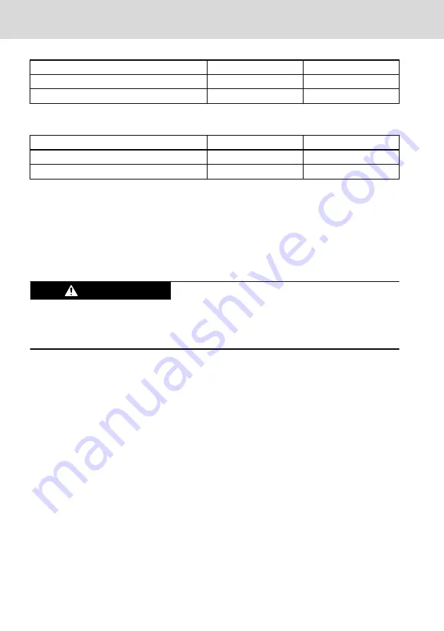
Connector data MSTB 2,5/ 5-STF-5,08
minimum
maximum
Tightening torque
4,43 lbs*inch (0,5 Nm)
5,31 lbs*inch (0,6 Nm)
Wire diameter
26 AWG (0,2 mm
2
)
12 AWG (2,5 mm
2
)
Tab. 9-6: DP connector information
Connector data MC 1,5/ 8-STF-3,5
minimum
maximum
Tightening torque
1,95 lbs*inch (0,22 Nm) 2,21 lbs*inch (0,25 Nm)
Wire diameter
30 AWG (0,14 mm
2
)
14 AWG (1,5 mm
2
)
Tab. 9-7: DP NY4130 connector information
If using wires with an AWG smaller than or equal 12, or a diameter larger than or
equal 2 mm
2
, two pins for (+) and two pins for (–) must be used on the drive
power connector.
9.7 M – Motor connections
Voltage on the pins of this connector can be
higher than 60V DC.
WARNING
Do not touch the pins of this connector.
Do not touch the rear side of the I/O backplane.
Always use shielded cables for motors connected to NYM04.1-2PW-NNNN-
NY4120 and NYM04.1-1HV-NNNN-NY4140 drive modules. Shielded cables for
motors connected to NYM04.1-2LD-NNNN-NY4130 drive modules are not
mandatory, but recommended.
Make sure that the motor cable of suitable AWG marking is used, taking into
account the number of separate wires in the cable and the maximum rated
current.
Every motor cable must be connected on the system housing with a motor cable
shield and support bracket.
Connect the shield at the system housing side to the motor cable shield and
support bracket, and connect the shield at the other end to the motor housing.
If the housing of the connector at the motor side is made of non-conducting
material, connect the shield from the connector at the end of the cable coming
from the system housing side to the metal mounting plate on which that motor
is mounted.
Wire gauge and wire diameter as a function of ambient temperature are derived
from the NFPA-79:2012. Insulation temperature of wires is assumed to be 60°C
(140°F) or 75°C (167°F).
18/45
Interfacing
NYCe 4000 Multi-axis motion control
system
Bosch Rexroth AG R911337318_Edition 09


