tional data carrier (e.g. USB stick) can also be connected to the control. In
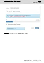
both cases, saving the core dump has to be restarted. First Touch provides
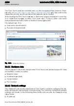
a dialog in the "Core dump" menu item. This dialog allows to select the tar-
get directory if unsaved core dump files are available in the RAM of the
control.
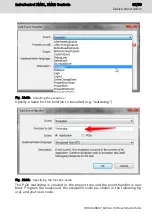
Fig. 12-17: Selecting the target directory to save the core dump
After selecting a valid target directory, press Save to start saving the core
dump. If saving was successful, a corresponding status message is shown.
After closing the dialog, the core dump is displayed with its respective da-
ta.
12.4 Booting
The control starts booting after switching on the 24 V voltage supply. Booting
can be monitored and checked using different LEDs.
The following boot sequence is defined:
1. The LED "U
L
" at the 24 V plug is green if 24 V is connected.
2. The LED "ON" at the 24 V plug is green if the programmable logic is proper-
ly loaded.
3. The LEDs "DIA3" and "DIA4" in the LED block of 10 flash alternatingly in red
while booting.
4. The LEDs "DIA3" and "DIA4" in the LED block of 10 go off after booting and
when the operating system is running.
IndraControl XM21, XM22 Controls
53/69
Device description
R911340667_Edition 04 Bosch Rexroth AG
Summary of Contents for Rexroth IndraControl XM21
Page 1: ...IndraControl XM21 XM22 Controls Operating Instructions R911340667 Edition 04 ...
Page 6: ...IV IndraControl XM21 XM22 Controls Bosch Rexroth AG R911340667_Edition 04 ...
Page 70: ...64 69 IndraControl XM21 XM22 Controls Bosch Rexroth AG R911340667_Edition 04 ...
Page 73: ...IndraControl XM21 XM22 Controls 67 69 R911340667_Edition 04 Bosch Rexroth AG ...
Page 74: ...68 69 IndraControl XM21 XM22 Controls Bosch Rexroth AG R911340667_Edition 04 ...


