6.5
Fuses
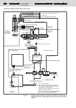
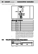
The UPS is provided with 3 fuses. The FKS fuse (4 A, 32 V) can be reached
via the front panel (F1 connection). Both SMD fuses are located on the board.
Refer to Fig. 6-12.
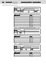
Fig.6-14:
Position of the two SMD fuses
DANGER
Risk to damage the UPS due to short-circuits!
Disconnect the UPS from the power supplies, before opening the device to
check or change a fuse!
If required, unplug all connectors from the VAU.
CAUTION
Risk to damage the UPS by electrostatic discharges!
Comply with all ESD protection measures when a fuse is changed or checked!
Avoid electrostatic discharges!
6.6
Rotary Switch S1
6.6.1
General Information
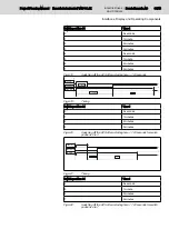
With the rotary switch different UPS times can be set. By using the switch po‐
sition from 0 to 3 the UPS time can be changed in steps of one minute. The
UPS time is the time period in which the connected device is provided with
output voltage of the UPS - after switching off of the input voltage.
Project Planning Manual | Rexroth IndraControl VAU 01.1Z
Electric Drives
and Controls
| Bosch Rexroth AG
29/45
Interfaces, Display and Operating Components

