

7.4
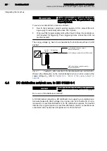
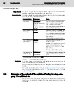
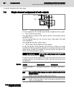
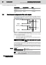
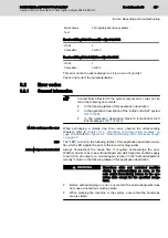
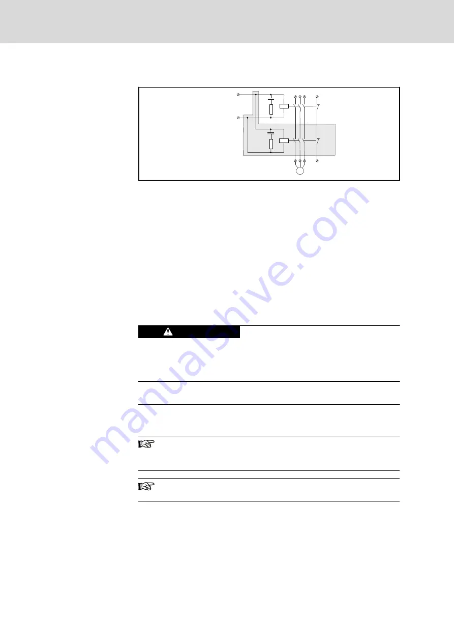
Single-channel assignment of safe outputs
K1
K2
OUT1_Ch1
GND
M
K2 (R)
K1 (R)
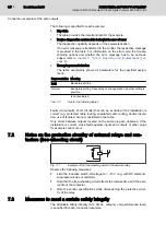
Fig. 7-2:
Single-channel assignment of outputs
To meet category 3 or PL d for the single-channel assignment of the outputs:
●
Use a dual-channel actuator.
The dual-channel connection of the actuator with the corresponding wiring is
highlighted in grey.
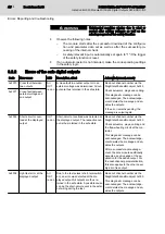
The error detection time is 20 ms. If an error occurs, high pulses of this width
can be generated.
If the application responds to these pulses:
●
Use the dual-channel assignment of the outputs.
K1 (R) and possibly K2 (R) represent the forced N/C contacts to the state
monitoring of the relay (read-back contacts). Connect these contacts via safe
digital outputs. Analyze the readback and thus the state of the switching ele‐
ments in the safe application program.
Loss of the safety function due to parasitic
voltage.
WARNING
Connect the ground of the actuator to the ground terminal point of the corre‐
sponding output on the IndraControl S20 plug. Using an external ground is
not permitted.
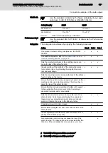
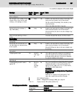
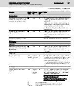
Key data
Actuator
Single-channel
Dual-channel
Attainable SIL/SILCL /
Cat./PL
SIL 2/SILCL 2/Cat. 2/PL c SIL 2/SILCL 2/Cat. 3/PL d
The specified safety category can only be attained under the fol‐
lowing condition:
Switch on the test pulses to attain cat 3 and PL d.
Switch on the test pulses to improve the device diagnostics and in
case of long off-intervals.
Device diagnostics and module
behavior in case of error
Bosch Rexroth AG
DOK-CONTRL-S20*SSDO*8*-AP02-EN-P
36/85
IndraControl S20 Module With Safe Digital Outputs S20-SSDO-8/3
Connection examples of the safe outputs


