


7
Technical data of the components
7.1
Ambient and operating conditions
7.2
Power section
7.2.1
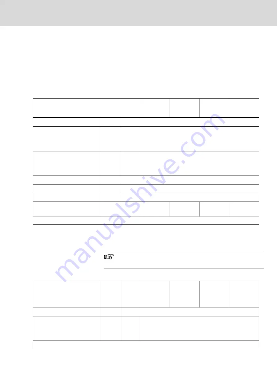
Control voltage
Control voltage supply data
Description
Symbol
Unit
HMU05.1N-
F0140-0350-
N-A4-D7-P
HMU05.1N-
F0170-0430-
N-A4-D7-P
HMU05.1N-
F0220-0510-
N-A4-D7-P
HMU05.1N-
F0270-0660-
N-A4-D7-P
Control voltage input
1)
U
N3
V
24 ±20%
Control voltage when using motor
holding brake with motor cable
length less than 50 m (HCS01
less than 40 m)
2)
U
N3
V
24 ±5%
Control voltage when using motor
holding brake with motor cable
length more than 50 m (HCS01
more than 40 m)
3)
U
N3
V
26 ±5%
Max. inrush current at 24 V supply
I
IN3_max
A
less than 8
Pulse width of I
EIN3
t
EIN3Lade
ms
less than 20
Input capacitance
C
N3
mF
less than 0.01
Rated power consumption control
voltage input at U
N3
4)
P
N3
W
65
48
53
46
Last modification: 2015-12-03
1) 2) 3)
Observe supply voltage for motor holding brakes
4)
See information on "Rated power consumption control voltage
input at U
N3
"
Tab. 7-1:
HMU – control voltage supply data
Rated power consumption control voltage input at U
N3
Plus motor holding brake and control section, plus safety option
Control voltage supply data
Description
Symbol
Unit
HMU05.1N-
F0340-0820-
N-A4-D7-P
HMU05.1N-
F0430-1040-
N-A4-D7-P
HMU05.1N-
F0540-1300-
N-A4-D7-P
HMU05.1N-
F0680-1690-
N-A4-D7-P
Planned
Control voltage input
1)
U
N3
V
24 ±20%
Control voltage when using motor
holding brake with motor cable
length less than 50 m (HCS01
less than 40 m)
2)
U
N3
V
24 ±5%
Last modification: 2015-12-03
DOK-INDRV*-HXX05******-PR02-EN-P
Bosch Rexroth AG
137/407
Rexroth IndraDrive ML Drive Systems with HMU05
Technical data of the components


