


42/68 Installation
Bosch Rexroth AG
, A4VG Series 40, RE 92004-01-B/05.2017
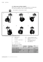
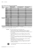
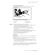
Table 10: Ports A4VG Series 40
Ports
1)
p
max
[bar]
2)
State
6)
A
,
B
Working port
500
O
S
Suction port
5
O
3)
T
1
Drain port
3
O
4)
T
2
Drain port
3
X
4)
R
,
R
1
Air bleed port
3
X
X
1
,
X
2
Control pressure port (upstream of orifice)
40
X
X
1
,
X
2
Control pressure port (upstream of orifice, HT
only)
40
O
X
3
,
X
4
5)
Stroking chamber pressure port
40
X
G
Boost pressure port inlet
40
X
P
S
Pilot pressure port inlet
40
X
P
S
Pilot pressure port (DA..6 only)
40
O
Y
ST
Pilot pressure port outlet
40
X
Y
ST
Pilot pressure port outlet (DA..6 only)
40
O
Y
HT
Pilot pressure port outlet (HT only)
40
O
M
A
,
M
B
Measuring port pressure A, B
500
X
M
H
Measuring port, high pressure
500
X
Y
1
,
Y
2
Pilot pressure port (pilot signal HD only)
40
O
Z
Pilot pressure port (inch signal DA..5 only)
80
O
1)
The measuring system and thread size can be taken from the installation drawing.
2)
Short-term pressure peaks may occur depending on the application. Keep this in mind when
selecting measuring devices and fittings.
3)
Plugged for external boost pressure supply.
4)
Depending on the installation position,
T
1
or
T
2
must be connected (see chapter 7.3 “Installation
5)
Optional
6)
O = Must be connected (plugged when delivered)
X = Plugged (in normal operation)