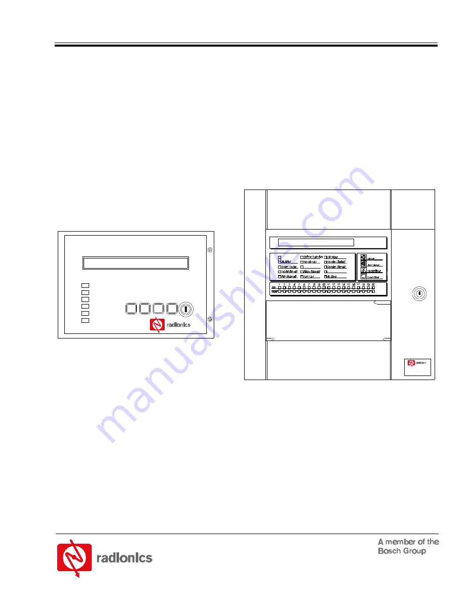
Bosch Radionics D8024 Operator'S Manual Download Page 1

D8024

Analog Fire Alarm Control Panel

Operator’s Guide

POWER

SYSTEM TROUBLE

TROUBLE SILENCED

ALARM SILENCED

POINT BYPASSED

ALARM

System

Reset

Trouble

Silenced

Silence

Alarm

Alarm

Manual

Keypad

Enable

Disable
Keypad

D8024

National Security Systems (800)457-1999 

http://www.nationalsecuritysystems.com 

Summary of Contents for Radionics D8024

Page 1: ...s Guide POWER SYSTEM TROUBLE TROUBLE SILENCED ALARM SILENCED POINT BYPASSED ALARM System Reset Trouble Silenced Silence Alarm Alarm Manual Keypad Enable Disable Keypad D8024 National Security Systems 800 457 1999 http www nationalsecuritysystems com ...

Page 2: ...D8024 D8024 Operator s Guide 35394D Page 2 Copyright 2001 Radionics This page is intentionally blank National Security Systems 800 457 1999 http www nationalsecuritysystems com ...

Page 3: ...14 4 3 Alarm Conditions 14 4 3 1 Alarm Signals 14 4 3 2 Alarm Signal Response 15 4 4 System Operation Main Menu Options 15 4 4 1 System Tests 15 4 4 1 1 LEDs Test 15 4 4 1 2 LCD Test 15 4 4 1 3 Zones Test 16 4 4 2 Time Setting 17 4 4 3 Enable Disable Functions 17 4 4 3 1 Enable Disable by Zone 17 4 4 3 2 Enable Disable Individual Detection Devices Inputs 17 4 4 3 3 Enable Disable Panel Keys 17 4 4...

Page 4: ...re 8 Control Level 2 Controls 14 Figure 9 Main Menu 15 Figure 10 Test Menu 15 Figure 11 Zone Test Menu 1 16 Figure 12 Zone Test Menu 2 16 Figure 13 Zone Test Menu 3 16 Figure 14 Zone Test Menu 4 16 Figure 15 Enable Disable Menus 17 Figure 16 Main Menu 17 Figure 17 Outputs Menu 18 Figure 18 Main Menu 18 Figure 19 View Menu 19 Figure 20 Outputs Submenu 21 Tables Table 1 Control Key Functions 8 Table...

Page 5: ...nerates uses and can radiate radio frequency energy and if not installed in accordance with the instructions may cause harmful interference to radio communications However there is no guarantee that interference will not occur in a particular installation If this equipment does cause harmful interference to radio or television reception which can be determined by turning the equipment on and off t...

Page 6: ...D8024 D8024 Operator s Guide 35394D Page 6 Copyright 2001 Radionics Notes Notices National Security Systems 800 457 1999 http www nationalsecuritysystems com ...

Page 7: ...implify system operation The D8024 includes the following features Analog design using advanced communications protocol 80 character display Custom text annunciation Up to 252 addresses supported in a stand alone system Can be networked with Radionics D9024 and D10024 Analog FACPs as well as other D8024 FACPs 24 VDC 2 5 A power supply and battery charger Programmable sensitivity levels by device P...

Page 8: ... Level 3 2 3 Passcodes Ten passcodes are available for D8024 Controllers Passcodes are programmable The Control Level 2 passcode is assigned or changed from Control Level 3 but will not allow access to Control Level 3 See the Analog Fire Alarm Control Panels Programming Guide P N 38789 for more information on programming and assigning passcodes from Control Level 3 The default Control Level 2 pass...

Page 9: ...ate an option Yes Press to answer Yes or step through an option Table 2 Alphanumeric and Program Interactive Key Functions The upper display the alphanumeric display is an illuminated two line 80 character LED display that gives detailed information on system events and status and displays interactive prompts The middle display the LED display indicates the type of system event and status See Figu...

Page 10: ... an operator This clears when the point s are returned to service Relay Bypassed One or more relays have been disabled manually by an operator This clears when the relay s are returned to service Earth Fault The system has a short circuit to a foreign ground such as an SLC conductor shorted to a heating duct This clears when the fault has been corrected and the panel has been reset Sounder Fault T...

Page 11: ...il message and provide information about the failure the status of the standby batteries and the telephone number for service Pressing the Trouble Silence key will silence the panel buzzer 3 2 Trouble Conditions If a device fails to respond is disabled the response is not within the normal parameters or the system detects a fault the amber System Trouble or Fault LEDs will light The amber Trouble ...

Page 12: ...D8024 D8024 Operator s Guide 35394D Page 12 Copyright 2001 Radionics Notes Control Level 1 National Security Systems 800 457 1999 http www nationalsecuritysystems com ...

Page 13: ...abled for the amount of time programmed into the panel At the end of the programmed time period the panel will automatically inhibit the control keys The following subsections describe specific conditions that may arise while the D8024 is operating and explain how to interface with the panel to resolve these conditions 4 1 Power Conditions The D8024 supervises its AC power supply and standby batte...

Page 14: ...es and zones see Section 4 5 3 Enable Disable Functions After correcting the problem press the System Reset key The amber Trouble Silenced LED will go out and the alphanumeric display will return to normal 4 3 Alarm Conditions The D8024 will signal an alarm if it detects an alarm condition or a fire drill test 4 3 1 Alarm Signals If the D8024 initiates an alarm condition the red Alarm LEDs at the ...

Page 15: ...n is not available to Control Level 2 Operators See the Analog Fire Alarm Control Panels Programming Guide P N 38789 for commissioning and programming information The other options on the Main Menu permit tests and the setting enabling and disabling of various system functions ACTIVE 1 Commission 2 Test 3 Time 1 4 Enable 5 Disable 6 Print 7 View Figure 9 Main Menu 4 4 1 SystemTests Select 2 Test f...

Page 16: ...he moving W across the lower line alternates with a Press NO to EXIT message Note Once the display indicates the panel is in the Walk Test Mode the display will not revert to normal The panel will terminate the test and sound the panel buzzer if there is no activity for a 20 minute period The operator may test devices within the zone parameters shown on the display The panel responds to each test ...

Page 17: ... ZONE AREA display will also light and the panel will display a disable message on the alphanumeric display 4 4 3 2 Enable Disable Individual Detection Devices Inputs To enable or disable input signals from individual detection devices select 2 Input from the Enable Disable Menu The display will prompt for the polling circuit loop number 1 or 2 Key in the circuit number and press Enter The display...

Page 18: ...ng 4 Day Modes from the Enable or Disable Menu will return the alphanumeric display to the Main Menu 4 4 3 5 Enable Disable Relays Select 5 Disable from the Main Menu to disable relays during testing The panel will then display the Disable Menu Select 5 Outputs The display shows the following 1 Sounders 2 Relays ENABLED ENABLED Figure 17 Outputs Menu Note NAC devices such as bells horns and strobe...

Page 19: ...Log Select 2 Log from the View Menu and press Enter The display prompts a beginning entry number The default is the latest entry Press Yes to accept the prompt Press No to select another entry Use the keys to scroll through the log Exit this menu by pressing the No key 4 4 4 3 View Faults This option displays the panel fault status This is the same display as the normal alphanumeric display withou...

Page 20: ...D8024 D8024 Operator s Guide 35394D Page 20 Copyright 2001 Radionics Control Level 2 Notes National Security Systems 800 457 1999 http www nationalsecuritysystems com ...

Page 21: ... is required to enable NAC devices From the Main Menu select 5 Disable The Disable Menu is displayed Select 5 Outputs The display shows 1 Sounders 2 Relays ENABLED ENABLED Figure 20 Outputs Submenu Select 1 Sounders The display prompts for the Control Level 3 passcode Enter the passcode The panel buzzer will sound the System Trouble LED will light and the display message will indicate that the out...

Page 22: ...D8024 D8024 Operator s Guide 35394D Page 22 Copyright 2001 Radionics Notes Control Level 2 National Security Systems 800 457 1999 http www nationalsecuritysystems com ...

Page 23: ...tion Devices 17 Enable Disable Panel Keys 17 Enable Disable Relays 18 Test LEDs Test 15 Tests LCD Test 15 System Tests 15 Zones Test 16 Time Setting 17 View Functions View Devices 19 View Disablements 19 View Event Log 19 View Faults 19 View Outputs 19 View System Events 19 Menus Control Level 2 Entry Menu 1 13 Control Level 2 Entry Menu 2 13 Enable Menu 13 Enable Disable Menus 17 Main Menu 13 15 ...

Page 24: ...on of Detection Systems Inc P N 35394D 8 01 PO Box 80012 Salinas CA 93912 0012 USA Operator s Guide D8024 Customer Service 800 538 5807 Page 24 of 24 National Security Systems 800 457 1999 http www nationalsecuritysystems com ...

Reviews: