background image

Bosch Security Systems | 2011-02

Praesideo 3.5

 | Installation and User Instructions | 8 | Software

en

 | 313

8 Go  to 

Start

 > 

Programs

 > 

Bosch > Praesideo

 > 

FT 

Application 

to start the Praesideo 

File Transfer 

Application

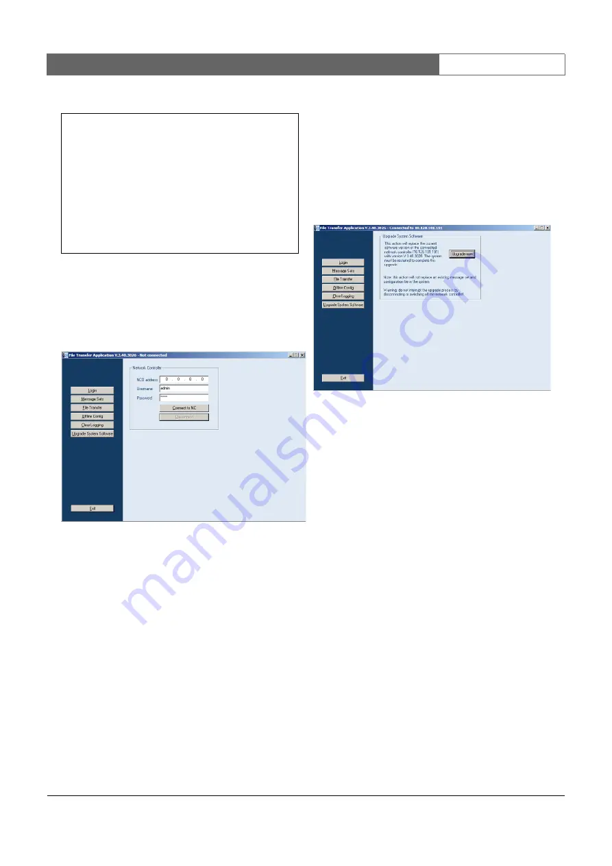
. A screen similar to the one in figure 36.4 

appears.

9 Enter the IP address of the network controller in the 

NCO address 

field.

10 Enter the correct user name in the 

Username 

field and 

the correct password in the 

Password 

field.

If no software has been transferred to the network 
controller before, the default user name is 

target


and the default password is 

password

.

If software has been transferred to the network 
controller before, the default user name is 

admin


and the default password is 

admin

.

11 Click the 

Connect to NC

 button to establish a 

connection with the network controller. A 
notification appears.

36.4  Upgrade system software

A number of the system files that have been installed on 
the configuration PC (see section 36.2), must be 
transferred to the network controller. Proceed as 
follows: 

1 Click the 

Upgrade system software

 button. A screen 

similar to the one in figure 36.5


appears. 

2 Click the 

Upgrade now 

button. A notification is 

displayed when the file transfer process is finished. 

3 Switch the network controller off and then on to 

restart.

figure 36.3: Correct communication

figure 36.4: Connecting to the network controller

Microsoft Windows 2000 [Version 5.00.2195]
(C) Copyright 1985-2000 Microsoft Corp.

C:\>ping 192.168.0.15

Pinging 192.168.0.15 with 32 bytes of data:

Reply from 192.168.0.15: bytes = 32 time<10 ms  TTL=128

Ping statistics for 192.168.0.15:
    Packets: Sent = 4, Received = 4, Loss = 0 (0% loss)

Approximate round trip in milli-seconds:
    Minimum = 0 ms, Maximum = 0 ms, Average = 0 ms

figure 36.5: File transfer screen

Summary of Contents for Praesideo 3.5

Page 1: ...Praesideo 3 5 Installation and User Instructions Digital Public Address and Emergency Sound System en ...

Page 2: ...Bosch Security Systems 2011 02 Praesideo 3 5 Installation and User Instructions en 2 Intentionally left blank ...

Page 3: ...een tested and found to comply with the limits for a Class A digital device pursuant to Part 15 of the FCC Rules These limits are designed to provide reasonable protection against harmful interference when the equipment is operated in a commercial environment This equipment generates uses and can radiate radio frequency energy and if not installed and used in accordance with the instruction manual...

Page 4: ...Bosch Security Systems 2011 02 Praesideo 3 5 Installation and User Instructions en 4 Intentionally left blank ...

Page 5: ...entation 75 1 4 Alerts 75 1 5 Signs 75 2 System overview 76 2 1 Introduction 76 2 2 User friendly software control 76 2 3 Networked approach 76 2 4 Distributed control 76 2 5 Combination of functions 76 2 6 Evacuation compliance 77 2 7 External interfaces 77 2 8 Reduced installation costs 77 2 9 High system flexibility 77 3 Calls 78 3 1 Introduction 78 3 2 Call attributes 78 3 3 Types 79 4 Glossar...

Page 6: ...llation 145 8 6 Using the configuration menu 146 8 7 Configuration and operation 149 8 8 Technical data 151 9 PRS 16MCI Multi Channel Interface 157 9 1 Introduction 157 9 2 Controls connections and indicators 158 9 3 Connectors 159 9 4 Installation 162 9 5 Configuration and operation 162 9 6 Technical data 164 10 Basic Amplifiers 166 10 1 Introduction 166 10 2 Controls connections and indicators 1...

Page 7: ...ypad 208 16 1 Introduction 208 16 2 Controls connectors and indicators 208 16 3 Configuration 209 16 4 Installation 210 16 5 Operation 211 16 6 Technical data 211 17 PRS CSNKP Numeric Keypad 212 17 1 Introduction 212 17 2 Compatibility 212 17 3 Controls connectors and indicators 212 17 4 Bottom view 212 17 5 Installation 213 17 6 Operation 214 17 7 Technical data 215 18 LBB4433 00 Call Station Kit...

Page 8: ... Key Covers 260 Part 6 Installation Accessories 261 25 PRS NSP Network Splitter 263 25 1 Introduction 263 25 2 Controls and connectors 263 25 3 Connections 266 25 4 Installation 267 25 5 Operation 267 25 6 Technical data 268 26 PRS FIN PRS FINNA PRS FINS Fiber Interface 269 26 1 Introduction 269 26 2 Controls connectors and indicators 269 26 3 Connections 271 26 4 Installation 274 26 5 Technical d...

Page 9: ... capacity calculation 304 33 4 Power sources 305 33 5 Cooling capacity 306 34 Preventive maintenance 307 34 1 Clean air inlets 307 34 2 Change battery 307 Part 8 Software 309 35 PRS SW Praesideo Software DVD 311 35 1 Introduction 311 35 2 Starting the DVD 311 35 3 Contents 311 36 Mandatory packages 311 36 1 Introduction 311 36 2 Installation on PC 311 36 3 Establishing connection 312 36 4 Upgrade ...

Page 10: ...rface 336 42 8 CobraNet interface 336 42 9 TCP IP device 337 42 10 Multi Channel Interface 338 42 11 Call Stacker 338 43 Equipment configuration 339 43 1 Introduction 339 43 2 Network controller 339 43 3 Power amplifier 346 43 4 Call station 352 43 5 Audio expander 360 43 6 Fiber interface 361 43 7 CobraNet interface 361 43 8 Multi Channel Interface 363 44 System wide settings 368 44 1 Introductio...

Page 11: ...ck configuration 409 Part 10 Events 411 51 Overview 413 51 1 Introduction 413 51 2 General events 413 51 3 Call events 413 51 4 Fault events 413 52 General events list 415 53 Call events list 418 54 Fault events list 419 Part 11 Optional Software 433 55 CobraNet Discovery 435 55 1 Introduction 435 55 2 Installation 435 55 3 Network adapter configuration 436 55 4 Operation 436 55 5 Menus 438 55 6 F...

Page 12: ...3 Installation 461 59 4 Start 461 59 5 Configuration 461 60 PC Call Station Client 474 60 1 Introduction 474 60 2 Requirements 474 60 3 Installation 474 60 4 Licensing 474 60 5 Start 474 60 6 User Interface 475 61 PC Telephone Interface Client 480 61 1 Introduction 480 61 2 Requirements 480 61 3 Installation 480 61 4 Licensing 480 61 5 Start 480 61 6 Operation 481 61 7 Voice response menu 481 61 8...

Page 13: ...n accordance with the safety concept and need to be registered in the system documentation If third party components not delivered by Bosch Security Systems are added to the minimal configuration of Praesideo then the EN60849 1998 EN54 16 2008 and ISO7240 16 2007 certification becomes expired Only use Power Supply Equipment that is compliant to the current standards and legislation in combination ...

Page 14: ...Bosch Security Systems 2011 02 Praesideo 3 5 Installation and User Instructions Emergency Sound Systems en 14 List of authorized end users Name Name ...

Page 15: ...tem shall be able to broadcast attention drawing signals and speech messages to one or more areas simultaneously There shall be at least one appropriate attention drawing signal alternating with one or more speech messages for this purpose Compliant if attention drawing signal is part of the pre recorded message Responsibility of the installer f At any time the system operator shall be able to rec...

Page 16: ...y of the installer 2 no emergency detection zone shall contain more than one emergency loudspeaker zone For non emergency use a loudspeaker zone may be subdivided Compliant if properly installed Responsibility of the installer m A secondary power source shall be available see 5 6 Compliant if properly installed Responsibility of the installer Requirement Compliance Signature The person or body hav...

Page 17: ...ints to allow a Starting or stopping of pre recorded alarm messages Compliant if properly installed Running message can be overridden by higher priority manually started messages b Selection of appropriate pre recorded alarm messages Compliant if properly installed Manual selection of pre recorded alarm messages is supported c Switching on or off of selected loudspeaker zones Compliant if properly...

Page 18: ...ilability Compliant Indication on call stations if properly installed b Power supply availability Compliant Indication on call stations if properly installed c Any fault condition Any fault is indicated by a control output of the Network Controller if properly installed d For systems having numerous loudspeaker zones which loudspeaker zones are selected and the mode of operation of each zone i e e...

Page 19: ...sponsibility of the installer Visual alarm device must provide feedback to control input l Failure of a processor to correctly execute its software program Compliant using the control outputs of the Network Controller m Detection of any error during memory checking Compliant Program memory is checked on correctness via checksum during system start up Fault is indicated by a control output of the N...

Page 20: ...ervicing personnel or Compliant ii automatically reset the equipment and give an audible and visual warning that an automatic reset has occurred Requirement Compliance Signature The communication link between the emergency detection system and the sound system shall be continuously monitored for faults This is normally performed by the control equipment for the emergency detection system which giv...

Page 21: ...ystem is capable of operation in emergency mode for 30 min when the building is re occupied Responsibility of the installer Non emergency functions within the system such as background music shall not operate from the secondary power supply if this will reduce the capacity for emergency operation Compliant if properly installed Responsibility of the installer If batteries are used as a secondary p...

Page 22: ...20 C to 55 C Relative humidity 25 to 99 Air pressure 86 kPa to 106 kPa Requirement Compliance Signature Equipment shall be permanently marked with information regarding its function Compliant Terminals and controls shall be permanently marked with information regarding their function characteristics and polarity Compliant The marking shall be such that it shall be possible to adjust the user contr...

Page 23: ...n and or alarm the cabling shall be of a standard suitable for the application Responsibility of the installer Precautions shall be taken to prevent the spread of hazardous effects via the wiring routes Responsibility of the installer When a sound system for emergency purposes is installed in combination with an emergency detection system the installation standards for the sound system shall compl...

Page 24: ...nd or maintenance company contracted by the end user in accordance with relevant international and national standards These shall comprise as a minimum a Installation Responsibility of the installer 1 details of the locations of all items of the equipment Responsibility of the installer 2 as installed performance measurements of the system including Responsibility of the installer measured loudspe...

Page 25: ...rement Compliance Signature A stiff covered maintenance manual should be available giving details of all work required to maintain the installation and equipment in proper working order consistent with specified performance criteria and any other requirements of this standard and other relevant international or national standards This should state clearly Responsibility of the installer to establi...

Page 26: ...Bosch Security Systems 2011 02 Praesideo 3 5 Installation and User Instructions EN60849 1998 en 26 Intentionally left blank ...

Page 27: ...d 4 2 Combined VACIE and CIE When the VACIE and CIE are combined they may share common indications manual controls and outputs see Annex F In this case the following shall apply a single fault in the CIE shall not adversely affect the mandatory functions of the VACIE b indication s and manual control s of the voice alarm condition shall be clearly identifiable with the exception of the optional au...

Page 28: ... menu if both conditions apply to the system simultaneously To indicate the voice alarm condition per zone the installer shall use a call station keypad kit with correctly connected red LEDs see clause 13 9 1 with configuration of the Zone status fault warning condition The fault warning condition is indicated per system on each call station power fault LED and on the display of the network contro...

Page 29: ...acklight of the display is on when the component is supplied with power 5 4 2 Where the VACIE is distributed in more than one cabinet an indication of supply of power to each distributed cabinet shall be given at that point The Praesideo system can be distributed in more than one cabinet depending on the installation of the system Many system components can be mounted in a 19 rack Each cabinet wil...

Page 30: ...will pop up on the display of the network controller In the quiescent condition no red indicators are used at all and the display of the network controller will never automatically switch to the emergency menu fault warning condition If the Praesideo system enters the fault warning condition each call station will show a yellow blinking or on power fault LED and the faults menu will pop up on the ...

Page 31: ...e of the transmission path between the CIE and the Praesideo system is limited to fault reporting and losing interaction between the CIE and the Praesideo system 7 2 Indication of the voice alarm condition Praesideo is compliant 7 2 1 The presence of a voice alarm condition shall be indicated on the VACIE without prior manual intervention by a a visible indication by means of a separate discrete l...

Page 32: ...ogrammable timer which shall be configurable at access level 3 g a separate discrete light emitting indicator and or a field on the alphanumeric display shall be visible when a fire signal is received and the delay activated This indication shall be suppressed when the VACIE enters the voice alarm condition 7 5 Phased evacuation option with requirements Praesideo is compliant The VACIE may have a ...

Page 33: ...all still running alarm calls 7 7 2 2 Following a reset operation the indication of the correct functional condition corresponding to any received signals shall either remain or be re established within 20 s After a reset operation the Praesideo system will immediately indicate the functional condition it is currently in It will also immediately respond to received signals that will bring it into ...

Page 34: ...e Praesideo system transmits a signal that it is in the voice alarm condition via control output contacts and the Open Interface An output contact must be configured as voice alarm activated indicator Emergency alarm indicator The Praesideo system then activates the output contact when it enters the voice alarm condition and deactivates the output contact when it leaves the voice alarm condition i...

Page 35: ...the fault warning condition clearly visible from the front side of the rack behind the glass door of the rack b a visible indication for each recognised fault as specified in 8 2 3 8 2 4 8 3 if provided 8 4 if provided and 8 5 and The Praesideo system offers two ways of visual indication of individual faults via the front panel menu of the network controller and via the Praesideo logging applicati...

Page 36: ...cators for fault and voice alarm conditions The only exception is that the automatic indication of the voice alarm condition has precedence over the automatic indication of the number of present faults on the display of the network controller 8 2 4 The following faults shall be indicated at least by means of the general fault warning indicator a any short circuit or interruption in a voice alarm t...

Page 37: ... the fault has occurred Praesideo provides zone fault status indicators assigned to keypad kits One or more zones can be configured to control such an indicator 8 5 System fault Praesideo is compliant A system fault is a fault as specified in 14 4 Program monitoring see also Annex C or 14 6 Monitoring of memory contents in the case of software controlled VACIE A system fault may prevent requiremen...

Page 38: ...t panel menu of the Network Controller and via the Open Interface Acknowledging and or resetting all faults in one action can be done via the front panel menu of the network controller control input contacts call station keys or the Open Interface 8 7 2 Following reset as specified in 8 7 1 the indication of the correct functional conditions corresponding to any received signals shall either remai...

Page 39: ...sablements 9 3 1 Disablements shall either be indicated within 2 s of the completion of the manual operation or where a disablement cannot be completed within 2 s it shall be indicated within 2 s that the disabling process is running 9 3 2 The same light emitting indicator may be used as that for the indication of the corresponding fault although the indication shall be distinguishable 9 3 3 If th...

Page 40: ...lated indications are based on the priority of the active call in the voice alarm zones This means that the lower priority boundary of the Zone status indicator for each zone should be set to include all priorities of possible alarm calls into that zone Using priority level 224 as lower boundary is a safe choice because then the Zone status indicator will cover all possible alarm priorities 224 25...

Page 41: ...ber of present faults This fault indication overrules the normal display information b an indication for each voice alarm zone and or an indication for defined group s of zones The key indicators on call station keypad kits or regular keypads can be configured for Zone status to show that a voice alarm is active for a specific zone or group of zones A second key indicator for this Zone status func...

Page 42: ...able functionality b the mandatory functions of the VACIE shall not be overridden The Praesideo system operates as an autonomous system All external activations are priority based to control preference By proper configuration system behavior is tightly controlled and the mandatory functions of the VACIE will not be overridden c any short circuit interruption or earth fault in the transmission path...

Page 43: ...on keypad key The actual way of operation is defined in the system and is subject to configuration c where a pre announcement attention drawing signal is provided an indicator adjacent to the microphone shall show when the signal has finished and live speech can commence and A call station has a call status LED This LED is blinking green when a pre announcement attention signal or pre recorded mes...

Page 44: ...rity levels are available in the range 224 to 255 highest Higher priorities overrule lower priorities in case of resource or destination conflicts Calls with the same priority operate on first come first serve basis except in the case of priority 255 calls with the same priority 255 overrule each other so the latest becomes active This assures that high priority microphones that are left behind in...

Page 45: ... of EN 60721 3 3 1995 A2 1997 This is verified by means of testing and is documented in the test reports The 19 racks for Praesideo are part of the system and subject to certification A rack must be selected from the list of approved racks for this purpose 13 2 Documentation Praesideo is compliant 13 2 1 The manufacturer shall prepare installation and user documentation which shall be submitted to...

Page 46: ...proved racks 13 3 2 All interconnections and settings inside the cabinet shall be accessible at level 3 The installer must ensure that the physical access to the Praesideo system is restricted to access level 3 then accessibility to all interconnections and settings inside the cabinet e g interconnections between the system elements is restricted to this access level 13 3 3 The VACIE may be housed...

Page 47: ... VACIE or of any other voice alarm transmission path The Praesideo system has the following voice alarm transmission paths between itself and other parts of the voice alarm system transmission path between CIE and Praesideo system via input contact or Open Interface transmission path between Praesideo system and the loudspeaker s If there is a fault in the transmission path between the CIE and an ...

Page 48: ...the call station interface and the connected remote call station remote call station an external power supply can be connected in order to power the call station externally if the network power supply fails remote call station kit a backup power supply can be connected in order to power the call station externally if the network power supply fails The basic call station does not have a backup powe...

Page 49: ...l access control which restricts access to persons that possess the physical access device e g key access card et cetera This is applicable for Input contacts with physical access control the system components offering the input contacts are located in a room cabinet that is not generally accessible The front panel menu with physical access control the system components that have a front panel men...

Page 50: ...all be visible in an ambient light intensity up to 500 lux at any angle up to 22 5 from a line through the indicator perpendicular to its mounting surface at 3 m distance for the general indications of functional condition at 3 m distance for the indication of the supply of power and at 0 8 m distance for other indications All of the light emitting indicators of the Praesideo system fulfill this r...

Page 51: ... the appropriate control output belonging to this key b yellow for indications of 1 fault warnings and 2 disablements or The Power Fault LED of Praesideo call stations is yellow on or flashing when the system is in the fault warning condition The installer must connect a yellow light emitting indicator to the Fault alarm indicator output contact or another output contact configured for this functi...

Page 52: ...cators that are connected to control output contacts are testable 13 12 Audio performance Praesideo is compliant 13 12 1 Output power The VACIE output power shall be as declared by the manufacturer The output power of the amplifier elements of the Praesideo system Power Amplifiers Basic Amplifiers are specified in the data sheets and in the IUI 13 12 2 Signal to noise ratio The VACIE shall have an...

Page 53: ...ed by default to decrease the risk of loudspeaker transformer saturation for high level low frequency signals The high pass filter must remain enabled The frequency response of all Praesideo sound paths that include microphones is within the specified limits of this clause NOTE The frequency response limits exclude loudspeakers NOTE A bandwidth of 400 Hz to 4 kHz is sufficient to achieve acceptabl...

Page 54: ...r Each power amplifier channel of the Praesideo system has a spare amplifier input The installer shall take care of proper installation and configuration of the amplifiers to match amplifier power and number of channels per amplifier Praesideo takes care of input signal switching to the spare amplifier channel including adaptive sound processing This way the spare power amplifier s will have the s...

Page 55: ...described in a set of Hardware Software Interface documentation Where dynamic memory management is employed a separation shall be implemented between the program site specific data and running data and this shall be described in connection with the method of memory allocation The program is located in separate Flash EPROMs that are reserved for the program executable The message data is stored on ...

Page 56: ...monitored by a processor that is guarded by a hardware watchdog 14 4 3 If the program executes in more than one processor the execution of the routines in 14 4 1 shall be monitored in each processor A monitoring device as in 14 4 4 shall be associated with one or more processors and at least one such processor shall monitor the functioning of any processor not associated with such a monitoring dev...

Page 57: ...pplication requires access level 4 b the alteration of site specific data shall not affect the structure of the program Configuration of the Praesideo system is implemented to be data driven and is not part of the program executable Also transferring message sets to the Praesideo system is data driven and is not part of the program executable Therefore alteration of the site specific data does not...

Page 58: ...all system elements c the type number or other designation of the VACIE The type number of each unit of the Praesideo system is present on the unit itself The installer imust ensure that this type number is legible at access level 1 It shall be possible to identify a code or number that identifies the production period of the VACIE at access level 1 or 2 or 3 The hardware version and production da...

Page 59: ...work controller PRS NCO B has been installed after the installer has completed dated and signed the checklist for EN 54 16 or ISO 7240 16 and has clearly indicated on the VACIE label the year in which the VACIE label actually has been affixed on the cabinet The aforementioned checklists are available in the Installation and User Instructions manual of Praesideo 3 5 The VACIE label shall be clearly...

Page 60: ...ed top fans and a lockable swing frame with a maximum height of 40 HU The list of approved cabinets is subject to change The most recent version of this list can be found on www boschsecurity com Main trademark Main product description Main type designation Hardware release Software release Bosch Network Controller PRS NCO B 21 05 3 5 Bosch Audio Expander LBB4402 00 16 15 3 5 Bosch Multichannel In...

Page 61: ...ocessing of alarm signal 7 1 4 Where the s s c i e is used for non emergency purposes the voice alarm condition shall disable or override any functions not connected with the emergency functions Upon entering the emergency mode Praesideo can be configured to override non emergency functions based on priority settings 7 2 Alert signal Optional function 7 2 1 The s s c i e may produce one or more al...

Page 62: ... possibility to store and select custom voice messages to satisfy specific mandated national requirements 7 5 Audible warning Optional function 7 5 3 The audible warning shall be silenced automatically when the s s c i e is reset from the voice alarm condition Praesideo silences the audible warning signal upon acknowledge of the voice alarm condition Acknowledge and reset can be combined in a sing...

Page 63: ... light emitting indicator may be used as that for the indication of the corresponding fault although the indication shall be distinguishable The same light emitting indicator and the same indication may be used to indicate a disabled emergency loudspeaker zone and an emergency loudspeaker zone under test The optional disablement condition is not supported by the Praesideo system Clause Requirement...

Page 64: ... assignment of emergency loudspeaker zones to calls that may contain live speech or prerecorded messages This assignment can be manually during operation or in advance during configuration 13 2 Microphone priority Optional function 13 2 2 Where more than one microphone is configured at each priority level only one microphone shall be active at any one time If more than one microphone at the same p...

Page 65: ...tion either by installing them on a single cabinet or on adjacent cabinets that are mounted in physical contact with each other 14 8 Indications on alphanumeric displays 14 8 2 Alphanumeric displays used for mandatory indications shall have at least one clearly distinguishable window consisting of at least two clearly identifiable fields The display of the network controller is used to display man...

Page 66: ...can be found on www boschsecurity com The network controller and all amplifiers are supplied with a mains supply and DC backup supply 48V input Switch over between the both takes place automatically without any interruption or status change other than the power supply related indications The installer must ensure that the output voltages of the power supply equipment do not exceed the specificatio...

Page 67: ...eo system enters the voice alarm condition the display of the network controller will automatically show the Emergency menu This indication stays on as long as the system is in the voice alarm condition i e until the voice alarm condition is reset If the Praesideo system enters the fault warning condition the display of the network controller will automatically show the Faults menu with the curren...

Page 68: ... subjected to all the operational tests which may be carried out in any order The second specimen shall be subjected to one of the endurance tests and the third specimen shall be subjected to the other endurance test Before and after each environmental test a functional test shall be carried out For the first specimen the functional test after one environmental test may be taken as the functional ...

Page 69: ...not part of ISO7240 16 Clause Requirement Compliance Signature EN54 16 clause 13 4 1 Electrical and other design requirements The processing of signals shall give the highest priority to the voice alarm condition This clause is not part of ISO7240 16 EN54 16 clause 13 13 Message store s Pre recorded messages shall be stored in non volatile memory that retains the messages when all power sources ar...

Page 70: ...Bosch Security Systems 2011 02 Praesideo 3 5 Installation and User Instructions ISO7240 16 2007 en 70 Intentionally left blank ...

Page 71: ...Amplifier 8 x 60 W Yes Yes Yes LBB4430 00 Call Station Basic Yes Yes Yes LBB4432 00 Call Station Keypad Yes Yes Yes PRS NKP Call Station Numeric Keypad Yes Yes Yes PRS CRF Call Stacker Yes Yes Yes LBB4433 00 Call Station Kit Yes Yes Yes LBB4434 00 Call Station Keypad Kit Yes Yes Yes PRS CSI Call Station Interface Yes Yes Yes PRS CSR Remote Call Station Yes Yes Yes PRS CSRK Remote Call Station Kit ...

Page 72: ...Bosch Security Systems 2011 01 Praesideo 3 5 Installation and User Instructions Praesideo on Ships en 72 Intentionally left blank ...

Page 73: ...Bosch Security Systems 2011 02 2011 02 Installation and User Instructions 2 Introduction en 73 Part 2 Introduction ...

Page 74: ...Bosch Security Systems 2011 02 2011 02 Installation and User Instructions 2 Introduction en 74 Intentionally left blank ...

Page 75: ...ated documentation The following related documents are available Release notes on the DVD Commercial Brochure on the website www boschsecurity com Data Brochure on the website www boschsecurity com Architect s Engineer s Specification on the website www boschsecurity com 1 4 Alerts In this manual four types of alerts are used The alert type is closely related to the effect that may be caused when ...

Page 76: ...ed before exiting from any stage of the configuration process 2 3 Networked approach The system architecture is based on daisy chaining of units It is possible to add or remove equipment anywhere in the network without affecting the performance of other units provided that the network connection is available This makes the system easily expandible by the customer without adding any additional elec...

Page 77: ...act closures via the control inputs The configuration allows the user to configure the input to initiate the desired actions in the system The flexibility to route any input from one system unit to another makes it possible to use the Praesideo range of products or a wide range of public address and emergency sound system applications 2 8 Reduced installation costs The Praesideo architecture uses ...

Page 78: ... chime Prerecorded message s Live speech An end chime 3 2 4 Routing The routing of the call is the set of zones to which the call is intended to be addressed Whether the call actually is addressed to the selected zones depends on the priority of the call see section 3 2 2 and its routing scheme Each call can have one of the following routing schemes Partial Non partial Stacked By definition partia...

Page 79: ...nnel interfaces see section 9 and 10 A multi channel interface occupies only 1 node and can drive 14 independent voice alarm zones For response time reasons it is recommended not to use more than 20 multi channel interfaces in a system Together with the other power amplifiers and call stations this yields a practical limit of some 400 voice alarm zones in a single system 3 3 Types 3 3 1 Introducti...

Page 80: ...over distances 50 m in the Praesideo network LCD Liquid crystal display Type of display LED Light emitting diode Electronic component frequently used as indicator LSP Loudspeaker LSZH Low smoke zero halogen MAC address Media access control address Unique hardware address MCI Multi channel interface MTBF Mean time between failures NCO Network controller NC Normally closed Control output behavior Wh...

Page 81: ...Bosch Security Systems 2011 02 Praesideo 3 5 Installation and User Instructions 3 Control Equipment en 81 Part 3 Control Equipment ...

Page 82: ...Bosch Security Systems 2011 02 Praesideo 3 5 Installation and User Instructions 3 Control Equipment en 82 Intentionally left blank ...

Page 83: ... network controller also provides the power to the system and keeps the configuration for all elements in the system The network controller is the interface to other systems See figure 5 1 for a block diagram of the network controller figure 5 1 Block diagram of the network controller A D D A Network Processor DSP Display Control Power Supply Audio Outputs Audio Inputs Control Inputs POF POF Ether...

Page 84: ...nector see section 5 3 6 7 Audio outputs Four audio outputs for extracting analog audio signals Each audio output has a XLR as well as a double cinch connector see section 5 3 7 8 Voltage selector A switch to select the local mains voltage see section 5 3 2 9 Mains on off switch A switch to switch the network controller on and off see section 5 3 2 10 Fuse holder A fuse holder with a fuse that pro...

Page 85: ... 3 1 2 3 4 5 6 7 8 C NC NO C NC NO C NC NO C NC NO C NC NO 1 2 48V Audio Out 3 Audio In 4 Audio Out 4 Audio In 1 Audio Out 1 Audio In 2 Audio Out 2 Mains 0 115 230 T2 5A 250V Battery 48V 4 A Control Out RS 232 1 2 3 4 5 48V Avis Caution Risk of electric shock Do not open Risk of electric shock Do not open O I 115 100 120V 50 60Hz 230 220 240V 50 60Hz T2A H 250V 13 7 11 6 6 7 6 7 6 7 15 14 12 16 17...

Page 86: ...mper that connects the signal ground to the safety ground 19 Compact flash card A connector for a compact flash card for storage of messages see section 5 3 11 A stored message set can hold up to 1024 messages The system can play up to four messages in the set simultaneously as part of a call All of these calls may use the same message if required time shifted or not figure 5 3 Internal view of th...

Page 87: ...e unit The back up supply input is protected against voltage reversal The back up voltage range is 43 to 56 V The system voltage from the system bus is a constant 48 V The power supply to the units that receive power from the system bus is not affected by a changing back up battery voltage table 5 1 Voltage selector and fuse Selector Mains voltage V AC Fuse 115 100 120 T2 5A 250V UL 248 230 220 24...

Page 88: ...ust be used to connect both the network controller and the configuration PC to the network 5 3 6 Connecting audio inputs The network controller has 4 audio inputs to interface with analog audio sources Each audio input has two connectors on the rear of the network controller one XLR connector for balanced signals and one double cinch connector for unbalanced signals The network controllers mixes s...

Page 89: ...Praesideo system The control inputs can be configured to act on contact make or on contact break see section 43 2 It is also possible to supervise the cables for short circuits and open connections see figure 5 8 and figure 5 9 Whether a control input is actually supervised or not is defined in the configuration figure 5 6 Audio input sockets table 5 3 Audio input socket details Pin Socket Definit...

Page 90: ...n and development purposes Do not use this connector in installed Praesideo systems with the following exception The PRS NCO B comes with a dedicated buzzer for audible fault and voice alarm notifications This buzzer comes with a connector to power it from the RS232 port See section 32 9 figure 5 9 Non supervised control input Warning Do not connect DC or AC signals to the control inputs otherwise...

Page 91: ... 4 Installation The network controller is suitable for either table top or 19 inch rack installation Four feet for table top use and two brackets for rack installation are supplied Note The electronics inside the network controller are susceptible to electrostatic discharges Wear an anti ESD bracelet during the installation of the compact flash card Warning To prevent the hazard of electric shocks...

Page 92: ...ure gives an overview of the menu structure figure 5 12 Structure of the network controller front panel menu Clock VU meter Emergency Faults Fault Fault Menu Address Setup Monitoring TCP IP Setup MAC Address Serial Number HW Version SW Version FW Version Date Time Subnet Mask Default Gateway Back Back 1 2 N N 1 N 2 2 3 2A 2B 2C 2D 2E 2F 2G Back Acknowledge Reset Back 2Ba 1 2Bb 2Bc 1 Serial Number ...

Page 93: ...rn the button to move through the status screens i e the Clock VU meter Emergency Faults and Menu screens To navigate through the main menu 1 Navigate in the status screens to Menu 2 Push the button to go to the main menu The menu item number starts blinking 3 Turn to select another menu item number 4 Push to confirm the selection To jump to a submenu 1 Navigate to an item with three dots e g Setu...

Page 94: ...le assumes you start from the default screen 1 Turn the button to go to the Menu in the status screens 2 Push the button to confirm 3 Turn the button to go to the Setup submenu 4 Push the button to confirm 5 Turn the button to go to the TCP IP Setup submenu 6 Push the button to confirm 7 Push the button to confirm 8 Turn the button to move the cursor to the first part of the IP address 9 Push the ...

Page 95: ...to confirm 19 Turn the button to change the fourth part of the IP address 20 Push the button to confirm 21 Turn to move the cursor to the menu number 22 Push the button to confirm 23 Turn to move to the Back item 24 Push the button to confirm 25 Turn the button to go to the default screen 2Ba Address 192 000 000 000 2Ba Address 192 000 000 000 2Ba Address 192 168 000 000 2Ba Address 192 168 000 00...

Page 96: ...mation about the emergency state and allow to acknowledge and reset the emergency state see table 5 8 When the emergency state is reset all emergency calls are aborted 5 6 5 Faults menu The Faults menu see figure 5 12 provides access to the faults menu This menu is automatically activated when there is a fault in the system Because the number of active faults in the system can vary the item number...

Page 97: ...chapter 54 to find out the cause of a fault or the recommended action to take 5 6 6 Main menu The Menu item see figure 5 12 provides access to the main menu Note In the next table n indicates the nth fault in the faults menu whereas N indicates the total number of faults in the faults menu table 5 9 Faults menu Menu item Description nA Serial Nr Shows the serial number of the unit that generated t...

Page 98: ...issing Gnd short channel Amplifier ground short Grp A fault channel Group A fault Grp B fault channel Group B fault HW Version Mismatch Hardware version mismatch Internal Fault number Cobranet interface fault Keypad n m mismatch Keypad mismatch Line input audio input Line input failure Loop fault channel Class A switchover Loudspeaker channel Loudspeaker failure Lsp Line channel Amplifier loudspea...

Page 99: ...9 Fault Detail Logging message Sec pwr RCS Backup power supply failure remote call station Supervision channel channel Pilot tone calibration Line supervision master mismatch Supply 24V channel Redundant supply 24V Uncfgd unit Unit not configured Unknwn unit Unknown unit type table 5 11 Faults event table ...

Page 100: ...lue 2 Description 1 Monitoring Source Input n Input nr 1 to 4 Volume 31 to 0 dB The signal from audio input n is available on the monitoring loudspeaker or headphones output Output n Output nr 1 to 4 Volume 31 to 0 dB The signal from audio output n is available on the monitoring loudspeaker or headphones output Off The monitoring loudspeaker or headphones output is off during normal operation tabl...

Page 101: ...version menu items are used to obtain version information about the network controller table 5 15 MAC address menu item Menu item Value read only Description 2C MAC address e g 000463 004209 Show the MAC address of the network controller table 5 16 Version information menu items Menu item Value read only Description 2D Serial Number e g 11 0 008A4 Shows the hexadecimal serial number 2E HW Version ...

Page 102: ...urge immunity Electrical safety IEC60065 CB scheme EN60065 Approvals CE marking EN60849 EN54 16 and ISO7240 16 IEC60945 MTBF 50 000 hours at 55 C The MTBF doubles for every 10 C decrease in temperature Connector rear side Proprietary connector Preferred cable LBB4416 xx Maximum cable length 50 m per system bus connector Data signal interface Plastic optical fiber Network power supply 2 x 55 W at n...

Page 103: ... kHz Distortion 0 05 at 1 kHz at 3 dB of the maximum input level Connector rear side Female XLR per input Preferred cable Shielded Nominal input level 57 dBV based on 91 dBSPL for a microphone with sensitivity of 2 mV Pa a male voice with normal loudness and a speaker to microphone distance of 0 15 m Headroom 30 dB Input range 7 to 8 dB with respect to nominal input level limiter threshold Input s...

Page 104: ... 100 ohm Signal Noise ratio 89 dBA at maximum level Output cross talk 85 dB Distortion 0 05 at 1 kHz at 3 dB of the maximum input signal Connector rear side Removable screw connector Total cable resistance 1 kohm with line supervision 5 kohm without line supervision Resistance detection supervision enabled Cable short circuit 2 5 kohm Contact closed 7 5 kohm to12 kohm Contact open 17 5 kohm to 22 ...

Page 105: ... 5 is a visual fault indication contact for visual fault indications e g lamp The hardware information can be obtained from the front panel menu figure 5 14 Maximum switching power Contact Current A Contact Voltage V 10 20 30 40 50 200 100 0 2 0 3 0 4 0 5 1 0 2 0 Connector rear side Female 9 pole SUB D connector Maximum cable length 15 m Signal levels According to EIA RS232 C interface specificati...

Page 106: ...tems Furthermore control inputs and outputs are available 6 2 Controls connectors 6 2 1 Front view The front of the audio expander see figure 5 2 contains the following 1 Menu display A 2x16 character LCD display gives information about the audio expander see section 6 5 2 Menu button A turn and push button to operate the menu see section 6 5 3 Monitoring headphones output A 3 5 mm 0 14 inch jack ...

Page 107: ... to electrically ground the audio expander 7 System bus Two system bus connectors to connect the audio expander to other Praesideo equipment see section 6 3 2 8 Control inputs The control inputs can be used to receive signals from third party equipment that must trigger actions in the Praesideo network see section 6 3 5 9 Control outputs The control outputs can be used to send signals to third par...

Page 108: ...analog audio can be a line source as well as a microphone See table 6 1 for an overview of the input types supported by each of the inputs See figure 6 3 for details about the audio input sockets 6 3 4 Connecting audio outputs The audio expander has 4 audio outputs to route analog audio signals to other equipment e g a tape deck to record a specific audio signal Each audio output has two connector...

Page 109: ... figure 6 5 and figure 6 6 Whether a control input is actually supervised or not is defined in the configuration figure 6 4 Audio output sockets table 6 3 Audio output socket details Pin Socket Definition Description 1 XLR male Xternal Shield ground 2 Live Positive 3 Return Negative 4 Cinch Right Right channel out 5 Left Left channel out Audio Out 1 3 2 5 4 figure 6 5 Supervised control input figu...

Page 110: ...tion The audio expander is suitable for either table top or 19 inch rack installation Four feet for table top use and two brackets for rack installation are supplied figure 6 7 Control outputs table 6 4 Control outputs details Connection Abbr Description Normally closed NC By default the NC contact is connected with common contact C When the output is activated the NC contact is opened Normally op...

Page 111: ...verview A number of audio expander settings are available via an interactive menu using a 2x16 LCD display and a turn and push menu button The next figure gives an overview of the menu structure figure 6 9 Structure of the audio expander front panel menu Name VU meter Menu Monitoring Setup Serial Number HW Version FW Version Back 1 2 2A 2B 2C Back ...

Page 112: ...ens 1 Turn the button to move through the status screens i e the Name VU meter and Menu screens To navigate through the main menu 1 Navigate in the status screens to Menu 2 Push the button to go to the main menu The menu item number starts blinking 3 Turn to select another menu item number 4 Push to confirm the selection To jump to a sub menu 1 Navigate to an item with three dots e g Setup 2 Push ...

Page 113: ...nes output of the audio expander This example assumes you start from the default screen 1 Turn to the button to go to the Menu in the status screens 2 Push the button to confirm 3 Push the button to confirm 4 Turn the button to the Monitoring option 5 Push the button to confirm 6 Turn the button to change the audio output you want to listen to 7 Push the button to confirm 8 Turn to move the cursor...

Page 114: ... fault the Name screen also shows the fault status see table 6 6 If there is more than one active fault only the most severe fault is shown A fault status only provides global information The exact source of a fault can be found out using the fault events list in this manual see chapter 52 6 6 5 Main menu The Menu item see figure 6 9 provides access to the main menu table 6 5 Status screens Menu I...

Page 115: ...ormation about the audio expander table 6 8 Monitoring submenu Menu item Option Value 1 Value 2 Description 1 Monitoring Source Input n Input nr 1 to 4 Volume 31 to 0 dB The signal from audio input n is available on the headphones output Output n Output nr 1 to 4 Volume 31 to 0 dB The signal from audio output n is available on the headphones output Off The headphones output is off during normal op...

Page 116: ...SO7240 16 IEC60945 MTBF 50 000 hours at 55 C The MTBF doubles for every 10 C decrease in temperature Connector rear side Proprietary connector Preferred cable LBB4416 xx Maximum cable length 50 m per system bus connector Data signal interface Plastic optical fiber Power supply via network 27 to 56 V DC Network power consumption 9 0 W Connector rear side Female galvanically separated XLR and female...

Page 117: ...ce 1360 ohm Signal Noise ratio 62 dBA with 25 dB headroom Common mode rejection ratio 55 dB at 100 Hz 65 dB at 1 kHz and 10 kHz Phantom supply 12 V 1 V max 15 mA Limiter Analog limiter level 8 dB with respect to maximum attack time 1 ms decay time 300 ms threshold at nominal input level Only for audio expanders of version HW15 xx and higher Hardware information can be obtained using the front pane...

Page 118: ... 5 kohm Maximum open voltage 24 V DC Internal pull up current 0 5 mA External contacts Voltage free closing or breaking contacts relay contacts mechanical switches mercury contacts etc Connector rear side Removable screw connector Maximum cable length 1 km Contact type Relay contact single pole change over contact SPDT Maximum switching power Refer to the graph Off state unpowered C NC is closed C...

Page 119: ...twork infrastructure controllers switches cabling etc that operate in compliance with the IEEE 802 3u specification for Fast Ethernet Fast Ethernet distance limitations apply to CobraNet installations 100 meters over Cat 5 copper cable 2 kilometers over multimode fiber Proprietary Fast Ethernet via single mode fiber solutions can reach even further CobraNet can sent up to 64 channels of 48 kHz 20 ...

Page 120: ...ignals to third party equipment to trigger actions generated by the Praesideo network see section 7 4 5 7 4 Connections 7 4 1 Introduction This section gives an overview of typical system connections using the CobraNet interface Connecting the Praesideo network see section 7 4 2 Connecting the CobraNet network see section 7 4 3 Connecting control inputs see section 7 4 4 Connecting control outputs...

Page 121: ...5 Installation and User Instructions 3 Control Equipment en 121 figure 7 2 Front and rear views of the CobraNet interface Network Control In 1 2 3 4 5 6 7 8 C NC NO C NC NO C NC NO C NC NO C NC NO 1 2 48V Control Out 1 2 3 4 5 48V 4 6 7 5 2 1 3 ...

Page 122: ...her pin that is connected is the normally closed NC or normally open NO depends on which action that take place when the control output is active see table 7 1 In the configuration a purpose must be attached to the control output that indicates the action to be taken when it becomes active see table 43 6 figure 7 3 Supervised control input figure 7 4 Non supervised control input Warning Do not con...

Page 123: ...t must be configured using the CobraNet Discovery utility see chapter 55 This application can be run from any PC that is connected to the CobraNet interfaces via an Ethernet network figure 7 6 Installation Note The center bracket positions can be used to secure the unit on a table or shelf They can also be used to install the unit vertically to a wall Caution When mounting the brackets to the unit...

Page 124: ...iew A number of CobraNet interface settings are available via an interactive menu using a 2x16 LCD display and a turn and push menu button The next figure gives an overview of the menu structure figure 7 7 Structure of the CobraNet interface front panel menu Name VU meter Menu Monitoring Setup Serial Number HW Version FW Version Back 1 2 2A 2B 2C Back ...

Page 125: ...ens 1 Turn the button to move through the status screens i e the Name VU meter and Menu screens To navigate through the main menu 1 Navigate in the status screens to Menu 2 Push the button to go to the main menu The menu item number starts blinking 3 Turn to select another menu item number 4 Push to confirm the selection To jump to a sub menu 1 Navigate to an item with three dots e g Setup 2 Push ...

Page 126: ...es output of the audio expander This example assumes you start from the default screen 1 Turn to the button to go to the Menu in the status screens 2 Push the button to confirm 3 Push the button to confirm 4 Turn the button to the Monitoring option 5 Push the button to confirm 6 Turn the button to change the audio output you want to listen to 7 Push the button to confirm 8 Turn to move the cursor ...

Page 127: ...e fault the Name screen also shows the fault status see table 7 3 If there is more than one active fault only the most severe fault is shown A fault status only provides global information The exact source of a fault can be found out using the fault events list in this manual see chapter 45 7 8 5 Main menu The Menu item see table 7 4 provides access to the main menu table 7 2 Status screens Menu I...

Page 128: ...ormation about the audio expander table 7 5 Monitoring submenu Menu item Option Value 1 Value 2 Description 1 Monitoring Source Input n Input nr 1 to 4 Volume 31 to 0 dB The signal from audio input n is available on the headphones output Output n Output nr 1 to 4 Volume 31 to 0 dB The signal from audio output n is available on the headphones output Off The headphones output is off during normal op...

Page 129: ...udio signal might be lost After the burst this signal restores automatically Electrical safety IEC60065 CB scheme EN60065 Approvals CE marking EN60849 EN54 16 and ISO7240 16 IEC60945 MTBF 50 000 hours at 55 C The MTBF doubles for every 10 C decrease in temperature Connector rear side Proprietary connector Preferred cable LBB4416 xx Maximum cable length 50 m per system bus connector Data signal int...

Page 130: ...Bosch Security Systems 2011 02 Praesideo 3 5 Installation and User Instructions 3 Control Equipment en 130 Intentionally left blank ...

Page 131: ...Bosch Security Systems 2011 02 Praesideo 3 5 Installation and User Instructions 4 Amplifiers en 131 Part 4 Amplifiers ...

Page 132: ...Bosch Security Systems 2011 02 Praesideo 3 5 Installation and User Instructions 4 Amplifiers en 132 Intentionally left blank ...

Page 133: ...e amplification of audio signals for the loudspeakers The amplifiers are high efficiency class D amplifiers with switched mode power supply The amplifiers are protected against overload overheat and short circuits See figure 8 1 for a block diagram of the power amplifier The power amplifiers have configurable audio processing functions like parametric equalization audio delay and the possibility f...

Page 134: ...esideo network see section 8 3 7 6 Audio inputs Audio inputs for receiving audio signals from analog audio sources see section 8 3 6 7 Back up power A socket for connecting a back up power supply see section 8 3 8 8 Mains on off switch A switch to switch the mains of the power amplifier on and off see section 8 3 2 9 Fuse holder A fuse holder with a fuse that protects the power supply of the power...

Page 135: ...ol Out Spare In Lsp Out NO NC 0V 50V C Control Out Spare In Lsp Out NO NC 0V 50V 5 7 Avis Caution Risk of electric shock Do not open Risk of electric shock Do not open 11 5 4 6 12 8 9 7 0 Control In 1 2 3 4 5 6 7 8 1 2 Audio In Network 1 2 Control Out Spare In Lsp Out C NO NC 0V 50V 4 3 Control Out Spare In Lsp Out C NO NC 0V 50V Control Out Spare In Lsp Out C NO NC 0V 50V 2 1 Control Out Spare In...

Page 136: ...umper is X3 on the printed circuit board Set the jumper to connect pins 2 and 3 to connect signal ground to the safety ground Set the jumper to connect pins 1 and 2 to isolate the signal ground The manufacturers setting is as a floating ground with the jumper connecting pins 1 and 2 If the audio line or microphone input of the amplifier is used and the connected audio source is not grounded the ju...

Page 137: ...ifier channel connector table 8 4 Amplifier channel connector details Pin Description 1 2 3 Control outputs contacts See section 8 3 5 4 4 8 Spare amplifier See section 8 3 5 5 5 9 Loudspeaker line See section 8 3 5 2 6 7 Fixed 50 V line See section 8 3 5 3 C Control Out Spare In Lsp Out NO NC 0V 50V 1 9 Caution To prevent the hazard of electric shocks switch off the power amplifiers and disconnec...

Page 138: ...put level is 40 dBV If the loudspeaker line voltage is set to 70 V the maximum output level is reduced to 37 dBV difference 3 dB If it is set to 50 V it is reduced to 34 dBV difference 6 dB Caution Check the specifications of the loudspeakers to find out which maximum voltage can be provided on the loudspeakers outputs of the power amplifiers To reduce the risk of electric shock do not perform any...

Page 139: ...you want to take place when the control output is active see table 8 5 In the configuration a purpose must be attached to the control outputs that indicates the action to be taken when it becomes active see table 43 6 For example the power amplifier control outputs can be configured as a Volume override output to create volume overrides 8 3 5 5 Spare amplifiers If a power amplifier has a defect al...

Page 140: ...PRS 4P125 amplifier has been taken over by a spare power amplifier the amplifier goes to stand by the audio inputs do not work but the control inputs and outputs remain active figure 8 7 Connecting a spare amplifier Note It is allowed to connect one spare power amplifier to more than one main power amplifier Control Out Spare In Lsp Out C NO NC 0V 50V Control Out Spare In Lsp Out C NO NC 0V 50V 1 ...

Page 141: ...iguration settings of the first failing power amplifier are transferred to the spare power amplifier 8 3 6 Connecting audio inputs The number of audio inputs depends on the type of power amplifier The audio inputs are used to interface with analog audio sources Each audio input is selectable between line and microphone It is possible to connect unbalanced signal as well as balanced signals Unbalan...

Page 142: ...d open connections see figure 8 11 and figure 8 12 Whether a control input is actually supervised or not is defined in the configuration figure 8 11 Supervised control input figure 8 12 Non supervised control input Control In 1 2 3 4 5 6 7 8 10kΩ 10kΩ Control In 1 2 3 4 5 6 7 8 Warning Do not connect DC or AC signals to the control inputs otherwise the input circuit may be damaged Only use voltage...

Page 143: ... 250V 0 0 Class 2 Wiring Caution Avis Risq of electric shock Do not open Risque de choc electrique Ne pas ouvrir Battery 48V 12A Non isolated input 0 48V 15AT 1 1 2 2 3 4 5 48V 6 7 8 1 2 3 4 0 0 Control In Audio In Network 48V 2 4 48V Battery Mains T6 3A H 250V 100 240V 0 0 6 8 C Control Out Spare In Lsp Out NO NC 0V 50V 1 3 C Control Out Spare In Lsp Out NO NC 0V 50V C Control Out Spare In Lsp Ou...

Page 144: ... two positions Normal factory default The fans are temperature controlled normally running at low speed and switching to high speed in case the temperature exceeds a certain level Fan monitoring is not activated Full speed The fans run at full speed continuously Fan monitoring is activated Do not enable Switch amplifiers to standby see section 44 4 for this selection because in standby the fans ar...

Page 145: ... see figure 8 17 to prevent dust from entering the equipment Caution Due to the weight of the power amplifiers it requires two persons to lift and install them in a 19 inch rack figure 8 16 Installation figure 8 17 Air flow in a 19 rack Caution When mounting the brackets to the unit use the screws that are supplied with the brackets four longer ones and two shorter ones Use two screws of 7 5 mm th...

Page 146: ...rview A number of power amplifier settings are available via an interactive menu using a 2x16 LCD display and a turn and push menu button The next figure gives an overview of the menu structure figure 8 18 Structure of the power amplifier front panel menu Status Menu Monitoring Setup HW Version FW Version Serial Number Back 1 2 2A 2B 2C Back ...

Page 147: ...s screens 1 Turn the button to move through the status screens i e the Status and Menu screens To navigate through the main menu 1 Navigate in the status screens to Menu 2 Push the button to go to the main menu The menu item number starts blinking 3 Turn to select another menu item number 4 Push to confirm the selection To jump to a sub menu 1 Navigate in to an item with three dots e g Setup 2 Pus...

Page 148: ... the power amplifier This example assumes you start from the default screen 1 Turn to the button to go to the Menu in the status screens 2 Push the button to confirm 3 Push the button to confirm 4 Turn the button to the Monitoring option 5 Push the button to confirm 6 Turn the button to change the audio output you want to listen to 7 Push the button to confirm 8 Turn to move the cursor to the menu...

Page 149: ...ut its fault status see table 8 7 If there is more than one active fault only the most severe fault is shown A fault status only provides global information The exact source of a fault can be found out using the fault events list in this manual see chapter 54 table 8 7 Status in order of severity high to low Fault status Description No network The optical network is not available Fault Channel n F...

Page 150: ... Version submenus are used to obtain version information about the power amplifier table 8 8 Main menus Menu item Description 1 Monitoring Go to the Monitoring submenu See section 8 7 5 2 Setup Go to the Setup submenu See section 8 7 6 and further table 8 9 Monitoring submenu Menu item Option Value 1 Description 1 Monitoring Source Output n Output nr 1 to 8 The signal from audio output n is availa...

Page 151: ...eme EN60065 Approvals CE marking EN60849 EN54 16 and ISO7240 16 IEC60945 MTBF 32 000 hours at 55 C The MTBF doubles for every 10 C decrease in temperature Connector rear side Female proprietary connector Preferred cable LBB4416 xx Maximum cable length 50 m per system bus connector Data signal interface Plastic optical fiber Network power consumption 0 W Connector rear side IEC male power inlet wit...

Page 152: ...t tone 15 V 173 W 48 V DC 194 W 120 230 V AC Pmax 3 dB with pilot tone 15 V 327 W 48 V DC 353 W 120 230 V AC Pmax with pilot tone 15 V 589 W 54 V DC 680 W 120 230 V AC Stand by Power save 5 W 48 V DC 16 W 120 230 V AC Idle no pilot tone 19 W 48 V DC 31 W 120 230 V AC Idle with pilot tone 15 V 30 W 48 V DC 43 W 120 230 V AC Pmax 6 dB with pilot tone 15 V 178 W 48 V DC 195 W 120 230 V AC Pmax 3 dB w...

Page 153: ...oise ratio 87 dB rms unweigthed Common mode rejection ratio 40 dB at 1 kHz Input cross talk 80 dB at 1 kHz 70 dB at 10 kHz at 11 dBV input level Distortion 0 1 Connector rear side 6 pole header type ETB47 06 2 G1 ECE for removable screw connector Preferred cable Twisted pair shielded Nominal input signal level 57 dBV Input range 7 to 8 dB with respect to nominal input level Input sensitivity setti...

Page 154: ...age 200 V peak Rated load resistance 100 70 50 V output PRS 1P500 20 10 5 ohm PRS 2P250 40 20 10 ohm PRS 4P125 80 40 20 ohm LBB4428 166 83 42 ohm Rated load capacitance 100 70 50 V output PRS 1P500 250 500 1000 nF PRS 2P250 125 250 500 nF PRS 4P125 60 125 250 nF LBB4428 30 60 120 nF Rated output power a b c d e f operating condition PRS 1P500 1 x 500 425 275 185 185 125 W PRS 2P250 2 x 250 210 150...

Page 155: ...y Praesideo resulting in a required continuous power of 50 of the rated output power This can be delivered for at least 30 minutes at 55 C ambient or continuously at 30 C ambient 8 8 13 Control inputs figure 8 20 Output power derating 55 25 30 35 40 45 50 55 60 50 45 40 35 30 25 20 Continuous Output Power of Rated Output Power T C Connector rear side 16 pole header type Phoenix MC1 5 16 G 3 81 for...

Page 156: ...nput Contact type Relay contact single pole change over contact SPDT Maximum switching power Refer to the graph Off state unpowered C NC is closed C NO is open figure 8 21 Maximum switching power Connector front side 3 5 mm stereo jack socket for headphones Maximum output voltage 6 dBV without volume control Rated load impedance 8 to 600 Ω Signal Noise ratio 80 dB at maximum output level Distortio...

Page 157: ...ng 32 additional control inputs and 16 control outputs The multi channel interface gives supervision to the connected amplifier channels It can be used without connections to a basic amplifier The multi channel interface then gives the Praesideo network 32 more control inputs and 16 more control outputs figure 9 1 Block diagram of a multi channel interface Fail safe D A Network Processor DSP Bypas...

Page 158: ...ti channel interface to other Praesideo equipment 7 Bypass In The multi channel interface bypass input from the Network controller See section 9 3 4 8 Bypass Out The multi channel interface bypass output to next multi channel interface 9 Amplifier connectors 1 14 Connections to the basic amplifier channels to give audio and control signals and receive power and supervision information see section ...

Page 159: ... and LBB4416 network cables to connect the multi channel interface to the Praesideo system Both connectors are interchangeable Normally the multi channel interface receives its power from the connected amplifiers This is the recommended setting but if it is not connected to an Caution Do not connect the circle symbol connector of the multi channel interface to the triangle symbol connector of the ...

Page 160: ...output from the network controller is always activated as a zone as part of emergency calls 4 For supervision of the bypass connection configure the network controller to give a 20 kHz signal on the Audio Out of the network controller A separate 20 kHz pilot tone detector connected to the last by pass out can be used to supervise the interconnection of the bypass connections Bypass from an externa...

Page 161: ... Warning Do not connect DC or AC signals to the control inputs otherwise the input circuit may be damaged Only use voltage free contacts Note Do not combine control input wires of multiple control inputs e g do not use a common return wire 1 8 9 16 17 24 25 32 Control In 1 2 3 4 5 6 7 8 17 18 19 20 21 22 23 24 10kΩ 10kΩ 1 8 9 16 17 24 25 32 Control In 1 2 3 4 5 6 7 8 17 18 19 20 21 22 23 24 ...

Page 162: ...9 5 1 Overview The multi channel interface has these functions Changes the Bypass mode to Normal mode after the multi channel interface starts Refer to 9 5 2 Monitors the status of each basic amplifier Refer to 9 5 3 Monitors the power supply to the basic amplifiers Monitors the line and loudspeaker supervision devices Makes the decision to make a spare amplifier available if an amplifier channel ...

Page 163: ...hannel is put on a waiting list for the spare amplifier channel If more than two main channels are connected to the same spare channel the first amplifier channel to report a fault will receive the spare channel When the first amplifier channel becomes available for use again the spare channel takes over the functions of the second main channel until the second main channel becomes available 9 5 4...

Page 164: ... decrease in temperature Multi channel interface power supply Supplied by either the connected basic amplifier default setting or the Praesideo system bus optional setting Power consumption basic amplifier If the power is supplied by the basic amplifier the power consumption of the basic amplifier is increased by 12 W the power consumption of the network is 0 W Power consumption network If the pow...

Page 165: ... to the graph Off state unpowered C NC is closed C NO is open figure 9 10 Maximum switching power Contact Current A Contact Voltage V 10 20 30 40 50 200 100 0 2 0 3 0 4 0 5 1 0 2 0 Connector audio in XLR female with locking Input signal level 0 dBV nominal 10 dBV maximum Connector audio out XLR male Output signal level Loopthrough of the by pass audio input Connector rear side RJ45 Preferred cable...

Page 166: ...l The basic amplifier is completely supervised and fault events are reported via the multi channel interface to the Praesideo network controller Loudspeaker lines and loudspeakers connected to a basic amplifier channel can be supervised by using the LBB4441 and LBB4443 supervision boards The multi channel interface acts as a supervision controller so no LBB4440 is required In contrast to the power...

Page 167: ...io input see section 10 3 6 5 Sensitivity control Potentiometer for the local audio input volume see section 10 3 6 6 MCI 2 x RJ45 8 pin Multi channel interface connection see section 10 3 3 7 Spare In Spare switching input from a spare amplifier channel see section 10 3 5 3 8 LSP out A and B outputs to loudspeakers see section 10 3 5 9 Supervision Mains and battery supervision 10 Signal Ground A ...

Page 168: ... In 2 1 Only MCI Only A B A B Spare In Class 2 wiring Lsp Out Spare In Lsp Out 1 2 Grounded Signal Ground Floating Mains 115 100 120V 50 60Hz T6 3A H 250V 230 220 240V 50 60Hz T6 3A H 250V On Supervision Mains Battery PRS xBxxx Basic Amplifier PRS 1B500 PRS 2B250 Basic Amplifier PRS 4B125 Basic Amplifier PRS 8B060 Basic Amplifier 1 4 6 7 8 9 5 2 3 4 6 5 4 6 5 12 11 10 13 7 8 13 14 7 8 13 14 14 9 1...

Page 169: ...d by the basic amplifier see figure 10 2 no 9 and is available for the multi channel interface 10 3 3Connecting to the multi channel interface The connection to the multi channel interface MCI is made with two Ethernet connections The MCI connections have a triangle and a circle symbol see figure 10 5 table 10 1 Voltage selector and fuse Selector Mains voltage V AC Fuse 115 100 120 T6 3A H 250V IE...

Page 170: ... a source of hum 10 3 5Connecting the amplifier channels 10 3 5 1 Introduction An amplifier channel see figure 10 6 is a group of outgoing signals that have been processed by the same amplifier unit of the basic amplifier The number of amplifier channels depends on the type of basic amplifier figure 10 5 MCI connections table 10 2 Number of amplifier channels Type Amplifier channels PRS 1B500 1 PR...

Page 171: ...heck the specifications of the loudspeakers to find out which maximum voltage can be provided on the loudspeakers outputs of the power amplifiers To reduce the risk of electric shock do not perform any servicing other than that contained in the operating instructions unless you are qualified to do so See section 1 2 Intended audience figure 10 7 Top view of the basic amplifier output boards A 2 5 ...

Page 172: ...ker lines as shown in figure 10 9 This method has no redundancy Both A and B relays are normally closed If a line fault is detected by the supervision boards in one of the groups the group remains live Only if an overload is detected the affected group will be switched off A fault event is generated If loudspeaker lines A and B must form a class A loop connect the loudspeaker lines as shown in fig...

Page 173: ...in the figure 10 11 has a failure the spare channel becomes active and supports all settings of channel 2 If Channel 1 in the figure 10 11 also has a failure the spare channel does not support channel 1 but remains with channel 2 To connect the spare channel to the basic amplifier channels proceed as follows 1 Connect the A Lsp Out from the spare amplifier channel to the Spare In connection of Cha...

Page 174: ...s 10 3 6 2 Stereo unbalanced input On the PRS 1B500 and PRS 2B250 it is possible to change the balanced input into an unbalanced mixing stereo input for a e g CD player Connect the right and left channels according to table 10 4 Both channels are added together into a mono signal See figure 10 14 for the jumper settings Use a pair of tweezers to change the jumper settings as the jumpers are diffic...

Page 175: ...d See figure 10 16 For the PRS 2B250 the jumper is indicated on the PCB as X652 and X653 one for each fan connection 1 2 selects Normal connection 2 3 selects Full speed See figure 10 16 For the PRS 4B125 the jumper is indicated on the PCB as X88 and X91 one for each fan connection 1 2 selects Normal connection 2 3 selects Full speed See figure 10 16 For the PRS 8B060 the jumper is indicated on th...

Page 176: ... Installation and User Instructions 4 Amplifiers en 176 figure 10 16 Top view of the output boards for jumpers providing fan control PRS 1B500 PRS 2B250 PRS 4B125 PRS 8B060 1 2 3 X652 1 2 3 X652 3 2 1 X88 3 2 1 X91 3 2 1 X88 3 2 1 X91 1 2 3 X653 ...

Page 177: ... and three green See table 10 7 for the descriptions of the status LEDs for the amplifier channels figure 10 17 Installation figure 10 18 Air flow in a 19 rack Caution When mounting the brackets to the unit use the screws that are supplied with the brackets four longer ones and two shorter ones Use two screws of 7 5 mm thread length at the front side of each bracket use a short screw of 5 2 mm thr...

Page 178: ...sing non operating Air pressure 600 to 1100 hPa Electromagnetic compatibility EN55103 1 FCC 47 part 15B EN55103 2 EN50121 4 EN50130 4 Electrical safety IEC60065 CB scheme EN60065 Approvals CE marking EN60849 EN54 16 and ISO7240 16 IEC60945 MTBF 50 000 hours at 55 C The MTBF doubles for every 10 C decrease in temperature Connector rear side 2 x RJ45 Preferred cable 2 x CAT5 straight Maximum cable l...

Page 179: ...e 15 V 365 W 48 V DC 450 W 120 230 V AC Pmax with pilot tone 15 V 430 W 48 V DC 590 W 54 V DC nominal input level 715 W 120 230 V AC Stand by Power save 6 W 48 V DC 18 W 120 230 V AC Idle no pilot tone 21 W 48 V DC 30 W 120 230 V AC Idle with pilot tone 15 V 38 W 48 V DC 46 W 120 230 V AC Pmax 6 dB with pilot tone 15 V 206 W 48 V DC 211 W 120 230 V AC Pmax 3 dB with pilot tone 15 V 370 W 48 V DC 3...

Page 180: ...put cross talk 70 dB at 1 kHz Connector rear side 1 x 6 pole header with removable screw connector Voltage 100 V 70 V jumper setting Max unloaded voltage 200 V peak Rated load resistance 100 70 V output PRS 1B500 20 10 ohm PRS 2B250 40 20 ohm PRS 4B125 80 40 ohm PRS 8B060 166 83 ohm Rated load capacitance 100 70 V output PRS 1B500 250 500 nF PRS 2B250 125 250 nF PRS 4B125 60 125 nF PRS 8B060 30 60...

Page 181: ...nite long period of time at an ambient temperature of 55 C because of the crest factor or peak to average ratio of the audio signals The crest factor of music and speech is typically 6 to 8 dB which makes the required continuous power 25 or less of the rated output power Alarm tones are set to 3 dB maximum by Praesideo resulting in a required continuous power of 50 of the rated output power This c...

Page 182: ...m the 20 kHz pilot tone of the power amplifier and communicates inaudibly with the supervision master via the loudspeaker lines No additional wiring is required Faults in the loudspeaker lines are reported within 100 s Communication is not affected by the audio signals on the loudspeaker lines The use of multi wire cables is not recommended in combination with line supervision because crosstalk be...

Page 183: ...lowing 1 Connector A provision to connect the supervision slave to the loudspeaker lines The supervision slave provides a double connector that allows the supervision slave to be put anywhere in the loudspeaker line see figure 11 3 Usually the supervision slave is installed at the end of the loudspeaker line figure 11 1 Component side of supervision master figure 11 2 Component side of supervision...

Page 184: ...ide the supervision master and bracket assembly in the holes in the output board 5 Tighten the screw to fix the supervision master and bracket assembly to the output board 6 Fit the supplied flat cable to the connector on the output board and the supervision master Do not twist the flat cable and fit the polarization pin of the flat cable in the hole in the PCB next to the connector Warning To pre...

Page 185: ...ems 2011 02 Praesideo 3 5 Installation and User Instructions 4 Amplifiers en 185 figure 11 4 Supervision master installation PRS 1P500 PRS 2P250 PRS 4P125 Power Amplifier LBB4428 00 Power Amplifier 8 1 3 2 4 7 6 5 4 3 2 1 ...

Page 186: ...coils on the supervision slave PCB must be kept at a distance of 30 mm or more from the loudspeaker magnet and a distance of 50 mm or more from the loudspeaker transformer otherwise the magnetic fields can disturb the correct operation of the supervision slave 2 Connect the loudspeaker line signal to the supervision slave PCB see section 11 2 2 Warning To prevent the hazard of electric shocks swit...

Page 187: ...16 LBC 3405 16 LBC 3406 16 LH1 10M10E LBC 3482 00 LBC 3483 00 LBC 3484 00 Sound projectors LP1 BC10E LP1 UC10E LP1 UC20E LBC 3432 01 LS1 OC100E Note The installer shall only use EN54 24 compliant loudspeakers for emergency sound systems in Europe Dimensions H x W x D 60 x 50 x 17 mm Weight 30 g Connection 20 pole flatband cable and connector Installation Plastic brackets for horizontal or vertical...

Page 188: ...in temperature Preferred cable Single twisted pair 0 75 mm2 to 1 5 mm2 The use of multi wire cables is not recommended Cross talk of communication signals affects the supervision performance Maximum cable length 1 km max 500 m adjacent to other supervised loudspeaker cables Maximum cable loop resistance 38 ohm Maximum cable inductance 750 μH Minimum total loudspeaker impedance 50 ohm 70 kHz indepe...

Page 189: ...is not recommended in combination with line supervision because crosstalk between audio channels may influence the line supervision The Power Amplifiers have one Supervision Control Board LBB4440 00 per channel The addresses of the connected EOL and loudspeaker supervision boards must be unique for that channel Multiple loudspeaker line supervision for the basic amplifiers PRS xBxxx do not need th...

Page 190: ...perature insulation to install the loudspeaker supervision board in a loudspeaker see section 12 3 2 X11 Faston connectors Two faston connectors to install the loudspeaker supervision board in the loudspeaker see section 12 3 2 S700 Address selector An address selector to set the address of the loudspeaker supervision board see section 12 4 S701 Address selector An address selector to set the addr...

Page 191: ... Fit the supplied flat cable to the connector on the output board and the supervision control board Do not twist the flat cable and fit the polarization pin of the flat cable in the hole in the PCB next to the connector figure 12 3 Component side LBB4443 00 8 8 2 E 2 E 4 6 C A 4 6 C A C540 X10 S701 S700 R441 Warning To prevent the hazard of electric shocks disconnect the mains cord and the back up...

Page 192: ...igure 12 4 Installation PRS 1P500 PRS 2P250 PRS 4P125 Power Amplifier 1 3 2 4 Warning To prevent the hazard of electric shocks switch the power amplifier and the back up power supplies off before starting installing the loudspeaker supervision board Warning The electronics on the loudspeaker supervision board are susceptible to electrostatic discharges Wear an anti ESD bracelet during the installa...

Page 193: ... The coils on the PCB must be kept at a distance of 30 mm or more from the loudspeaker magnet and a distance of 50 mm or more from the loudspeaker transformer otherwise the magnetic fields can disturb the correct operation of the board table 12 1 Loudspeakers that have a provision for installing a supervision board Speaker type Provision for mounting Pre wired no provision for mounting Ceiling spe...

Page 194: ...ess in the range of 00 to 4F to the board The S700 switch sets the right digit whereas the S701 switch sets the left digit of the address Each switch has 16 hexadecimal positions 0 to F figure 12 5 Dimensions Note Use one of the faston cables inside the loudspeaker and the supplied faston cable to connect the board to the loudspeaker Note The board must be connected after the ceramic terminal bloc...

Page 195: ... of supervision boards related to the maximum output power of the amplifier channel see section 12 6 5 12 5 Technical data supervision control board 12 5 1 Physical characteristics 12 5 2 Climate conditions 12 5 3 EMC and Safety 12 5 4 Mean time between failure figure 12 8 ID selectors Note The number of EOL supervision boards are limited to 16 per channel as the boards are polled more frequently ...

Page 196: ...in temperature Preferred cable Single twisted pair 0 75 mm2 to 1 5 mm2 The use of multiwire cables is not recommended Cross talk of communication signals affects the supervision performance Maximum cable length 1 km max 300 m adjacent to other supervised loudspeaker cables Maximum cable loop resistance 38 ohm Maximum cable inductance 750 μH Minimum total loudspeaker impedance 50 ohm 70 kHz indepen...

Page 197: ...eo 3 5 Installation and User Instructions 4 Amplifiers en 197 12 7 Technical data EOL supervision board The technical data of the EOL supervision board are the same as the technical data of the loudspeaker supervision board see section 12 6 ...

Page 198: ... boxes or in loudspeaker housings Each set contains 10 pieces of aluminium brackets including screws and washers To install the supervision slave using a bracket 1 Fix the bracket using its slots the washers and suitable screws 2 Attach the supervision slave to the brackets using the spacers on the brackets and the screws figure 13 1 Brackets figure 13 2 Installation 62 6 11 7 5 22 16 60 75 6 5 0 ...

Page 199: ... block must be short to make sure that the temperature of the thermal fuse does not differ from the temperature of the cable Otherwise the thermal fuse will not blow before there is a short circuit in the loudspeaker line 1 Double sided tape 2 LBC1256 00 3 Enclosure The EVAC connection block itself is a three pole screw connector to which the loudspeaker can be connected see figure 14 2 14 3 Techn...

Page 200: ...Bosch Security Systems 2011 02 Praesideo 3 5 Installation and User Instructions 4 Amplifiers en 200 Intentionally left blank ...

Page 201: ...Bosch Security Systems 2011 02 2011 02 Installation and User Instructions 5 Call Stations en 201 Part 5 Call Stations ...

Page 202: ...Bosch Security Systems 2011 02 2011 02 Installation and User Instructions 5 Call Stations en 202 Intentionally left blank ...

Page 203: ... recorded announcements to any pre assigned zones or to execute any pre defined actions This call station contains a built in limiter and speech filter for improved intelligibility See figure 15 1 for a block diagram of the call station basic figure 15 1 Block diagram A D D A Power Fault Network Processor DSP Keypad Keypad max 16 Headset Microphone PTT POF POF Network Redundancy Switching I O Call...

Page 204: ...ds see section 47 3 3 are played via the loudspeaker of the call station Calls that are recorded for time shifted broadcasting with a call stacker can also be monitored 6 System bus Two system bus connectors to connect the call station basic to other Praesideo equipment see section 15 3 2 7 Interface connector A flat cable connector to connect the call station basic to a keypad 15 3 Connections 15...

Page 205: ...Bosch Security Systems 2011 02 2011 02 Installation and User Instructions 5 Call Stations en 205 figure 15 3 Front and rear views 1 2 4 3 5 6 figure 15 4 Bottom view 7 ...

Page 206: ...ft Color State Explanation Off Power not available Green On Power on and no system or call station basic faults Yellow Blinking Power on but there is a fault in the system Yellow On Power on but there is a fault in the call station basic or the Praesideo network is not operational table 15 2 Call status LED center Color State Explanation Off No call status to display Green On Ready to talk live an...

Page 207: ... 000 hours at 45 C The MTBF doubles for every 10 C decrease in temperature Connector rear side Female proprietary connector Preferred cable LBB4416 xx Maximum cable length 50 m per system bus connector Data signal interface Plastic optical fiber Power supply via network 18 to 56V DC No fault reporting when 20V Network power consumption 4 4 W excluding keypads Input sensitivity 83 dB SPL Input sens...

Page 208: ...s a corresponding paper slot which can contain a descriptive label to identify where the programmable key has been configured for It can be snapped in and out of the keypad 2 Key indicator Each programmable key 3 has a corresponding key indicator see section 16 5 3 Programmable key Each programmable key can be configured to perform a specific action when it is pressed see chapter 47 To protect key...

Page 209: ...l station keypads for pre configured actions LBB4432 00 or LBB4434 00 to a remote call station Up to 15 call station keypads for pre configured actions LBB4432 00 or LBB4434 00 and one numeric keypad PRS CSNKP to a remote call station For a correct communication between the call station and its keypads the correct ID must be assigned to each keypad for pre configured actions using the ID selector ...

Page 210: ...ssign the correct ID to the keypad The short flat cable is for keypad to keypad interconnection the long flat cable that is supplied with the call station is for call station to keypad interconnection 3 Slide the connecting plate into the bottom of the keypad 4 Fasten the connection plate using three screws 5 Put the lid back by sliding it to the right and snapping it into the keypad Caution Disco...

Page 211: ...sions 16 6 2 Climate conditions 16 6 3 EMC and Safety 16 6 4 Mean time between failure 16 6 5 System bus table 16 1 Routing selector LED indications Color Status Explanation Yellow On The selected resources are occupied by a lower priority announcement Yellow Blinking The selected resources are occupied by a higher or equal priority announcement Green On The selected resource is available Dimensio...

Page 212: ...station kit It also works with the LBB4430 00 or LBB4433 00 call station kit 17 3 Controls connectors and indicators 17 3 1 Top view The top of the numeric keypad see figure 17 2 contains the following 1 Display An LCD display that gives information about user access and zone selection see section 17 6 2 Keys Twelve keys to operate the remote call station see section 17 6 17 4 Bottom view The bott...

Page 213: ...station or the previous keypad The short flat cable is for keypad to keypad interconnection the long flat cable that is supplied with the call station is for call station to keypad interconnection 3 Slide the connecting plate into the bottom of the keypad 4 Fasten the connection plate using three screws 5 Put the lid back by sliding it to the right and snapping it into the keypad figure 17 3 Botto...

Page 214: ... the user about the selections and the status of the selected zone and zone groups If a zone group is occupied by a call with a higher priority the zone group is show between parenthesis and flashing If a zone group is occupied by a call with a lower priority the zone group is shown between parenthesis table 17 1 Keys Symbol Action Description 0 9 Press Numeric input Shortpress 1 s Delete current ...

Page 215: ...perating guaranteed 15 to 55 C operating sample tested 20 to 70 C non operating Relative humidity 15 to 90 non condensing operating 5 to 95 non condensing non operating Air pressure 600 to 1100 hPa Electromagnetic compatibility EN55103 1 FCC 47 part 15B EN55103 2 EN50121 4 EN50130 4 Electrical safety IEC60065 CB scheme EN60065 Approvals CE marking EN60849 EN54 16 and ISO7240 16 IEC60945 MTBF 100 0...

Page 216: ...n be used to make custom made call stations e g an emergency call station This call station contains a built in limiter and speech filter for improved intelligibility See figure 18 1 for a block diagram of the call station kit figure 18 1 Block diagram A D D A Power Fault 2 Network Processor DSP Keypad Keypad max 16 Headset Microphone PTT POF Control Inputs POF Network Redundancy Switching I O Cal...

Page 217: ...d to connect up to 16 keypads to the call station kit see section 18 2 6 X70 Microphone The microphone input is used to connect a microphone see section 18 2 3 X142 External Speaker The external speaker is meant for listening to chimes pre recorded messages etc see section 18 2 5 Only chimes and messages activated by a PTT key of the call station or one of its keypads see section 47 3 3 are played...

Page 218: ...ined in the configuration Note With the exception of the connection to X1 and X2 the wiring of all other connectors must be less than 3 meter in length table 18 1 X4 connector details Pin Signal 1 GND 2 GND 3 Back up supply 4 Back up supply 5 GND 6 Control input 1 7 GND 8 Control input 2 table 18 2 X4 technical data Backup voltage 18 to 56 V DC No fault reporting when 20 V Backup current max 2 A C...

Page 219: ...tor R typical value 10 kohm is used to create a control voltage from the supply voltage Microphone R Earphone Volume Headset 1 2 3 4 5 6 Note If a volume control is not needed pin 2 and 3 must be connected to each other The volume level of the earphone is then at its maximum table 18 4 X11 technical data Supervision limits for dynamic microphone 180 to 1400 ohm Mic input sensitivity 50 dBV Input s...

Page 220: ...ing resistors for switch supervision LBB9082 Gooseneck Dynamic Microphone table 18 5 X70 connector details Pin Signal 1 Mic 2 GND 3 Mic 4 not connected 5 PTT input contact 6 GND figure 18 6 LBB9081 connection diagram figure 18 7 LBB9082 connection diagram 10kΩ 10kΩ blue black red white black thick 5 6 3 1 2 1 3 2 black white red table 18 6 X70 technical data Microphone input sensitivity 50 dBV Inp...

Page 221: ...call indicator 8 Output 3 in call indicator 9 Output 4 out system priority indicator 10 Output 4 in system priority indicator 11 Output 5 out system emergency indicator 12 Output 5 in system emergency indicator 13 GND 14 GND table 18 8 X80 technical data PTT input contact Resistance detection supervision enabled Cable short circuit 2 5 kohm Contact closed 7 5 kohm to12 kohm Contact open 17 5 kohm ...

Page 222: ...18 9 for a connection diagram Externally powered relay See figure 18 11 for a connection diagram figure 18 8 Press to talk PTT key figure 18 9 Internally powered LED GND 5V PTT Input Contact 10 kΩ 10 kΩ 10 kΩ 5V 30 mA 62V 62V R2 3 4 6 8 7 10 9 12 11 5 R1 PI FI CI SPI SEI R1 R2 62V R1 R2 62V R1 R2 62V R1 R2 PI FI CI SPI SEI Power Indicator Fault Indicator Call Indicator System Priority Indicator Sy...

Page 223: ...for the keypad kits consists of an IDC connector with 16 positions Keypads are connected in series That means there is only a direct connection between the call station kit and the first keypad The second keypad is connected to the first the third to the second etc using standard flat cables Warning Do not connect DC or AC signals to the control inputs otherwise the input circuit may be damaged On...

Page 224: ... 56 mm2 It is possible to solder the wires to the pin headers To connect the wires to the shrink contacts use one of the following pliers Tyco AMP 169111 1 pliers see figure 18 14 Tyco AMP Modu 4 169481 1 pliers see figure 18 15 figure 18 12 Installation Note If the call station kit is installed in a vibrating surrounding e g a ship glue the pin header to the PCB figure 18 13 Tyco AMP 1 141708 1 s...

Page 225: ...5 to 55 C operating sample tested 20 to 70 C non operating Relative humidity 15 to 90 non condensing operating 5 to 95 non condensing non operating Air pressure 600 to 1100 hPa Electromagnetic compatibility EN55103 1 FCC 47 part 15B EN55103 2 Electrical safety IEC60065 CB scheme EN60065 Approvals CE marking EN60849 EN54 16 and ISO7240 16 IEC60945 MTBF 50 000 hours at 55 C The MTBF doubles for ever...

Page 226: ...it 19 1 Introduction The LBB4434 00 Call Station Keypad Kit contains a printed circuit board PCB that can be used to make custom made call station keypads e g for emergency call stations See figure 19 1 for a block diagram of the call station keypad kit figure 19 1 Block diagram Control ID next keypad call station or previous keypad ...

Page 227: ...9 2 2 S9 ID selector A selector to identify the call station keypad kit to the call station to which it is connected see section 19 2 4 X5 X6 Keypad interface The keypad interface is used to connect up to 16 keypads to a remote call station see section 19 2 3 X2 Jumper switch Unused However the jumper must be placed for correct operation figure 19 2 Component side 6 2 E A C 4 1 8 X811 S9 X2 X5 X6 ...

Page 228: ...gram table 19 2 X800 technical data Cable length max 5 m Current control inputs max 0 5 mA Voltage control inputs max 3 3 V with internal pull up resistor of 10 kΩ Input X GND Input X IN table 19 3 X810 connector details Pin Signal 1 GND 2 GND 3 Output 1 out green 4 Output 1 in green 5 Output 2 out green 6 Output 2 in green 7 Output 3 out green 8 Output 3 in green 9 Output 4 out green 10 Output 4 ...

Page 229: ...nt flowing through the LED For example the voltage of the external source is 24 V the forward voltage of the LED is 2 V and the current flowing through the LED is 10 mA then figure 19 4 Internally powered LED figure 19 5 Externally powered LED figure 19 6 Externally powered relay 3 3V Output X OUT I 22 mA Output X IN 150 Ω Max 30V Output X IN R GND I 100 mA Max 30V I 100 mA Output X IN GND table 1...

Page 230: ...0 or LBB4434 00 to a remote call station Up to 15 call station keypads for pre configured actions LBB4432 00 or LBB4434 00 and one numeric keypad PRS CSNKP to a remote call station For a correct communication between the call station and its keypads the correct ID must be assigned to each keypad for pre configured actions using the ID selector see figure 19 2 no S9 and figure 19 7 The ID of a keyp...

Page 231: ...56 mm2 It is possible to solder the wires to the pin headers To connect the wires to the shrink contacts use one of the following pliers see also the following figures Tyco AMP 169111 1 pliers see figure 19 10 Tyco AMP Modu 4 169481 1 pliers see figure 19 11 figure 19 8 Installation Note If the call station keypad kit is installed in a vibrating surrounding e g a ship glue the pin header to the PC...

Page 232: ... 5 to 55 C operating guaranteed 15 to 55 C operating sample tested 20 to 70 C non operating Relative humidity 15 to 90 non condensing operating 5 to 95 non condensing non operating Air pressure 600 to 1100 hPa Electromagnetic compatibility EN55103 1 FCC 47 part 15B EN55103 2 Electrical safety IEC60065 CB scheme EN60065 Approvals CE marking EN60849 EN54 16 and ISO7240 16 IEC60945 MTBF 50 000 hours ...

Page 233: ...able to operate the system from remote sites See figure 20 1 for a block diagram of the remote call station The PRS CSR Remote Call Station is a successor to the LBB4438 00 Remote Call Station You can only use the PRS CSR in combination with the PRS CSI Call Station Interface You cannot use the PRS CSR in combination with the old LBB4437 00 Call Station Interface You can only use the LBB4437 00 to...

Page 234: ...al power supply and control inputs see section 20 3 4 and section 20 3 5 7 RJ45 connector A connector to connect the remote call station to a PRS CSI Call Station Interface via a straight Cat 5 cable see section 20 3 2 8 Service connector A connector used for manufacturing Not for normal use 9 Interface connector A flat cable connector to connect the remote call station to a call station keypad 20...

Page 235: ...ycon KPP4 P connector to connect an external power supply to the remote call station The Kycon KPP 4P connector has four pins see figure 20 5 figure 20 3 Front and rear views 1 2 4 3 6 7 5 8 figure 20 4 Bottom view 9 figure 20 5 Connection diagram external view table 20 1 Kycon KPP 4P connector details Pin Signal 1 Ground 2 External supply 3 Control input 1 4 Control input 2 4 2 3 1 ...

Page 236: ... 7 Whether a control input is actually supervised or not is defined in the configuration Warning For safety reasons you must use a current limited external power supply complying with the 60065 standard for audio video usage or equivalent with a maximum output current of 5A or you must use an external fuse 5 A max slow in the wiring of the Kycon KPP 4P connector For application in emergency sound ...

Page 237: ...ault in the system Yellow On Power on but there is a fault in the remote call station or the Praesideo network is not operational table 20 3 Call status LED center Color State Explanation Off No call status to display Green On Ready to talk live announcement Green Blinking Chime on or pre recorded message playing table 20 4 System status LED right Color State Explanation Off No pre defined or sele...

Page 238: ...5103 1 FCC 47 part 15B EN55103 2 EN50121 4 EN50130 4 Electrical safety IEC60065 CB scheme EN60065 Approvals CE marking EN60849 EN54 16 and ISO7240 16 IEC60945 MTBF 50 000 hours at 45 C The MTBF doubles for every 10 C decrease in temperature Connector Kycon KPJ 4S Input voltage range 18 to 56V DC No fault reporting when 20V Power consumption 2 9 W at 48 V excluding keypads Connector rear side RJ45 ...

Page 239: ... 80 dB at max output tolerance 3 dB Cross talk earphone to microphone 40 dB at 42 dBV Pa and 1 kHz tolerance 3 dB Output power 1 mW Total cable resistance 1 kohm with line supervision 5 kohm without line supervision Resistance detection supervision enabled Cable short circuit 2 5 kohm Contact closed 7 5 kohm to12 kohm Contact open 17 5 kohm to 22 kohm Cable broken 27 kohm Resistance detection supe...

Page 240: ...l station kit The PRS CSRK Remote Call Station kit replaces the LBB4439 00 Remote Call Station kit You can only use the PRS CSRK in combination with the PRS CSI Call Station Interface You cannot use the PRS CSRK in combination with the old LBB4437 00 Call Station Interface You can only use the LBB4437 00 to connect LBB4438 00 and LBB4439 00 remote call stations to the system figure 21 1 Block diag...

Page 241: ...elect either dynamic or electret condenser microphone types X301 Microphone The microphone input is used to connect a microphone see section 21 2 3 X511 External Speaker The external speaker is meant for listening to chimes pre recorded messages etc see section 21 2 5 Only chimes and messages activated by a PTT key of the remote call station or one of its keypads see section 47 3 3 are played via ...

Page 242: ...ception of the connection to X908 the wiring of all other connectors must be less than 3 meter in length table 21 1 X2 connector details Pin Signal 1 GND 2 GND 3 Back up supply 4 Back up supply 5 Control input 1 negative 6 Control input 1 positive 7 Control input 2 negative 8 Control input 2 positive table 21 2 X2 technical data External voltage 18 to 56 V External current max 2 A Control input 1 ...

Page 243: ...able 21 3 X501 connector details Pin Signal 1 Mic 2 GND 3 Volume out 4 Volume max in 5 GND 6 Earphone figure 21 5 Headset connection diagram Note If a volume control is not needed pin 3 and 4 must be connected to each other The volume level of the earphone is then at its maximum Microphone R Earphone Volume Headset 1 2 3 4 5 6 table 21 4 X501 technical data Supervision limits 180 to 1400 Ω dynamic...

Page 244: ...14 positions see the PCB for the pin numbering figure 21 6 LBB9081 connection diagram figure 21 7 LBB9082 connection diagram table 21 6 X301 technical data Microphone input sensitivity 50 dBV Input control range 7 to 8 dB S N min 60 dB at default sensitivity Headroom min 30 dB at default sensitivity Bandwidth 340 to 14000 Hz 3 dB with respect to level at 1 kHz 10kΩ 10kΩ blue black red white black ...

Page 245: ...d 7 5 kohm to12 kohm Contact open 17 5 kohm to 22 kohm Cable broken 27 kohm Resistance detection supervision disabled Contact closed 12 kohm Contact open 17 5 kohm Current PTT input 0 5 mA Voltage PTT input 3 3 V Internal output supply current max 10 mA per pin max 30 mA in total max 3 LEDs are simultaneously on Output type open collector drain Output voltage max 56 V per pin Output sink current m...

Page 246: ...ction diagram Externally powered lamp or LED See figure 21 10 for a connection diagram Externally powered relay See figure 21 11 for a connection diagram figure 21 8 Press to talk PTT key figure 21 9 Externally powered LED GND 5V PTT Input Contact 10 kΩ 10 kΩ 10 kΩ 5V 30 mA 62V 62V R 3 4 6 8 7 10 9 12 11 5 PI FI CI SPI SEI R 62V R 62V R 62V R PI FI CI SPI SEI Power Indicator Fault Indicator Call I...

Page 247: ... the keypad kits consists of an IDC connector with 16 positions Keypads are connected in series That means there is only a direct connection between the remote call station kit and the first keypad The second keypad is connected to the first the third to the second etc using standard flat cables Warning Do not connect DC or AC signals to the control inputs otherwise the input circuit may be damage...

Page 248: ... 56 mm2 It is possible to solder the wires to the pin headers To connect the wires to the shrink contacts use one of the following pliers Tyco AMP 169111 1 pliers see figure 21 14 Tyco AMP Modu 4 169481 1 pliers see figure 21 15 figure 21 12 Installation Note If the remote call station kit is installed in a vibrating surrounding e g a ship glue the pin header to the PCB figure 21 13 Tyco AMP 1 141...

Page 249: ...0 non condensing operating 5 to 95 non condensing non operating Air pressure 600 to 1100 hPa Electromagnetic compatibility EN55103 1 FCC 47 part 15B EN55103 2 Electrical safety IEC60065 CB scheme EN60065 Approvals CE marking EN60849 EN54 16 and ISO7240 16 IEC60945 MTBF 50 000 hours at 55 C The MTBF doubles for every 10 C decrease in temperature Connector Kycon KPJ 4S Input voltage range 18 to 56V ...

Page 250: ... 22 1 for a block diagram of the call station interface The PRS CSI Call Station Interface replaces the LBB4437 00 Call Station Interface You can only use the PRS CSI in combination with the PRS CSR K remote call stations You cannot use the PRS CSI in combination with the old LBB4438 00 and LBB4439 00 remote call stations figure 22 1 Block diagram Fault Power UTP Interface Network Processor DSP PO...

Page 251: ...l with explanation about the internal settings 4 Fault LED A yellow fault LED that provides information about the status of the call station interface see section 22 5 5 Power LED A green power LED that provides information about the status of the call station interface see section 22 5 6 RJ45 connector A connector to connect the call station interface to a PRS CSR Remote Call Station or PRS CSRK ...

Page 252: ...work and remote call stations Use a straight Ethernet CAT 5 cable to connect a remote call station to the call station interface refer to table 22 2 for the RJ45 pin definitions For information to connect the call station interface to the remote call station and to the network refer to figure 22 5 figure 22 3 Interior of the call station interface figure 22 4 Jumper identification Note Make sure t...

Page 253: ...e call station interface The Jumper settings are described in figure 22 4 and table 22 1 Concept III The call station interface takes the DC power from the Praesideo network to power itself When the voltage on the Praesideo network drops below 18 V DC the call station interface takes the DC power from its external power supply In this concept the remote call station always has its own external pow...

Page 254: ...ervised or not is defined in the configuration 22 3 5 Connecting a ground To reduce interference from electromagnetic fields and electrostatic discharges we recommend to connect the housing to ground Use the ground connector of the call station interface Refer to figure 22 5 22 4 Installation The call station interface can be attached to a wall or any other flat surface using a bracket see figure ...

Page 255: ...o 55 C operating guaranteed 15 to 55 C operating sample tested 20 to 70 C non operating Relative humidity 15 to 90 non condensing operating 5 to 95 non condensing non operating Air pressure 600 to 1100 hPa Electromagnetic compatibility EN55103 1 FCC 47 part 15B EN55103 2 EN50121 4 EN50130 4 Electrical safety IEC60065 CB scheme EN60065 Approvals CE marking EN60849 EN54 16 and ISO7240 16 IEC60945 MT...

Page 256: ... Security Systems 2011 02 2011 02 Installation and User Instructions 5 Call Stations en 256 22 6 7 Call station interface Connector RJ45 Cable type Cat 5 4x twisted pair straight Maximum cable length 1000 m ...

Page 257: ... to a system in order to increase the number of recordable calls Units can be connected to the Praesideo network at any place The call stacker can also be used as time shifter to avoid acoustic feedback from a loudspeaker to the active microphone The call is recorded and broadcast after the recording has finished The call can be pre monitored before broadcast with the option to cancel the call Tim...

Page 258: ...Praesideo equipment see section 23 3 1 23 3 Connections 23 3 1 Connecting the network Connect the call stacker to the Praesideo system using the system bus connectors and LBB4416 network cables Both connectors are interchangeable 23 4 Installation The call stacker can be attached to a wall or any other flat surface using a bracket seefigure 22 3 The distance d between the holes in the bracket is 4...

Page 259: ...operating sample tested 20 to 70 C non operating Relative humidity 15 to 90 non condensing operating 5 to 95 non condensing non operating Air pressure 600 to 1100 hPa Electromagnetic compatibility EN55103 1 FCC 47 part 15B EN55103 2 EN50121 4 EN50130 4 Electrical safety IEC60065 CB scheme EN60065 Approvals CE marking EN60849 EN54 16 and ISO7240 16 IEC60945 MTBF 50 000 hours at 55 C The MTBF double...

Page 260: ...0 key covers and 10 replacement lenses To install an LBB4436 00 Key Cover on a LBB4432 00 Call Station Keypad key 1 Snap the key cover in the replacement lens see figure 24 1 for the end result 2 Remove the original lens from the LBB4432 00 Call Station Keypad using a pair of pliers 3 Snap the key cover and replacement lens assembly in the LBB4432 00 Call Station Keypad 4 Optionally use cyano acry...

Page 261: ...Bosch Security Systems 2011 02 Praesideo 3 5 Installation and User Instructions 6 Installation Accessories en 261 Part 6 Installation Accessories ...

Page 262: ...Bosch Security Systems 2011 02 Praesideo 3 5 Installation and User Instructions 6 Installation Accessories en 262 Intentionally left blank ...

Page 263: ... A system bus connector for looping through the main branch see section 25 3 2 4 Lid A lid that provides access to the jumpers see section 25 2 2 The rear side of the lid contains a label with explanation about the internal settings 5 Fault LED A yellow fault LED that provides information about the status of the network splitter see section 25 5 6 Power LED A green power LED that provides informat...

Page 264: ... Systems 2011 02 Praesideo 3 5 Installation and User Instructions 6 Installation Accessories en 264 figure 25 2 Exterior of the network splitter 7 8 3 2 1 5 4 6 figure 25 3 Interior of the network splitter 9 10 12 11 ...

Page 265: ... tap off asks for more current than allowed the tap off is shut down See the label at the rear side of the lid for information about the jumper settings 12 Tap off 1 limiter A jumper that limits the current for tap off 1 If the tap off asks for more current than allowed the tap off is shut down See the label at the rear side of the lid for information about the jumper settings Note The numbering i...

Page 266: ... This unit is powered by the network controller via the Praesideo system bus But the network splitter is delivered with a separate Kycon KPP4 P connector to connect an external power supply to the network splitter The Kycon KPP 4P connector has four pins see figure 25 6 figure 25 5 Connecting the network splitter tap off 2 7 8 2 3 tap off 1 main branch main branch Note The external power supply ca...

Page 267: ...u must use a current limited external power supply complying with the 60065 standard for audio video usage or equivalent with a maximum output current of 5A or you must use an external fuse 5A max slow in the wiring to the Kycon KPP 4P connector For application in emergency sound systems in Europe the installer must use a power supply with EN54 4 certification Caution For USA only use a power supp...

Page 268: ...ng non operating Air pressure 600 to 1100 hPa Electromagnetic compatibility EN55103 1 FCC 47 part 15B EN55103 2 EN50121 4 EN50130 4 Electrical safety IEC60065 CB scheme EN60065 Approvals CE marking EN60849 EN54 16 and ISO7240 16 IEC60945 MTBF 50 000 hours at 55 C The MTBF doubles for every 10 C decrease in temperature Number of connections 4x proprietary female connectors Position Front and rear s...

Page 269: ...etwork controller is possible though These units in metal housing are the successors of the LBB4414 00 LBB4414 10 and PRS FINMO in plastic housing 26 2 Controls connectors and indicators The fiber interface see figure 26 2 contains the following 1 External power supply A connection for an optional external power supply The external power supply feeds the Praesideo network see section 26 3 3 2 Cont...

Page 270: ...ch Security Systems 2011 02 Praesideo 3 5 Installation and User Instructions 6 Installation Accessories en 270 figure 26 2 Exterior of the fiber interface 3 2 1 4 5 6 3 1 6 PRS FIN PRS FINS 1 PRS FINNA 4 5 ...

Page 271: ...irs The first converts from POF to GOF whereas the second converts from GOF back to POF see figure 26 3 The GOF connector see figure 26 4 is an SC connector which uses invisible infra red light 1300 nm 26 3 3 Connecting a power supply This unit is powered by the network controller via the Praesideo system bus But the fiber interface is delivered with a separate Kycon KPP4 P connector to connect an...

Page 272: ...d external power supply complying with the 60065 standard for audio video usage or equiv alent with a maximum output current of 5A or you must use an external fuse 5A max slow in the wiring to the Kycon KPP 4P connector For application in emergency sound systems in Europe the installer must use a power supply with EN54 4 certification Caution For USA only use a power supply of the type Mean Well P...

Page 273: ...ol input is actually supervised or not is defined in the configuration figure 26 7 Control inputs connector table 26 3 Control inputs connector details Pin Signal 1 Input Contact 1 2 Input Contact 1 ground 3 Input Contact 2 4 Input Contact 2 ground table 26 4 Control inputs technical data Control input 1 and control input 2 Resistance detection supervision enabled Cable short circuit 2 5 kohm Cont...

Page 274: ... screw length of 22 mm 7 8 and a minimum diameter of 2 5 mm 3 32 Mounting was evaluated for use on a drywall surface only table 26 5 Status LED indications Yellow Fault Green Power Status Off Off Off no external power available On Off Stand by external power to POF switched off On On Operating external power to POF switched on Off On Operating no external power available but powered from the POF s...

Page 275: ... 47 part 15B EN55103 2 EN50121 4 EN50130 4 Electrical safety IEC60065 CB scheme EN60065 Approvals CE marking EN60849 EN54 16 and ISO7240 16 IEC60945 MTBF 50 000 hours at 55 C The MTBF doubles for every 10 C decrease in temperature Number of connections 1x proprietary female connector POF 1x industry standard SC connector GOF Position Front and rear sides Preferred cable LBB4416 xx POF Maximum cabl...

Page 276: ... each other cable couplers LBB4419 00 can be used 27 2 Connectors Except for LBB4416 00 all cables are terminated with male proprietary connectors on both ends of the cable See figure 27 3 for connector details figure 27 1 Network cable table 5 1 Network cables Type number Cable length LBB4416 00 100 m LBB4416 01 0 5 m LBB4416 02 2 m LBB4416 05 5 m LBB4416 10 10 m LBB4416 20 20 m LBB4416 50 50 m B...

Page 277: ...lation 3 Outer sheet 4 Stranded wire 5 Optical fiber 7 0 1 3 2 1 5 4 Insulation LSZH low smoke zero halogen black Outer diameter 7 mm Power supply wires 2 Copper stranded 1 mm2 red and brown insulation resistance 0 018 ohm m Optical fibers 2 PMMA 1 mm diameter including cladding 2 mm diameter black Numeric aperture 0 5 optical attenuation 0 17 dB m 650 nm bending loss 0 5 dB r 20 mm 90 according t...

Page 278: ...00 Network Connectors The LBB4417 00 Network Connectors are used to create custom made cables in combination with LBB4416 00 Network Cable 100 m and the LBB4418 00 Cable connector Tool Kit The type number LBB4417 00 contains parts for 10 pieces of network connectors which is enough for 5 extension cables figure 28 1 Connector ...

Page 279: ...9 1 out of LBB4416 00 Network Cable 100 m and LBB4417 00 Network Connectors 29 2 Toolkit contents figure 29 1 Optical network cable BOSCH BOSCH figure 29 2 Toolkit contents table 29 1 Toolkit contents No Description Number 1 Spare cutting system with Allen key 600 004 0 2 Cable cutter 600 015 36 3 Crimping tool 642 509 3 23 4 POF positioning crimping tool 618 071 69 5 Stripping tool 607 202 69 6 P...

Page 280: ...Note Before using the POF cutter stripping tool tool 6 release its blocking screw using the Torx screwdriver tool 7 Note After 1 260 cuts the POF cutter stripping tool tool 6 blocks automatically In that case replace the cutting system with the spare cutting system tool 1 to ensure smooth cuts Additional spare cutting systems are available as type number LBB4418 50 Caution Oil all tools regularly ...

Page 281: ...network connector LBB4417 00 consists of 10 components see figure 29 3 and figure 29 4 figure 29 3 Connector assembly drawing 1 2 3 4 5 7 8 6 figure 29 4 Connector components 2 7 5 1 3 4 6 8 table 29 2 Connector components No Description 1 Dust cap 2 Torx screw 3 Front housing 4 Mounting block 5 Socket contacts 6 Ferrules 7 Crimping bush 8 Back housing ...

Page 282: ...next to each other see figure 29 5 which shows both cable ends Type B cables in which the plastic optical fibers are located opposite to each other see figure 29 5 both cable ends are identical 29 4 3 Preparation Proceed as follows 1 Cut the optical network cable to the required length using the cable cutter tool 2 2 Determine the cable type see section 29 4 2 since some steps in the cable connect...

Page 283: ...he required length using the cable cutter tool 2 and the stripping tool tool 5 To this end position the crimping bush in position I and cut the copper wires at position II see figure 29 10 Note In the next step the circular shape of the cable cross section at the end of the outer sheath is transformed into a hexagonal shape using the crimping tool tool 3 and the crimping bush Before crimping the b...

Page 284: ...stop of the stripping tool tool 5 see figure 29 11 29 4 6 Installing socket contacts Proceed as follows 10 Put a socket contact in the crimping tool tool 3 see figure 29 12 The upper part of the crimping tool contains a ridge for positioning the socket contact in the tool see figure 29 13 figure 29 11 Stripping a copper wire figure 29 12 Crimping a socket contact 1 figure 29 13 Positioning a socke...

Page 285: ...e 29 15 for the result of this part of the cable connector installation procedure 29 4 7 Stripping fibers Proceed as follows 13 Slide the plastic optical fibers into the POF cutter stripping tool tool 6 The fiber that is going to be cut off must be put in the small guiding hole whereas the other fiber must be put in the large guiding hole see figure 29 16 The crimping bush must rest against the st...

Page 286: ... required length 16 Slide one of the fibers into the front part of the POF cutter stripping tool tool 6 see figure 29 19 17 Close the tool and pull the fiber out to strip the sheath from it 18 Repeat steps 16 and 17 for the other fiber in the cable See figure 29 20 for the result of this part of the cable connector installation procedure figure 29 18 Cutting a fiber 3 figure 29 19 Stripping a fibe...

Page 287: ...to the ferrule in the spring loaded stop of the POF positioning tool see figure 29 23 22 Close the tool and open it again to crimp the ferrule on the core of the fiber 23 Repeat steps 19 to 22 for the other fiber in the cable The ferrules only have been crimped on the core of the optical plastic fiber Next the ferrules are going to be crimped on the sheaths of the fibers 24 Put both ferrules in th...

Page 288: ... the upper part of the connector whereas the fibers will be installed in the lower part of the connector see figure 29 27 Also observe the wiring diagram see figure 29 28 For the practical implications of this diagram see figure 29 29 and figure 29 30 figure 29 25 Crimping ferrules 3 figure 29 26 Ferrules on fibers A B Note When replacing a connector always first check the wiring in the connector ...

Page 289: ...ions 6 Installation Accessories en 289 figure 29 29 Wiring diagram applied to type A optical network cables O1 O2 O1 O2 A A E1 E2 E1 E2 R R B B R B Red Brown figure 29 30 Wiring diagram applied to type B optical network cables O1 O2 O1 O2 B B E1 E2 E1 E2 R R B R B Red Brown B ...

Page 290: ...rules in the mounting block see figure 29 32 28 Put the socket contacts in the mounting block see figure 29 33 In one of the connectors attached to a type A cable the red and brown copper wires must cross to meet the wiring diagram see figure 29 28 29 Put the mounting block in the back housing see figure 29 34 figure 29 31 Positioning the copper wires and fibers figure 29 32 Mounting block and bac...

Page 291: ...e 29 35 31 Insert the Torx screw into the front housing see figure 29 36 32 Tighten the Torx screw using the Torx screwdriver tool 7 see figure 29 37 33 Put the dust cap on the connector to protect the plastic optical fibers see figure 29 38 figure 29 35 Installing the front housing figure 29 36 Inserting the Torx screw figure 29 37 Tightening the Torx screw figure 29 38 Dust cap on connector ...

Page 292: ...s to each other However in each cable coupler a small a amount of light gets lost Therefore each cable coupler limits the maximum distance of between two pieces of equipment normally 50 meters with 20 meters Cable couplers can also be used in combination with the tap off outlets of network splitters PRS NSP to create temporarily or easily detachable connections e g break out boxes figure 30 1 Cabl...

Page 293: ...Bosch Security Systems 2011 02 Praesideo 3 5 Installation and User Instructions 7 System Hardware Installation en 293 Part 7 System Hardware Installation ...

Page 294: ...Bosch Security Systems 2011 02 Praesideo 3 5 Installation and User Instructions 7 System Hardware Installation en 294 Intentionally left blank ...

Page 295: ...igure 31 2 has two plastic optical fiber POF wires and two copper wires The POF wires can transport up to 28 simultaneous audio channels and Praesideo control data whereas the copper wires transport power to feed the units Note Both system connectors are identical l figure 31 1 Daisy chain Network Ethernet Control In Audio In 3 1 2 3 4 5 6 7 8 C NC NO C NC NO C NC NO C NC NO C NC NO 1 2 48V Audio ...

Page 296: ...orted by the PRS FINS have a maximum attenuation of 2 dB km are suitable for light with a wavelength of 1300 nm are terminated with standard SC connectors Note During both installation and operation the temperature of the POF cabling may not exceed 65 C Higher temperatures can damage the fibers Note The POF part of the system bus connectors on the Praesideo equipment are F05 and F07 compliant This...

Page 297: ...4428 00 Power Amplifier 1x500 W Power Amplifier 2x250 W Power Amplifier 4x125 W Power Amplifier 8x60 W 1 1 1 2 LBB4430 00 Call Station Basic 1 LBB4432 00 Call Station Keypad 0 PRS CSNKP Numeric Keypad 0 LBB4433 00 Call Station Kit 1 LBB4434 00 Call Station Keypad Kit 0 PRS CSI Call Station Interface 1 PRS CRF Call Stacker 1 PRS 16MCI Multi Channel Interface 1 PRS NCO B Network Controller 3 Note A ...

Page 298: ...d or coiled However the rules in this chapter must be observed 31 6 2 Bending The bend radius is 110 mm see figure 31 6 The maximum number of bends in a POF cable is 5 A 180 degree bend equals two bends see figure 31 7 31 6 3 Coiling The minimum coiling radius is 110 mm see figure 31 8 figure 31 6 Bend radius figure 31 7 U curve R 110 mm 2 1 R 110 mm figure 31 8 Coiling radius R 110 mm ...

Page 299: ...r background music This can be solved by creating a redundant cabled system see figure 32 2 The only difference between the basic system and this redundant cabled basic system is the connection between the power amplifier and the network controller The equipment now forms a ring If a cable breaks the system remains functional figure 32 1 Basic system Note In the remainder of this chapter basic sys...

Page 300: ...re amplifiers to the system see chapter 8 Spare amplifiers give back up capacity if an amplifier has a defect Refer to 8 3 5 5 for information about power amplifiers Refer to 10 3 5 3 for information about basic amplifiers Caution Do not mix spare power amplifiers with spare basic amplifiers The amplifiers are not compatible and the configuration software does not support the assignment of a basic...

Page 301: ...rnet network as long as managed Ethernet switches are used See http www cobranet info en support cobranet design Because of delay variations it is not allowed to connect more than 7 switches in series Fast Ethernet distance limitations apply to CobraNet installations 100 meters over Cat 5 copper cable 2 kilometers over multimode fiber Proprietary Fast Ethernet via single mode fiber solutions can r...

Page 302: ...connect local volume control systems to the loudspeakers even if they have a volume override facility If the network controller is absent the control outputs that activate the volume override systems are not activated anymore even if the control outputs are located on power amplifiers or audio expanders Furthermore a local volume control system disturbs the operation of the line supervision The li...

Page 303: ...n figure 32 5 In this arrangement the voltage between the RS232 DTR and GND connections is rectified and wired to the buzzer The negative lead is interrupted by control outputs 3 and 4 connected in parallel configured as follows NCO_CO4 is enabled and configured as Fault alarm buzzer by default cannot be changed see section 43 2 6 NCO_CO3 is enabled and configured as Emergency alarm buzzer see sec...

Page 304: ...ries so the batteries are not loaded unnecessarily The current consumption of the amplifiers is the main load for the batteries Most standards require that the battery capacity is sufficient for 24 hours of idle use no calls no BGM followed by emergency announcements or tones for 30 minutes to all zones The power consumption of the amplifiers depends on the level of the output signal and the conne...

Page 305: ...cities and multiply by 1 25 as a margin to compensate for battery capacity loss due to aging of the batteries To reduce the risk of making errors it is strongly recommended to use the Praesideo Power Requirement Calculator 33 4 Power sources By default the only power source in the system is the network controller Each system bus connector on the rear of the network controller provides 55 Watt If m...

Page 306: ...th an output of 480 W 8 channels of 60 W the amplifier dissipates the difference 320 W The theoretical energy that is produced as heat inside the unit is 320 Watt 3600 seconds 1 152 kJoule each hour or 27 648 kJ each day 24 hours In reality however the energy will be a lot less The Praesideo amplifiers are only allowed to be driven at full power for 1 minute at half power 3dB for 30 minutes for em...

Page 307: ...st as a result of the internal fans Once a year you should use a vacuum cleaner to clean the air inlets of all units in the 19 inch racks 34 2 Change battery The battery on the main board of the network controller needs to be replaced before failure Once every eight years change the battery The battery is a 3 0 V type CR2032 Unpower the unit before changing the battery After replacing the battery ...

Page 308: ...Bosch Security Systems 2011 02 Praesideo 3 5 Installation and User Instructions 7 System Hardware Installation en 308 Intentionally left blank ...

Page 309: ...Bosch Security Systems 2011 02 Praesideo 3 5 Installation and User Instructions 8 Software en 309 Part 8 Software ...

Page 310: ...Bosch Security Systems 2011 02 Praesideo 3 5 Installation and User Instructions 8 Software en 310 Intentionally left blank ...

Page 311: ... Mandatory packages see chapter 36 Recommended packages see chapter 37 Optional packages see chapter 38 36 Mandatory packages 36 1 Introduction The mandatory software installation procedure consists of the following steps 1 Installation of all mandatory software packages on the configuration PC see section 36 2 2 Establishing a connection between the configuration PC and the network controller see...

Page 312: ...ork controller to be able to transfer the system files to the network controller and other units in the system see section 36 4 Proceed as follows 1 If the network controller is connected to an existing Ethernet ask the network administrator for An IP address for the network controller A suitable subnet mask The IP address of the default gateway for the network controller 2 Go to screen 2Ba of the...

Page 313: ...re A number of the system files that have been installed on the configuration PC see section 36 2 must be transferred to the network controller Proceed as follows 1 Click the Upgrade system software button A screen similar to the one in figure 36 5 appears 2 Click the Upgrade now button A notification is displayed when the file transfer process is finished 3 Switch the network controller off and t...

Page 314: ...o the one in figure 36 6 appears 3 Select a language for the web interface at the bottom of the page 4 Click the Continue button to access the web interface A screen similar to the one in figure 36 7 pops up 5 Enter the user name in the User Name field and the password in the Password field and click OK to open the web interface A screen similar to the one in figure 36 8 appears Note All units mus...

Page 315: ... bar of the web interface to view a list of all units for which the firmware upgrade failed Disconnect and connect these units again and refresh or reload the Undefined page before retrying to upgrade the software 9 If the upgrade was not successful try one or more of the following actions Restart the network controller Power off on the unit that failed Refresh the webpage Upgrade unit firmware fo...

Page 316: ...ollows 1 Click the Clear logging button in the navigation bar A screen similar to the one in figure 36 10 appears 2 If the fault events must be deleted from the network controller put a check mark in the Fault events check box 3 If the general events must be deleted from the network controller put a check mark in the General events check box 4 If the call events must be deleted from the network co...

Page 317: ...ilar to the one in figure 37 1 appears 3 Click the Acrobat reader x x hyperlink where x x is the version A File Download window appears 4 Click the Open button to start the Acrobat reader setup program Follow the instructions that are displayed on screen A notification is displayed when the installation is finished 37 3 Release notes The release notes contain last minute changes and remarks in the...

Page 318: ... 318 38 Optional packages The optional packages see figure 38 1 can be installed on any PC that meets the requirements that are put on it by the applications themselves See chapter 55 and further for more detailed descriptions of the optional packages figure 38 1 Optional software packages page ...

Page 319: ... via Start Control Panel Internet Options Security Sites Here you can also lower the protection level for these trusted sites The protection level for non listed sites is not affected 39 3 Connections The Local Area Network settings Start Control Panel Internet Options Connections LAN Settings can influence the ability to fully access the Praesideo system Because of security considerations Praesid...

Page 320: ...Bosch Security Systems 2011 02 Praesideo 3 5 Installation and User Instructions 8 Software en 320 Intentionally left blank ...

Page 321: ...Bosch Security Systems 2011 02 Praesideo 3 5 Installation and User Instructions 9 System Configuration en 321 Part 9 System Configuration ...

Page 322: ...Bosch Security Systems 2011 02 Praesideo 3 5 Installation and User Instructions 9 System Configuration en 322 Intentionally left blank ...

Page 323: ...e one in figure 40 2 pops up 5 Enter the user name in the User Name field enter the password in the Password field and click OK to open the web interface A screen similar to the one in figure 40 3 appears 40 3 Overview The web interface see figure 40 3 contains the following elements Configure A button that opens the configuration section of the web interface see section 40 4 Diagnose A button tha...

Page 324: ...haracteristics pages call macros can be defined see chapter 46 On the Action programming pages the keys of the keypads and the control inputs can be configured see chapter 47 On the Audio processing pages the audio processing parameters of the audio inputs and outputs in the system can be set see chapter 48 On the Save page the current configuration can be saved see section 40 4 5 40 4 3 Off line ...

Page 325: ...he File Transfer application When there are issues found a message is dis played indicating there are configuration issues to be resolved first Still it is possible to ignore the errors and save the configuration anyway to continue the configuration at a later time Only one button is dis played Ignore errors and save configuration See figure 40 6 2 Click the Save Configuration and restart the syst...

Page 326: ...tion items can be enabled and disabled with a checkbox If a configuration item is enabled the system is able to generate a fault event when a fault occurs If a configuration item is disabled the system cannot generate a fault event when a fault occurs The web interface puts disabled configuration items in brackets in selection lists For example the disabled configuration item AudioIn01 is displaye...

Page 327: ...1 1 and higher The configuration printing utility shows the information on screen in a formatted way to check and or archive the configuration on paper 40 5 Diagnose section Using the Diagnose section the system installation and configuration consistency can be diagnosed see chapter 50 40 6 Upgrade section Using the Upgrade unit software section the firmware of the units in the Praesideo system ca...

Page 328: ...te a user see section 41 4 41 2 Accounts To access the web interface an account is needed An account consists of a user name a password and an authorization level The authorization level defines to which part of the web interface access is granted The web interface provides the following authorization levels Administrator Administrators have access to all parts of the web interface including the U...

Page 329: ...tion 41 2 4 Enter the password for the new user in the Password field It can contain up to 16 characters For example password see figure 41 3 5 Click the OK button to activate the new account A screen similar to the one in figure 41 4 appears in the main frame of the web interface Note Only Administrators can create new accounts figure 41 2 Add user step 1 Note Use a password of at least 5 charact...

Page 330: ...see figure 41 6 3 Click the Delete button to delete the account A screen similar to the one in figure 41 7 appears in the main frame of the web interface This screen does not contain the deleted account anymore Note Only Administrators can delete existing accounts Note An Administrator account cannot delete its own account Note For security reasons it is advisable to first create a new Administrat...

Page 331: ...terfaces see section 42 8 TCP IP devices see section 42 9 Multi channel interface see section 42 10 Call stacker see section 42 11 42 2 Serial numbers Each Praesideo unit has a serial number which is needed to register the unit in the system The serial number is on the unit label on the unit see figure 42 2 Note Equipment that is not listed in the System Definition pages does not have to be config...

Page 332: ...Controller 11 PRS 16MCI Multi Channel Interface 1B LBB4402 00 Audio Expander 12 LBB4404 00 CobraNet Interface 1C PRS NSP Network Splitter 14 PRS FIN S PRS FINNA Fiber Interface 15 PRS 1P500 PRS 2P250 PRS 4P125 LBB4428 00 Power Amp 1 x 500 W Power Amp 2 x 250 W Power Amp 4 x 125 W Power Amp 8 x 60 W 0B 0A 09 08 LBB4430 00 LBB4433 00 Call Station Basic Call Station Kit 0C 0E PRS CSI Remote Call Stat...

Page 333: ...haracters The name is also shown on the display of the power amplifier Select the type of power amplifier from the Type dropdown list Select the purpose of the power amplifier from the Purpose dropdown list Main PAM for a main amplifier Spare PAM for a spare amplifier Enter the hexadecimal serial number of the power amplifier in the Serial number field See section 42 2 for information about serial...

Page 334: ...lifier that has to be deleted from the system definition The entire row is highlighted see figure 42 9 3 Click the Delete button A screen similar to the one in figure 42 10 appears in the main frame of the web interface 4 Click the OK button to delete the power amplifier from the system definition A pop up window asks for confirmation 5 Click the OK button to confirm the pop up message A screen si...

Page 335: ...n interface 42 5 2 Delete a call station Deleting a call station from the system definition is similar to deleting a power amplifier see section 42 4 2 Go to Configure System definition Call station select the call station that has to be deleted and click the Delete button 42 6 Audio expander 42 6 1 Add an audio expander Adding an audio expander to the system definition is similar to adding a powe...

Page 336: ...Delete button 42 8 CobraNet interface 42 8 1 Add a CobraNet interface Adding a CobraNet interface to the system definition is similar to adding a power amplifier see section 42 4 1 Go to Configure System definition CobraNet interface click the Add button and Enter a name for the CobraNet interface in the Name field The name may consist of up to 16 characters The name is also shown on the display o...

Page 337: ...finition can also connect to the Praesideo system through the open interface when the Access permission for non configured TCP IP devices is set to Yes see section 44 4 However the connection of such a TCP IP device to the system is not supervised 42 9 2 Delete a TCP IP device Deleting a TCP IP device from the system definition is similar to deleting a power amplifier see section 42 4 2 Go to Conf...

Page 338: ...ti channel interface that has to be deleted and click the Delete button 42 11 Call Stacker 42 11 1 Add a call stacker Adding a call stacker to the system definition is similar to adding a power amplifier see section 42 4 1 Go to Configure System definition Call stacker click the Add button and Enter a name for the call stacker in the Name field The name may consists of up to 16 characters Enter th...

Page 339: ...e main frame of the web interface 2 Click the name of the network controller that must be configured A screen similar the one in figure 43 3 appears in the main frame of the web interface 3 Open the General category to configure the power supervision settings see section 43 2 2 4 Open the Audio inputs category to configure the audio inputs of the network controller see section 43 2 3 5 Open the Au...

Page 340: ...On Off Specifies whether the mains power must be supervised When Mains power supervision is On and the mains power is failing a fault event is generated Setting Mains Power Supervision to Off when mains power is used results in a system that does not detect mains power failures Back up power supervision On Off Specifies whether the back up power must be supervised When Back up power supervision is...

Page 341: ...to the nominal input level Input function Auxiliary AVC Sets the microphone function Auxiliary microphones Auxiliary can be used to make calls AVC microphones AVC are used to measure the ambient noise level Note that microphones that are connected to the network controller or audio expander are not supervised If supervision is required connect the microphone to a power amplifier Phantom On Off Spe...

Page 342: ...g the checkbox Level 18 to 12 dB Sets the output level for the XLR and Cinch output with reference to the nominal output level Pilot tone On Off Switches the 20 kHz pilot tone on On or off Off The pilot tone is used to supervise the analog audio connection to another public address system or device The supervision and fault reporting should be done by that subsequent system or device e g Bosch Int...

Page 343: ...s can have different priorities and zones zone groups but have the same activation behavior e g momentary figure 43 7 Configure network controller step 5 table 43 4 Control inputs configuration Item Value Description Input Unique name for the control input The input can be enabled and disabled using the enable checkbox Act on contact Break Make Sets the action of the control input See chapter 47 F...

Page 344: ...cator acts immediately on the occurrence of a mains power fault or that activation is suspended and will only happen if the mains power fault is still present after the configured grace time All other faults will result in an immediate activation of this Fault alarm indicator The purpose of the grace time is to suspend a warning to an external service center for systems in areas where short mains ...

Page 345: ...output activates a visual fault indicator e g a lamp each time a fault is detected in the system It can only be deactivated by resetting all faults System fault indicator The control output activates a visual fault indicator e g a lamp each time a System fault is detected in the system System faults are a special category of faults a subset of all possible faults System faults are Configuration fi...

Page 346: ...o configure the general settings of the power amplifier see section 43 3 2 4 Open the Audio inputs category to configure the audio inputs of the power amplifier see section 43 3 3 5 Open the Audio outputs category to configure the audio outputs of the power amplifier see section 43 3 4 6 Open the Control inputs category to configure the control inputs of the power amplifier see section 43 3 6 7 Op...

Page 347: ...power supervision is On and the mains power is failing a fault event is generated Setting Mains Power Supervision to Off when mains power is used results in a system that does not detect mains power failures Back up power supervision On Off Specifies whether the back up power must be supervised When Back up power supervision is On and the back up power is failing a fault event is generated Setting...

Page 348: ...ion Auxiliary AVC Sets the input function Auxiliary inputs Auxiliary can be used to make calls AVC inputs AVC are used to measure the ambient noise level Phantom On Off Specifies whether the microphone receives a phantom supply On or not This option is only visible if 2 is set to Microphone Supervision On Off Switches supervision on On and off Off for the microphone This option is only visible if ...

Page 349: ...plifier can also use Multiple Line Lsp Supervision figure 43 13 Configure power amplifier step 5 table 43 9 Audio outputs configuration Item Value Description Output Unique name for the audio output The output can be enabled and disabled using the checkbox Delay 0 to 95108 ms PRS 1P500 0 to 47554 ms PRS 2P250 0 to 23777 ms PRS 4P125 0 to 1479 ms LBB4428 00 Sets the loudspeaker alignment time also ...

Page 350: ...an example Enter a name for the supervision device in the Name field The name may consist of up to 16 characters Select the type of supervision device from the Type dropdown list Enter the address that was assigned to the supervision device in the Address field see figure 43 16 figure 43 14 Add supervision device step 1 figure 43 15 Add supervision device step 2 Note When you want to use an LBB444...

Page 351: ... same channel The number of supervision boards connected to the spare amplifier plus the number of supervision boards connected to any of the assigned main power amplifiers on the same channel does not exceed the maximum number of boards for the amplifier power rating This applies to both the total number of supervision boards and the number of boards with enabled line supervision functionality Li...

Page 352: ...ngs of a remote call station PRS CSR or remote call station kit PRS CSRK 4 Open the Audio Inputs category to configure the audio inputs of the call station see section 43 4 5 5 When the call station has a numeric keypad open the Numeric keypad category to configure the numeric keypad see section 43 4 6 6 When the call station has control inputs open the Control Inputs category to configure the con...

Page 353: ...cription Class Normal Emergency Sets the priority range of the call station This is either Normal for 32 to 223 or Emergency for 32 to 255 When Class is Emergency the call station can make fail safe calls Clear selection after call Yes No Selects whether selections that are made on a keypad for a call zone selection priority selection tone selection and message selection will be cleared after the ...

Page 354: ...2 to 255 When Class is Emergency the call station can make fail safe calls Clear selection after call Yes No Selects whether selections that are made on a keypad for a call zone selection priority selection tone selection and message selection will be cleared after the call has finished or will be kept for a next call Network power supervision On Off When Network power supervision is On and the ne...

Page 355: ...tion without generating a fault in the system This can be convenient for call stations that would otherwise remain unattended Emergency call stations should always be supervised Remote call station network power supervision On Off When Remote call station network power supervision is On and the network power connection between the remote call station interface and the remote call station is failin...

Page 356: ...5 Configure call station step 4 table 43 13 Audio inputs configuration settings Item Value Description Input Unique name for the microphone audio input The microphone audio input can be enabled and disabled using the checkbox Supervision On Off Switches supervision of the microphone on On and off Off Input gain 8 to 7 dB Sets the input gain ...

Page 357: ...ation step 5 table 43 14 Control inputs configuration settings Item Value Description Access Control No Yes Specifies whether the numeric keypad is used for access control Yes or not No Access time out No Yes Specifies whether the numeric keypad is automatically locked after the time out has elapsed The timeout period is set in the System wide settings See 44 4 ...

Page 358: ... Control inputs configuration settings Item Value Description Input Unique name for the control input The input can be enabled and disabled using the checkbox Act on contact Make Break Sets a part of the behavior of the control input See chapter 47 Function Various Sets the action of the control input See chapter 47 Supervision On Off Switches supervision of the control input on On and off Off ...

Page 359: ...nfiguration en 359 43 4 8 Keypad figure 43 28 Configure call station step 7 table 43 16 Extension keypad configuration settings Item Value Description Key Unique name for the key The key can be enabled and disabled using the checkbox Function Various Sets the action of the key See chapter 47 ...

Page 360: ... Open the Control outputs category to configure the control outputs of the audio expander see section 43 5 5 7 Submit the changes Note that the changes are not permanent until the configuration is saved see section 40 4 4 and section 40 4 5 43 5 2 Audio inputs The configuration page for audio expander audio inputs is similar to the configuration page for network controller audio inputs see section...

Page 361: ...to the configuration page for network controller control inputs see section 43 2 5 43 7 CobraNet interface Proceed as follows to configure a CobraNet interface 1 Go to Configure Equipment configuration CobraNet interface A screen similar to the one in figure 43 33 appears in the main frame of the web interface 2 Click the name of the CobraNet interface that must be configured A screen similar to t...

Page 362: ... 43 7 2 Audio outputs Enter unique names for the audio outputs in the available text boxes 43 7 3 Control inputs The configuration page for CobraNet interface control inputs is similar to the configuration page for network controller control outputs see section 43 2 5 43 7 4 Control outputs The configuration page for CobraNet interface control outputs is similar to the configuration page for netwo...

Page 363: ...of the multi channel interface to be configured A screen similar to the one in figure 43 40 appears in the main frame of the web interface 3 Open the Audio Outputs category to configure the 14 main outputs of the multi channel interface See section 43 8 2 4 Open the Spare Outputs category to configure the 2 spare outputs of the multi channel interface See section 5 Open the Control Inputs category...

Page 364: ...udio outputs for the power amplifier see section 43 3 4 The outputs A and B refer to the outputs A and B of the basic amplifier channel that is connected to the Multi Channel Interface See table 43 17 43 8 3 Spare Outputs Outputs 15 and 16 of the multi channel interface are dedicated for spare basic amplifier channels See table 43 18 figure 43 41 Configure multi channel interface step 3 figure 43 ...

Page 365: ...e back up power is failing a fault event is generated Setting Back up power supervision to Off when back up power is used results in a system that does not detect back up power failures Lsp connection Output A and B in same area redundant Output A and B in separate areas Not redundant Class A loop from output A to B The outputs A and B each have loudspeakers that cover the same area Both outputs A...

Page 366: ...supervised When Mains power supervision is On and the mains power is failing a fault event is generated Setting Mains Power Supervision to Off when mains power is used results in a system that does not detect mains power failures Back up power supervision On Off Specifies whether the back up power of the connected basic amplifier must be supervised When Back up power supervision is On and the back...

Page 367: ...tion page for the multi channel interface control inputs is similar to the configuration page of the network controller control inputs see section 43 2 5 43 8 5 Control Outputs figure 43 44 Control outputs for multi channel interface The configuration page for the multi channel interface control outputs is similar to the configuration page of the network controller control outputs see section 43 2...

Page 368: ...n figure 44 2 appears in the main frame of the web interface 2 Click the Add button to add a recorded message A screen similar to the one in figure 44 3 appears in the main frame of the web interface 3 Enter the name of the WAV file in the message set in the Name field see figure 44 4 for an example The name must be exactly the same as the name of the WAV file including upper and lowercase charact...

Page 369: ... 4 5 44 3 Message sets 44 3 1 Introduction Message sets are files that consist of one or more mono 16 bit 44 1 kHz WAV audio files Message set files are used to store WAV files at the compact flash card inside the network controller The message sets can be created on a PC see section 44 3 2 and transferred to the network controller see section 44 3 4 using the File Transfer application A stored me...

Page 370: ... overheating the amplifiers Also power consumption of the amplifiers will be reduced by 50 compared to normal sine alarm tones that are scaled to 3 dBFS in Praesideo However although these high efficiency tones sound much louder than normal sine waves a dBSPL measurement will not show this This is because a normal dBSPL measurement does not take the applied psycho acoustic factors into account The...

Page 371: ... in the emergency mode when an emergency call is started Back up Power mode Disable calls below priority level BGM and calls with a priority lower than the specified pri ority are disabled if the system is in the back up power mode Use the Back up power mode action to put the complete system in the back up power mode See section 47 3 25 Individual power amplifiers and basic amplifiers go to back u...

Page 372: ...ure that faults are reported within 100 s In systems with long loudspeaker lines and many supervision boards the chance of getting a false not valid supervision fault event can be reduced by rechecking before the fault will be reported Then the system is less sensitive to disturbances in the communication caused by external noise sources or crosstalk between wires Disable network controller on int...

Page 373: ... 2 Then a zone can be created called Departure 1 to group the loudspeaker lines that go to departure hall 1 and a zone called Departure 2 to group the loudspeaker lines that go to departure hall 2 To control external devices during the audio phase of a call it is possible to include Zone active output and Volume override output control outputs in a zone A Zone active output control outputs is acti...

Page 374: ...is button changes are submitted to the network controller Rename Using this button an existing zone can be renamed Automatically this name is replaced everywhere in the configuration where this zone is used 45 2 3 Create a zone Proceed as follows to create a new zone 1 Go to Configure Zone amplifier Zone configuration A screen similar to the one in figure 45 3 appears in the main frame of the web ...

Page 375: ...e settings In the Volume settings category see figure 45 6 of the zone configuration page it is possible to Set the maximum BGM volume Maximum BGM volume It is not possible to adjust the BGM volume for example from a call station keypad to a higher level than the maximum BGM volume Set the initial start up BGM volume Initial BGM volume Schedule BGM volume attenuation scheduled BGM volume adjustmen...

Page 376: ...e it i used in the configuration 5 Submit the changes Note that the changes are not permanent until the configuration is saved see section 40 4 4 and section 40 4 5 45 2 6 Rename a zone Proceed as follows to rename a zone 1 Go to Configure Zone Amplifier Zone configuration 2 Select the zone that must be renamed from the Name dropdown list 3 Click the Rename button to rename that zone A screen simi...

Page 377: ...elected zones can be added to or removed from Assigned zones Add Using this button a new zone group can be added to the system Delete Using this button an existing zone group can be deleted from the system Submit Using this button changes are submitted to the network controller Rename Using this button an existing zone group can be renamed Automatically this name is replaced everywhere in the conf...

Page 378: ...be assigned to a spare amplifier Assigned amplifiers List of main amplifiers assigned to the selected spare amplifier Add Remove buttons Using the and buttons selected main amplifiers can be added to or removed from Assigned amplifiers Submit Using this button changes are submitted to the network controller 45 4 3 Procedure Proceed as follows to assign a main amplifier to a spare amplifier 1 Go to...

Page 379: ...that particular unit only none of the 28 system bus channels will be used for this BGM channel with the following small exception for the LBB4428 00 audio outputs 1 to 4 and audio inputs 1 and 2 are considered a unit just as audio outputs 5 to 8 and audio inputs 3 and 4 comprise another unit In this case cross feeding the BGM channels will occupy a bus channel This allows for many local audio chan...

Page 380: ...ted to the network controller Rename Using this button an existing BGM channel can be renamed Automatically this name is replaced everywhere in the configuration where this BGM channel is used 45 5 3 Add a BGM channel The procedure for creating a BGM channel is similar to the procedure for creating a zone see section 45 2 3 45 5 4 Delete a BGM Channel The procedure for deleting a BGM channel is si...

Page 381: ...milar to the one in figure 46 2 appears in the main frame of the web interface 2 Click the Add button to add a new call macro A screen similar to the one in figure 46 3 appears in the main frame of the web interface 3 Enter the name of the new call macro in the Name field see figure 46 4 for an example It may consist of up to 16 characters 4 Click the OK button to add the call macro to the list of...

Page 382: ...x A for a list of available tones and chimes Adjust the attenuation to set the volume of the tone If Live speech is set to Yes use the Audio input list to specify the input that must be inserted Select Default if the live speech is originating from a call station If Schedule is set to Enabled call scheduling is enabled Enter the start time of the first call in the Start time field and the interval...

Page 383: ... Go to Configure Call characteristics Call macro to open the Call macro page 2 Select the call macro that has to be deleted from the Name dropdown list 3 Click the Delete button to delete the call macro A pop up window asks to confirm this choice 4 Click the OK button to confirm that the call macro must be deleted The deleted call macro is no longer available from the Name dropdown list 5 Submit t...

Page 384: ...bort If the behavior is momentary with immediate abort the action coupled to the control input or key is active during the time the external contact is closed For an example see figure 47 2 When the external contact is opened the action is immediately aborted 47 2 2 3 Momentary with phase completion and abort on repress If the behavior is momentary with phase completion and abort on repress the ac...

Page 385: ... toggle the action coupled to the control input or key is started when the external contact closes and stopped when the external contact closes again see figure 47 6 47 2 4 2 Toggle with immediate abort If the behavior is toggle with immediate abort the action coupled to the control input or key is started when the external contact closes and immediately aborted when the external contact closes ag...

Page 386: ...vior that can be assigned to a control input or key depends on the action type since some combinations of actions and behaviors are not useful see section 47 3 2 Note The Action programming pages for a call station basic or call station toolkit always contain a General section and up to 16 Keypad sections In the General section the properties of the PTT key of the call station can be defined This ...

Page 387: ...l macro 47 3 7 D Priority 47 3 8 D Tones 47 3 9 D Recorded message 47 3 10 D Zone selection 47 3 11 D Cancel selection 47 3 12 D Recall 47 3 13 D Cancel last 47 3 14 D Cancel all 47 3 15 D BGM source 47 3 16 D BGM volume control 47 3 17 D BGM on off 47 3 18 D Local BGM source 47 3 19 D Local BGM volume control 47 3 20 D Local BGM on off 47 3 21 D Fault input 47 3 22 D Acknowledge Reset 47 3 23 D I...

Page 388: ...rview of the Action programming page for a Call activation key If more than one action up to a maximum of 5 is configured for a Call activation key see section 43 2 5 then also multiple sets of Call macro Priority and Zones can be configured here Action type Sets the type of action Call macro Assigns a call macro to the key or control input Priority Sets the priority of the call The ranges of prio...

Page 389: ...e call macro but address other zones or zone groups In case of a phased evacuation the different Start actions then can be used to expand the area in which the call is running When the activator of a Start action is released the running call is stopped in the zones or zone groups that are associated to the action In case of a phased evacuation releasing the different Start actions can be used to r...

Page 390: ...r an overview of the Action programming page for a Priority key 47 3 9 Tones Using a Tones key a tone can be selected See figure 47 16 for an overview of the Action programming page for a Tones key 47 3 10 Recorded message Using the Recorded message action a recorded message can be selected See figure 47 17 for an overview of the Action programming page for a Recorded message key figure 47 14 Call...

Page 391: ... that are shown Add Remove buttons Using the and buttons selected outputs can be added to or removed from Assigned outputs Assigned outputs Shows the outputs that have been assigned to the key 47 3 12 Cancel selection The Cancel selection action is used to cancel selections that have been made See figure 47 19 for the Action programming page for a Cancel selection key 47 3 13 Recall The Recall act...

Page 392: ...he abort on repress option and use that key 47 3 15 Cancel all The Cancel all action key is intended for cancelling all stacked calls that originated from the call station See figure 47 22 for an overview of the Action programming page for a Cancel all key 47 3 16 BGM source Using the BGM Source action a BGM source can be selected When a BGM Source key is pushed the LEDs of the zone selection keys...

Page 393: ...ndicators of all zones assigned to that source if present will light In these zones the volume can be changed It is also possible to add zones to or remove zones from the selection before changing the volume If a BGM source selection partly influences a zone group the indicator of that zone group will be yellow instead of green If a BGM source key is pressed and a numeric display is connected to t...

Page 394: ...olume control The Local BGM volume control action is used to control the volume of the BGM in the assigned zone groups It can be changed in steps of 3 dB between 96 dB and 0 dB See figure 47 26 for an overview of the Action programming page for a Local BGM volume control key Action type Sets the action type Volume control Sets the type of volume control To increase the volume select Volume up To d...

Page 395: ...ble outputs Shows the available zones and zone groups Use the dropdown list to choose the type of outputs that are shown Add Remove buttons Using the and buttons selected outputs can be added to or removed from Assigned outputs Assigned outputs Shows the outputs that have been assigned to the key 47 3 22 Fault input Using the Fault input action a customized message can be logged and the system is ...

Page 396: ...s versions where an Emergency Reset would abort running calls If the key is set to Acknowledge then the indicator functions as fault or emergency buzzer If the key is set to Reset then the indicator functions as fault or emergency indicator 47 3 24 Indicator test The Indicator test action can be configured for a key on a call station keypad or keypad kit When activated all indicators on that call ...

Page 397: ... an overview of the Action programming page for a Back up power mode key 47 3 26 Synchronize time The Synchronize time action is used to set the internal clock of the network controller to the nearest minute to synchronize the clock with a master See figure 47 33 for an overview of the Action programming page for a Synchronize time key Note This action can also be assigned to control inputs figure...

Page 398: ...s action only the indicator output attached to the key is activated The Switch output action is activated using a Switch trigger action see section 47 3 27 See figure 47 35 for the Action programming page for a Switch output key 47 3 29 Zone active output The Zone active output action is intended for control outputs and call station keypads or call station keypad kits The key input itself is not u...

Page 399: ... to or higher than 224 is made to that zone or zone group See figure 47 31 for an overview of the Action programming page for a Zone status key 2 If a fault is present in the zone that is configured for this action then the first output for this key indicator normally a green LED is activated on an LBB4434 00 keypad kit flashing This indicates that one or more fault events are present for units or...

Page 400: ...ve a clear overview of the selection Priority The action is activated if the priority is equal to or higher than this specified priority Available outputs Shows the available zones zone groups and control outputs Use the dropdown list to choose the type of outputs that are shown Add Remove buttons Using the and buttons selected outputs can be added to or removed from Assigned outputs Assigned outp...

Page 401: ...actor and slope 48 2 2 Equalizer setting Proceeds as follows to configure a filter 1 Select the frequency of the filter from the Freq dropdown list See table 48 1 for a list of available frequencies 2 Select the gain of the filter from the G dropdown list See table 48 1 for a list of available gains 3 Select the quality factor of the filter from the Q dropdown list See table 48 1 for a list of ava...

Page 402: ...680 1 000 1 500 2 200 3 300 1 500 2 200 3 300 4 700 6 800 10 000 15 000 2 200 3 300 4 700 6 800 10 000 15 000 3 300 4 700 6 800 10 000 15 000 G dB Oct 12 12 10 8 6 4 2 0 2 4 6 8 10 12 12 10 8 6 4 2 0 2 4 6 8 10 12 12 10 8 6 4 2 0 2 4 6 8 10 12 12 10 8 6 4 2 0 2 4 6 8 10 12 12 10 8 6 4 2 0 2 4 6 8 10 12 12 Q 0 7 1 0 0 2 0 4 0 6 0 8 1 0 1 2 1 4 1 6 1 8 2 0 0 2 0 4 0 6 0 8 1 0 1 2 1 4 1 6 1 8 2 0 0 2...

Page 403: ...8 2 after 1 The audio input has been set to AVC 2 The system has been restarted The Start AVC calibration button starts the AVC calibration see chapter 49 figure 48 2 AVC calibration button Note Do not forget to submit the changes The changes are not permanent until the configuration is saved see section 40 4 4 and section 40 4 5 Note The AVC calibration requires the Wobble tone to be present in t...

Page 404: ...sing microphone of a zone fails the attenuation of BGM is set to AVC range see figure 49 1 To prevent undesired supervision faults make sure that The supply current for condenser microphones is between 0 5 mA and 5 mA The microphone impedance of dynamic microphones is between 120 Ω and 1300 Ω 49 2 4 Installation To make sure that the sensing microphone measures the correct ambient noise level inst...

Page 405: ...alls but if Control Emergency is disabled then emergency calls will be broadcast at maximum configured level 5 Choose the audio input to which the sensing microphone is connected from the Sense input dropdown list 6 Select the call margin from the Call margin dropdown list This is the threshold level of the AVC function When the ambient noise level is below the call level by more than the call mar...

Page 406: ...s configured for a zone should be less than the indicated available range AVC calibration failed sensing signal too high Input overloaded by a ambient sensing signal that is too high Use a less sensitive microphone use an attenuation pad or choose a different sensing location AVC calibration failed available range too small The difference between the measured ambient sensing signal with and withou...

Page 407: ... quality indication is given Safe Critical or Unstable Safe means no action required there is sufficient margin In a Critical situation the margin should be checked at the highest expected temperature to make sure that there is still a margin left In an Unstable situation the system size should be reduced by decreasing the number of nodes or the length of the cable When a redundant loop topology i...

Page 408: ...are version of the connected devices their firmware version and other relevant information Because some system functions are only supported for devices using relatively new hardware and firmware this page may be a convenient source of information For units with a front panel LCD most of this information is also availbale from the LCD but for units without LCD this page provides the relevant inform...

Page 409: ...ls Control outputs other than configured as switch outputs that are assigned to a switch trigger input a call activation input a PTT input or a call start input Control outputs other than configured as zone active or volume override output outputs that are assigned to a zone Main amplifiers that are assigned to more than one spare amplifier Main and spare amplifiers are not compatible types The we...

Page 410: ...Bosch Security Systems 2011 02 Praesideo 3 5 Installation and User Instructions 9 System Configuration en 410 Intentionally left blank ...

Page 411: ...Bosch Security Systems 2011 02 Praesideo 3 5 Installation and User Instructions 10 Events en 411 Part 10 Events ...

Page 412: ...Bosch Security Systems 2011 02 Praesideo 3 5 Installation and User Instructions 10 Events en 412 Intentionally left blank ...

Page 413: ... all new fault events in the system It is not possible to acknowledge individual faults using a control input or key 51 4 3 4 Open interface New fault events can be acknowledged using the open interface see the Open Interface Programming Instructions 51 4 4 Resolving fault events Before acknowledged fault events can be reset they first must be resolved Most fault events are automatically resolved ...

Page 414: ...reset using the Faults menu of the network controller see section 5 6 5 Using this menu it is possible to reset individual fault events as well as all resolved fault events in the system 51 4 5 3 Control input or key Resolved fault events can be reset using control inputs or keys to which an Acknowledge Reset action has been assigned see section 47 3 23 However such a control input or key resets a...

Page 415: ...er Recommended action Check the fault events of the main power amplifier and try to solve these faults Event message Call logging events discarded due to logging queue overflow Originator Extra information Description The logging of call events is suspended due to an overflow of the input queue inside the network controller This event is not shown on the display of the network controller Recommend...

Page 416: ...ient or unit that reset the emergency state Extra information Description Logs the reset of the emergency state Recommended action Event message Logging of call events resumed Originator Extra information Description The logging of call events is resumed This event is not shown on the display of the network controller Recommended action Event message Logging Server started Originator Extra informa...

Page 417: ...ble to open interface clients Description Logs the connection of a unit to the system Recommended action Event message User login Originator Unit on which the log in occurred Extra information Description Logs the user ID of the user who has logged in to the system via a numeric keypad with Access control Recommended action Event message User login failed Originator Unit on which the log in occurr...

Page 418: ...ted then it is shown in which phase of the call this happened and by whom Description Logs the end of a call Recommended action Event message Call start Originator Control input key open interface client or unit that started the call Extra information In case the call is a replay reference is made to the original call by means of the Call ID of the original call The macro name for the call is disp...

Page 419: ...mplifier off and on again Acknowledge and reset the fault If the fault is persistent replace the amplifier Event message Amplifier ground short Originator Amplifier channel in which the fault occurred Extra information Description Logs the short to ground of an amplifier channel This fault event can only occur when the amplifier channel is enabled with the configuration software Resolve When the f...

Page 420: ... Power Amplifiers Description Logs the overheat 85 C of an amplifier channel The system decreases the audio level with 3 dB This fault event can occur even when the power amplifier is disabled with the configuration software Resolve When the fault disappears or when the power amplifier disconnects If this fault is acknowledged reset any Redundant Supply 24V in the same amplifier channel will also ...

Page 421: ...vent can only occur when the power amplifier is enabled with the configuration software Resolve When the fault disappears or when the unit disconnects Recommended action Check the cabling of the loudspeaker line If necessary repair the short circuit Event message Back up power supply failure Originator Unit in which the fault occurred Extra information Description Logs the failure of the back up p...

Page 422: ...ption and transmission faults due to collisions excessive network delay or broadcast traffic Other faults could be related to the configuration Resolve When the error is no longer present or when another CobraNet error occurs on the same unit Recommended action Make sure that the CobraNet interface is not connected to the Ethernet via a hub Only use managed Ethernet switches Repeater networks caus...

Page 423: ...ool and check for errors Create a new configuration file using the information that is shown by the Configuration Printing Tool Event message Control input line failure control input Originator Control input in which the fault occurred Extra information This fault event cannot be generated by LBB4430 00 Call Stations Basic and open interface clients Description Logs the failure of a supervised con...

Page 424: ...d action Check if a flashcard has been installed in the unit If so re connect the flash card or replace it and restart the network controller Event message Group A fault Originator Output channel of multi channel interface connected to a basic channel in which the fault occurred Extra information Description Logs the failure in group A for audio outputs with A B switching or class A wiring Resolve...

Page 425: ...nality cannot be handled by the hardware Typically this event occurs when multiple loudspeaker line supervision is used in combination with 00 Power Amplifiers Resolve When the unit disconnects Recommended action Use a newer version of the unit that caused the fault OR Downgrade to a lower software version Event message Invalid Firmware version Originator Unit that has an invalid firmware version ...

Page 426: ... action Disable wireless line supervision for the specified amplifier channel with the web interface or install supervision masters for all channels that use wireless line supervision Event message Loudspeaker failure Originator Amplifier channel in which the fault occurred Extra information Address es and name s of loudspeaker supervision board s The system cannot attach the Resolved status to th...

Page 427: ...guration software Resolve When the power amplifier disconnects or when the fault is resolved manually Recommended action Check the loudspeaker line connected to the EOL supervision board that has reported the fault Also check the loudspeaker and the EOL supervision board itself Event message Mains power supply failure Originator Unit in which the fault occurred Extra information Description Logs t...

Page 428: ...and restart the network controller Event message Microphone failure Originator Audio input in which the fault occurred Extra information This fault event can only be generated by call stations and power amplifiers Description Logs the failure of a microphone on or connected to a unit Resolve When the fault disappears or when the unit disconnects Recommended action Check the microphone and its conn...

Page 429: ...n file A version lower than 1 4 is not supported anymore Reconfigure the system Event message Pilot tone calibration failure Originator Amplifier channel in which the fault occurred Extra information Description Logs the failure of the pilot tone calibration of an amplifier channel This fault can only occur when the amplifier channel is enabled with the configuration software Resolve When the faul...

Page 430: ...owledge and reset these faults Check for network faults For example units that are reported to be missing or using the half power mode see section 50 4 Critical network connections can be found by using the half power mode in Diagnose Installation Make sure that all units contain the correct firmware Check for faults that tell you that the configuration file is corrupt for example Configuration fi...

Page 431: ...is acknowledged reset any Amplifier Overheat Mute fault in the same amplifier channel will also be acknowledged reset Recommended action Check the CAT 5 connections between the multi channel interface and indicated basic amplifier channel Event message Remote call station connection failure Originator Call station interface that detects the connection failure with the remote call station Extra inf...

Page 432: ...Resolve When the unit reconnects Recommended action Disable the configured unit with the configuration software or connect the missing unit to the system Event message Unit not configured Originator Unit that is not configured Extra information This fault event cannot be generated by open interface clients Description Logs the connection of a unit that is not configured Resolve When the unit disco...

Page 433: ...Bosch Security Systems 2011 02 Praesideo 3 5 Installation and User Instructions 11 Optional Software en 433 Part 11 Optional Software ...

Page 434: ...Bosch Security Systems 2011 02 Praesideo 3 5 Installation and User Instructions 11 Optional Software en 434 Intentionally left blank ...

Page 435: ... PC running CobraNet Discovery must contain a properly configured Ethernet network interface card Because Discovery installs and uses a device driver to send and receive CobraNet packets administrative privileges are required to install and run Discovery Install CobraNet Discovery on a PC following the Installshield Wizard If previous versions of Discovery were installed before you may have to sel...

Page 436: ...lank 9 Settings in the second half of the dialog box are unimportant for Discovery operation It is fine to leave Preferred DNS server and Alternate DNS server fields blank 10 Click OK on all dialogs to save settings On Windows NT and 2000 you may be directed to reboot before new settings will take effect 55 4 Operation Make sure that the PC on which you installed CobraNet Discovery is connected to...

Page 437: ... documented below sysDescription Displays the full name and firmware version of each discovered device errorCount Displays the number of errors that have occurred on the device since the CobraNet Discovery application was started or the display manually reset Some errors result from normal operation i e re routing audio disconnecting reconnecting Ethernet cables errorCode Reason for the last error...

Page 438: ...and then opened in a spreadsheet application Select all Selects highlights all devices in the Discovery window Selected devices are eligible for Update Firmware New IP Address and Report operations 55 5 3 View Refresh Clears all data from the list and restarts the discovery process This causes all counter values to be reset to 0 Any non communicating devices those with a red X in their S column wi...

Page 439: ...ssigned when Automatic Assignment is enabled End The last IP address to be assigned when Automatic Assignment is enabled Default Pressing this button will detect the IP address of the selected network adapter and sets Start and End accordingly 55 7 3 Database location This window displays the path to the directory where CobraNet firmware files reside By default the firmware sub directory created d...

Page 440: ...ng the button 55 8 3 Add Allows SNMP variables other than those shown by default in the Available OID window to be added to the list of available OIDs When Add is invoked a secondary dialog with the following controls is displayed Object ID Enter the full system object identifier OID of the variable to be monitored Column name Enter the desired name to be displayed in the column header for the OID...

Page 441: ...ptionally generated from the main Configuration Dialog 55 10 CobraNet Control and Configuration 55 10 1 Introduction CobraNet Discovery can be used to change configuration settings in a CobraNet device One CobraNet device at a time may be configured Select the device to be configured in the main CobraNet Discovery window Then either right click and select Configure or select Configure from the Too...

Page 442: ...ge the number You may also double click on a Tx or Rx line to invoke the configuration dialog for that transmitter or receiver 55 10 3 Transmitter Configuration The Transmitter configuration dialog is launched from the main Configuration dialog by highlighting the line containing the transmitter information and then pressing the Configure button or by double clicking on the line containing the tra...

Page 443: ...4 If more than four receivers are set to receive this bundle then it will be multicast else it will be unicast or multi unicast Never Multicast Only a single bundle will be sent unicast MaxUnicast This value can be set to limit the number of multi unicast bundles sent by this transmitter The default for this value is 1 with allowed values of 1 through 4 55 10 4 Receiver Configuration The Receiver ...

Page 444: ...e Refresh button 55 10 5 Advanced Configuration The Advanced dialog allows setting more advanced variables not usually associated with bundle management and which apply to the CobraNet device globally Care should be used when changing variables in this dialog Please refer to the CobraNet Programmer s Reference Manual for more detailed information regarding the meaning and usage of these variables ...

Page 445: ...It should never have to be changed Default private Timeout The amount of time to wait for an SNMP response before aborting the operation This value is specified in milliseconds The minimum allowable value is 150 15 seconds and all values are automatically rounded to the nearest 10 mS by the program Default 1500 Retries The maximum number of times an SNMP operation will be retried in the event of a...

Page 446: ... Proceed as follows 1 Start the PRS SW Praesideo Software DVD see section 35 2 2 Click Optional Logging Application Server A File Download window appears 3 Click the Open button to start the setup program of the Logging Server A screen similar to the one in figure 56 1 appears 4 Follow the instructions that are displayed on screen A notification is displayed when the installation is finished The i...

Page 447: ... to start up the program Of course replace fi with the language abbreviation of your choice 56 4 Start The PC automatically starts the Logging Server when Windows is started To indicate that the Logging Server has been started and operates correctly an icon appears in the system tray of the taskbar of Windows see figure 56 2 When the Logging Server has been started and faults have occurred in the ...

Page 448: ...Description There is no connection with the specified system Recommended action Make sure that the specified system is running and that the specified system has an Ethernet connection with the Logging Server Message Network controller system refused connection due to incorrect user name or password Description It is not possible to connect to the specified system because the network controller aut...

Page 449: ... database see section 56 7 4 6 Go to the Security tab to change the security settings of the logging server see section 56 7 5 Message The Logging Server database has reached its critical size Please decrease the logging expiration periods Description The database has reached its critical size Recommended action Enable and decrease the logging expiration periods to move events to the overflow file...

Page 450: ...h the Logging Server must connect The name may consist of up to 16 characters For example System 4 see figure 56 7 3 Click the System Name or IP Address field and enter the IP address or the name of the network controller of the system to which the Logging Server must connect For example 192 168 0 18 see figure 56 8 56 7 2 3 Disable event logging for a system To disable the event logging for a sys...

Page 451: ...t logging period rows to define the logging periods All fault that are older than the logging period are moved to an overflow file 56 7 3 3 Overflow file The overflow files contain the expired events Use the controls in the Overflow File block to define The location of the overflow files This can either be entered in the Folder field or selected from the file system with the Browse button The crit...

Page 452: ...ollows 1 If the fault events must be flushed from the logging database put a check mark in the Fault events check box 2 If the general events must be flushed from the logging database put a check mark in the General events check box 3 If the call events must be flushed from the logging database put a check mark in the Call events check box 4 Click the Flush now button to flush the selected types o...

Page 453: ...ing Server with the Change User Name Password button A password and user name can only be set when server authentication is enabled The password must have at least five 5 characters The user name must have at least four 4 characters 56 7 5 3 Viewer Network controller authentication Use the controls in the Viewer Network controller authentication block to set the password and user name that Gives a...

Page 454: ...raesideo Programs Logging Viewer The language file folders have names according to the international 2 letter language code ISO 639 e g en for English ru for Russian 5 Check this folder to see if your language is available If a language folder exists for the language of the installed Windows operating system then the Logging Viewer is in that language If a different language is needed and a langua...

Page 455: ...ost name can be used instead of an IP address if the IP address was automatically provided by a DNS server or if the IP address of the PC is stored in the Windows host file WINNT system32 drivers etc This file can be edited using Notepad figure 57 3 Options window Note If the name of the PC is used the IP address of the PC must be stored in the Windows hosts file WINNT system32 drivers etc This fi...

Page 456: ... see section 57 6 2 Block buttons Two buttons to select the next and previous blocks of events see section 57 6 4 Logging Status button A button that opens a window that shows the status of the Logging Viewer see section 57 6 3 When the Logging Server or Logging Viewer does not operate correctly the button is red Tabs Use the tabs to select the type of events that are shown by the Logging Viewer S...

Page 457: ... is selected a calendar appears in which a start date Start Date and an end date End Date can be selected When the number of historical events is greater than 10000 the Logging Server delivers the events in blocks to the Logging Viewer Use the Next Block and Prev Block buttons to scroll through the blocks see section 57 6 4 Refresh Refreshes the list of events 57 6 2 4 System The items in the Syst...

Page 458: ... has lost contact with the Logging Server Description There is no connection with the Logging Server Recommended action Make sure that the Logging Server is running and that the Logging Server has an Ethernet connection with the Logging Viewer Message The Logging Server options are changed Restart the Logging Server to use the changed settings Description The configuration settings of the Logging ...

Page 459: ...W Praesideo Software DVD see section 35 2 2 Click Optional PC call server A File Download window appears 3 Click the Open button to start the setup program of the PC Call Server A screen similar to the one in figure 58 1 appears 4 Follow the instructions that are displayed on screen A notification is displayed when the installation is finished Note Make sure that the software versions of the Praes...

Page 460: ...anged by editing the XML file application name exe config for each application separately These files are in the install path of the applications Note Make sure that the Windows options Network discovery and File sharing are activated on the system where the PC Call Server is running If not the connection from a PC Call Server Configuration Client a PC Call Station Client or a PC Telephone Interfa...

Page 461: ... the installation is finished 59 4 Start Proceed as follows 1 Go to Start Programs Bosch Praesideo Vxx yy zzzz 2 Click PC Call Server Configuration Client A screen similar to the one in figure 59 1 appears 3 Check or uncheck the Work offline checkbox If checked the application does not connect to the PC Call Server All items that require a connection to the PC Call Server are unavailable If unchec...

Page 462: ...nfiguration file Make active Activates the current configuration file Save Saves the current configuration file Save as Saves the current configuration file with another name Exit Closes the application 59 5 3 1 Workflow To configure the PC Call Server with the PC Call Server Configuration Client 1 Create a new configuration file or open an existing one 2 Execute all Edit menu items in the order i...

Page 463: ...he choice of tones and messages for the connected clients see section 59 5 4 4 This option is not available when working offline 59 5 4 3 Configure Interconnections This item configures the interconnections between the different network controllers These interconnections are the actual hardware connections for audio transfer between the systems and are needed to transfer a call from one Praesideo ...

Page 464: ...of a PC Call Station Client button to check whether the name fits The checkbox Use for PC TI defines whether this predefined call can also be used by the PC Telephone Interface Client If this checkbox is checked then a Numerical alias must be entered for this predefined call This field only accepts numbers and the number must be unique This way users can call in to Praesideo using a telephone and ...

Page 465: ...o create new layout images and give them a unique name for reference The same image can be used more than once as a layout The image is not scaled to the dimensions of the window but scroll bars appear if it does not fit 59 5 4 7 Configure Layouts This item configures the position of the zone and zone group icons on the layout images Use the Add new Delete and Copy to new icons to create new layou...

Page 466: ... new Delete and Copy to new icons to create users and give them a unique name for reference purposes This name is used by the user to log in to a PC Call Station Client A password can be created for each user Here you can configure the Start button behavior for each user separately The options are Toggle with abort on repress Toggle without abort on repress Momentary with abort on repress Momentar...

Page 467: ...dow on top of other applications 59 5 4 10 Configure PC Telephone Interface Client The general settings of the PC Telephone Interface Client that can be installed with the PC Call Server can be configured and managed via this menu Even if the PC Telephone Interface Client is not installed this menu is still available but can be ignored Select which country must be used as reference for the telepho...

Page 468: ...th of the PIN code is 16 digits all numerical Pressing the Select button brings up a selection window to create a list of predefined calls for this user This way the access rights can be made different for different users callers The user can only make calls via telephone based on one of the predefined calls that are configured for this user Only predefined calls that have been configured for use ...

Page 469: ...r software version number of the PC Call Server that matches the Praesideo core release The license key window shows the current software version number when no valid key has been entered in the past the number of licensed network controllers 0 when no valid key has been entered in the past and the serial number of the dongle that is currently attached to the PC when no valid dongle is attached Yo...

Page 470: ...iles Bosch Praesideo Vx yy zzzz Programs PCCstCallClient Resources The first instance of this file is used for generating example buttons and icons in the PC Call Server Configuration Client The second instance of this file is used for the PC Call Station Client icons buttons and logos Different PC Call Station Clients on different PCs connected to the same PC Call Server can have a different GUI ...

Page 471: ... any good drawing program that supports transparancy e g Paint NET http www getpaint net which is excellent for this purpose and completely free Note In Windows Vista and Windows 7 administrator rights are needed to modify these files as they are stored in the Program Files folder figure 59 25 PCCstImages png figure 59 26 PCCstImages png references ...

Page 472: ...essed 18A C Emergency call button inactive normal hot pressed 19A C Emergency call button selected normal hot pressed 20A C Emergency call button active normal hot pressed 21A C Emergency state acknowledge button normal hot pressed 22A C Emergency state reset button normal hot pressed 23A C BGM volume up button normal hot pressed 24A C BGM volume down button normal hot pressed 25A C BGM channel bu...

Page 473: ...ontrol possible unselected selected for business call selected for emergency call 35F H Zone group status free no control possible unselected selected for business call selected for emergency call 36B C Zone status running own call business emergency 36G H Zone group status running own call business emergency 37A B Zone status BGM unselected selected 37F G Zone group status BGM unselected selected...

Page 474: ...apter 38 A File Download window appears 3 Proceed in the same way as for the PC Call Server Configuration Client see section 59 3 It is possible to install and use multiple PC Call Station Clients on different PCs simultaneously all network connected There are no hard limits to the maximum number of PC Call Station Clients although the response times will depend on the network speed and the capabi...

Page 475: ...e call can be stopped While the call runs its progress is shown in the progress bar in the control pane start tone message s live speech and end tone A predefined call does not need to contain all of these elements 5 Stop the call A call without live speech will finish even if not stopped 6 If the button has been configured for abort on repress operation it is possible to abort the call now The di...

Page 476: ... to be done Phase is running Phase completed Which phase of a predefined call will be skipped is defined in the predefined call itself e g with or without messages see section 59 5 4 4 Multiple calls without live speech can be started to run simultaneously By selecting on of the active predefined call buttons the progress of that selected call is shown 60 6 2 4Zone status icons Zone and zone group...

Page 477: ...th a running internal and selected call is indicated by a color filled circle From left to right Internal business call selected and running Internal emergency call selected and running The figure 60 13 shows how a zone appears on the screen when it is occupied by an external call i e a call that was not started as the currently predefined call from this PC Call Station Client A running external c...

Page 478: ...se the volume up and down buttons in the control pane to change the volume simultaneously for all zones where this BGM channel is active The volume setting for each zone is indicated in the zone icon 5 To change the volume of individual zones unrelated to a BGM channel select the volume button in the Call BGM selection pane instead of one of the BGM channels Then select a zone in the zone selectio...

Page 479: ... BGM control is now possible for these zones which is indicated by cross hatching of the selection border From left to right Unselected zone and no control possible Unselected zone with local BGM and no control possible figure 60 20 No control of zone Note Zone group icons on the layout do not provide information about BGM channels or volume settings for zones that are part of that zone group beca...

Page 480: ...ndcard VoIP telephones can also call in to the PC Telephone Interface Client via a WAN or via the Internet 61 2 Requirements The PC Telephone Interface Client can run on any PC that meets the following minimum requirements Operating system Microsoft Windows XP with Service Pack 1 or Microsoft Windows Vista or Microsoft Windows 7 Network connection 100 base T 1 GB RAM 61 3 Installation Proceed as f...

Page 481: ...or direct access via a softphone like ZoIPer www zoiper com 61 7 Voice response menu A voice response menu guides the caller to enter the data required to make a call For this purpose a number of different gsm files are available in English The gsm file format is typically used for this kind of telephone applications It is a compressed sound file format The user or installer can replace these soun...

Page 482: ...und key Invalid predefined call invalidpredefinedcall gsm Pause 0 5s This call number does not exist Enter zones and or zone groups enterzones gsm Pause 0 5s Please enter the numbers of the zones you want to address press the star key after each zone number and the hash or pound key after the last zone number Invalid zone or zone group invalidzone gsm Pause 0 5s This zone number does not exist Rec...

Page 483: ...ne Voice response Conditional voice response Optional voice response configuration dependant The Praesideo distribution DVD contains an alternative set of gsm files containing language independent tones Unlike spoken messages these tones are not self explaining but have been designed to be at least distinguishable This set is located in the Audio tools and sounds folder table 61 2 Voice response f...

Page 484: ...so the port used to connect to the network containing the PC of the PC Telephone Interface Client Connect the PC network adapter of a PC to the Ethernet port of the SPA3102 Configure the PC network adapter to dynamically acquire an IP address from the SPA3102 This will be in the 192 168 0 x range Once the IP address is acquired start a web browser and open http 192 168 0 1 The SPA3102 web configur...

Page 485: ...ect tone in this region E g in The Netherlands the disconnect tone consists of a 500ms 440Hz tone followed by 500ms of silence in a loop The configuration syntax for this tone is 440 30 440 30 2 5 5 1 2 Web configuration make sure that Admin Login and Advanced are active Voice PSTN Line PSTN Disconnect Detection Disconnect Tone 440 30 440 30 2 5 5 1 2 Click Submit all changes 61 8 5 ISDN telephone...

Page 486: ...es see section 42 9 Use of the open interface can lead to situations in which the Praesideo system does not comply anymore to the evacuation standards that have been verified by TÜV In that case the TÜV certificate can be lapsed 62 2 Scope As mentioned before the Open Interface manual describes how to use the Praesideo Open Interface in combination with Visual Basic To understand this manual knowl...

Page 487: ...Bosch Security Systems 2011 02 Praesideo 3 5 Installation and User Instructions 12 Appendices en 487 Part 12 Appendices ...

Page 488: ...Bosch Security Systems 2011 02 Praesideo 3 5 Installation and User Instructions 12 Appendices en 488 Intentionally left blank ...

Page 489: ...himes 10 ms Total signal duration 1 0 s Normal chime Frequencies 554 Hz 440 Hz Time between start of chimes 1 s Total signal duration 2 0 s Name Description Fast whoop Sweeping signal from 700 Hz up to 880 Hz in 400 ms followed by 400 ms of silence and repeating Signal duration 4 8 s Police alarm Alternating frequencies of 650 Hz and 850 Hz Every frequency lasts 500 ms repeating Signal duration 5 ...

Page 490: ...nal duration 60 s Fire alarm 1 C Single tone of 1000 Hz 300 ms on 200 ms off Continuously repeating Air raid Sweeping signal from 900 Hz up to 1000 Hz in 2 5 s sweeping down to 900 Hz in 2 5 s and repeating Signal duration 60 s Air raid C Sweeping signal from 900 Hz up to 1000 Hz in 2 5 s sweeping down to 900 Hz in 2 5 s Continuously repeating Abandon platform Single tone of 1000 Hz Signal duratio...

Page 491: ...al alarm C Single tone of 1000 Hz 1 s on 1 s off Continuously repeating Toxic gas alarm 2 C Single tone of 1000 Hz 5 times 100 ms on 100 ms off Continuously repeating All clear 3 C Single tone of 2000 Hz 3 times 500 ms on 200 ms off then followed by 2 8 s silence Continuously repeating Abandon alarm C Bell tone 4 chimes with frequencies 6793 Hz 2580 Hz 3821 Hz and 1507 Hz Continuously repeating Fi...

Page 492: ...iod 3m Silence period 3 minutes Silence period 4m Silence period 4 minutes Silence period 5m Silence period 5 minutes Name Description Test chime 250Hz 1 tone chime frequency 250 Hz Test chime 1kHz 1 tone chime frequency 1000 Hz Test chime 4kHz 1 tone chime frequency 4000 Hz Silence period Silence period of 500 ms Wobble AVC calibration Sweep 1 kHz to 2 kHz in 0 25 s followed by sweep 2 kHz to 1 k...

Page 493: ...locks into place 6 Manually press the 3 metal tabs on the Lower Metal Sleeve H into the notches in the Pin Mold G 7 Crimp U section of Lower Metal Sleeve H onto Cable A 8 Fit Plastic Ring Guide E into Lower Metal Sleeve H by placing plastic arms into the appropriate slots on the sides of the sleeve 9 Attach Top Metal Cover F onto Lower Metal Sleeve H Be sure to align all tabs and securely install ...

Page 494: ...10 PCS Page 292 PRS 1P500 PRS 1P500 POWER AMPLIFIER 1X500W Page 133 PRS 2P250 PRS 2P2500 POWER AMPLIFIER 2X250W Page 133 PRS 4P125 PRS 4P125 POWER AMPLIFIER 4X125W Page 133 LBB4428 00 PRS 8P060 POWER AMPLIFIER 8X60W Page 133 PRS 1B500 PRS 1B500 BASIC AMPLIFIER 1X500W Page 166 PRS 2B250 PRS 2B250 BASIC AMPLIFIER 2X250W Page 166 PRS 4B125 PRS 4B125 BASIC AMPLIFIER 4X125W Page 166 PRS 8B060 PRS 8B060...

Page 495: ...3 5 Installation and User Instructions 12 Appendices en 495 PRS SWCSL PRS SWCSL PC CALL SERVER NCO LICENSE Page 461 PRS CSC PRS CSC PC CALL STATION CLIENT Page 474 PRS TIC PRS TIC PC TELEPHONE INTERFACE CLIENT Page 480 table C 1 Product index ...

Page 496: ...Bosch Security Systems 2011 02 Praesideo 3 5 Installation and User Instructions 12 Appendices en 496 Intentionally left blank ...

Page 497: ......

Page 498: ... Bosch Security Systems B V Data subject to change without notice 2011 02 ...

Reviews: