


Connect and test loudspeaker loop
There are two ways to install a loudspeaker loop. See options A and B in this section.
The principle way to install a loudspeaker loop is to power down the public address system
and switch on the Master Unit (option A).
Notice!
The Master Unit will then output up to 32 volts DC, power limited and short circuit protected.
Notice!
Make sure the polarity of the entire loop is correct.
Option A (install and check Isolator Boards one at a time)
1.
Make sure the Master Unit is switched on.
2.
Set the loop to Walk Test mode, by setting the Walk Test DIP switch (5) on the Master
Unit to on.
3.
Connect the first segment (including the Isolator Board and/or DC Blocking Boards) to
the loop out connection (1) of the Master Unit.
4.
Press the test button (3) on the Isolator Board and check the LED indicator (5).
5.
If the LED (5) lights up when the test button is pressed, the connection is OK.
6.
If the LED (5) does not light up when the test button (3) is pressed:
–
The polarity is incorrect.
–
There is an open circuit or short circuit in the segment.
–
The Isolator Board is defective.
7.
Repeat the above steps for the next segment(s).
Notice!
If there is a short circuit in the segment, the Isolator Board indicator on the previous segment
will light up continuously.
8.
Connect the last segment to the Master Unit loop return connection (1).
9.
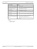
Check the loop OK LED indication (3) and connection fault LED indication (4) on the rear
panel of the Master Unit:
–
If the loop OK LED (3) is on, the connection is correct.
–
If the connection fault LED (4) is on, the polarity is incorrect in the last segment.
–
If both are not lit, there is a short or open circuit in the last segment.
10. Set the Walk Test mode to off.
Notice!
During installation, the Master Unit will correctly display a fault in the loop until the loop has
been installed correctly. When the entire loop has been installed correctly, the fault LED will
switch off within the fault recovery time.
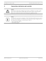
6.4
Loudspeakers Line Isolator System
Connections indicators and controls | en
39
Bosch Security Systems B.V.
Installation and Operation Manual
2014.03 | V1.1 |


