


System description
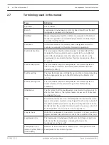
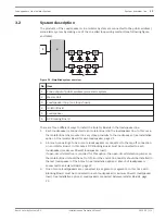
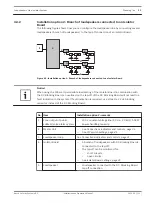
The products of the Loudspeakers Line Isolator System are connected to the public address/
voice alarm system by making use of the so-called loop wiring method (see following figure
and table):
1
2
3
4
6
6
5
5
4
4
4
4
4
3
Figure 3.1: Simplified system overview
No. Item
1
Zone output of public address/voice alarm system
2
Master Unit
3
Loudspeaker loop (one loop shown)
4
Isolator Board
5
Loudspeaker
6
DC Blocking Board
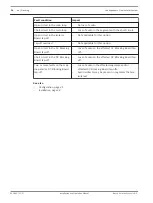
There are three different ways to install the Isolator Boards in the loudspeaker line:
1.
Each loudspeaker is connected to an Isolator Board in the loudspeaker line. In this case,
the Isolator Board is mounted in very close proximity to the loudspeaker. See Installation
option 1: One Isolator Board for each loudspeaker, page 21.
2.
A branch consisting of one or more loudspeakers is connected to the tap-off connection
on an Isolator Board. In this case a DC Blocking Board must be connected to each
loudspeaker (maximum 20 watt loudspeaker load).
If open-circuit detection is required for this option, the open-circuit detection jumper on
the Isolator Board should be set to ON, and the end-of-line resistor should be installed in
the last loudspeaker of the branch. See Installation option 2: Branch of loudspeakers
connected to an Isolator Board, page 23.
3.
One or more loudspeakers are connected in a segment or segments. In this case a DC
Blocking Board must be connected to each loudspeaker (maximum 20 watt loudspeaker
load). See Installation option 3: Loudspeakers connected between Isolator Boards, page
25.
3.2
Loudspeakers Line Isolator System
System overview | en
13
Bosch Security Systems B.V.
Installation and Operation Manual
2014.03 | V1.1 |


