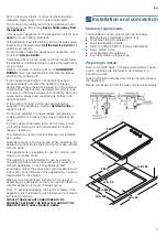
Bosch PBH6B5B60A User Instructions Installation Instructions Maintenance Instructions Download Page 5


en

5

Connection

Electrical

An electrical 10 amp socket needs to be within 1 m of 

the hotplate to allow electrical connection. The socket 

must remain accessible after installation of the 

appliance.

Important notes:

This appliance is connected to the mains (240 VAC) 

by means of the connecting lead which must be 

fixed to the kitchen unit to prevent it from coming 

into contact with hot parts of the cooktop (or an oven 

installed underneath) and remain accessible after 

installation of the cooktop.

When making this connection make sure that the 

lead cannot come into contact with hot parts of the 

cooktop.

This appliance must be earthed. When connecting 

the cooktop ensure that the earth wire is connected 

first and that all wires are connected to the correct 
terminals.

Gas

During the planning stage, consider the position of 

supply connections.
The cooktop must be connected to the gas supply with 

upstream connection of an isolation valve in 

accordance with the respectively valid regulations. We 

recommend that the isolation valve be fitted prior to the 

cooktop to enable isolation of cooktop from gas supply. 

The valve must be easily accessible at all times.
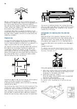
To find out the factory set gas type, see bottom of 

cooktop next to gas connection.
Remove plastic cap from gas supply line prior to 

installation.
Fit regulator (N.G.) or a test point (Universal LPG) 

directly to the R 1/2’’ connection.

Direction of gas flow is indicated on the rear of the 

regulator.
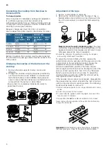
For position of the inlet connection refer 

Preparing to 

install

:

Use pipe compound or thread sealant, properly 

theaded pipes and careful assembly procedure so that 

there is no cross threading, etc., which might cause 

damage or leakage.
Make sure that all connections peformed are free of 

leakage. The manufacturer does not accept any liability 

for leakage on connections performed by the installer or 

if the L-tube is moved or twisted.
There are two ways to carry out the connection to the 

main gas line:

The hotplate can be connected with rigid pipe as 

specified in AS/NZS 5601.1

Flexible Hose: If installing with a hose assembly, it 

must comply with AS/NZS 1869, 10 mm ID, class B 

or D, no more than 1.2 m long and installed in 

accordance with AS/NZS 5601.1.

Ensure that the hose does not contact the hot 

surfaces of the hotplate, oven, dishwasher or any 

other appliance that may be installed underneath or 

next to the hotplate. The hose should not be 

subjected to abrasion, kinking or permanent 

deformation and should be able to be inspected 

along its entire length with the cooktop in the 

installed position. Unions compatible with the hose 

fittings must be used and all connections tested for 

gas leaks.

The supply connection point shall be accessible with the 

appliance installed.
WARNING: Ensure that the hose assembly is restrained 

from accidental contact with the flue outlet of an 

underbench oven.
To set the pressure (NG 1.0 kPa) operate the wok and 

auxiliary burners on full.
Before Leaving- Check all connections for gas leaks 

with soap and water. DO NOT use a naked flame for 

detecting leaks. Ignite all burners both individually and 

concurrently to ensure correct operation of gas valves, 

burners and ignition. Turn gas taps to low flame 

position and observe stability of the flame for each 

burner individually and all together. Adhere the 

duplicate data plate to an accessible location near the 

hotplate. When satisfied with the hotplate, please 

instruct the user on the correct method of operation. In 

case the appliance fails to operate correctly after all 

checks have been carried out, refer to the authorised 

service provider in your area.
It should be expressly noted that we cannot accept any 

liability for direct or indirect damage caused by wrong 

connection, leakage or improper installation. When 

being repaired, the appliance must always be 

disconnected from the mains supply; if required, notify 

our customer service.

/

9
9

1

99 a

Summary of Contents for PBH6B5B60A

Page 1: ...USER INSTRUCTIONS INSTALLATION INSTRUCTIONS MAINTENANCE INSTRUCTIONS 0 This cooktop is for use with Natural Gas and Universal LPG Leave this instructions with the owner PBH6B5B80A PBH6B5B60A PBH6B5B90A ...

Page 2: ...h do not use any phone in your building Inmediately call your gas supplier from a neighbour s phone Follow the gas supplier s instructions If you cannot reach your gas supplier call the fire department Installation and service must be performed by an authorised person Warnings Do not allow the flame to extend beyond the edge of the cooking utensil This instruction is based on safety considerations...

Page 3: ...e immediately for them to repair or replace it The illustrations used in this booklet are only intended as a guide Grids become very hot during use When operating the appliance control knobs take care not to make contact with the grids This appliance is not suitable for use in a marine craft caravan or mobile home This appliance is not intended for use by persons including children with reduced ph...

Page 4: ... be at least 10 mm from the lowest part of the hotplate and must be capable of withstanding the appliance temperatures Minimum thickness of benchtop is 30 mm After installation of the shield the clearance around the top and sides of shield will allow adequate ventilation Ensure the side and top clearances are not obstructed If an oven is positioned below the cooktop the barrier does not need to be...

Page 5: ...ler or if the L tube is moved or twisted There are two ways to carry out the connection to the main gas line The hotplate can be connected with rigid pipe as specified in AS NZS 5601 1 Flexible Hose If installing with a hose assembly it must comply with AS NZS 1869 10 mm ID class B or D no more than 1 2 m long and installed in accordance with AS NZS 5601 1 Ensure that the hose does not contact the...

Page 6: ...m liquids and dirt which might otherwise prevent its correct operation 3 Adjust the minimum ring setting by turning the by pass screw using a flat head screwdriver To adjust the minimum flame for N G replace the control knob onto the spindle light the gas and turn the control knob to the small flame position Screw the adjustment screw anti clockwise to estabilish a minimum stable flame position Th...

Page 7: ...ks Only when using cookware with a domed base on wok burners Additional support for espresso makers Only when using cookware with a base less than 12 cm in diam eter on the smallest burner Simmer Plate This accessory has been designed to reduce the level of heat at the lowest power setting Place the accessory directly on the pan support with the cones facing upwards never directly over the burner ...

Page 8: ...ut releasing the control knob press and hold it down firmly for 4 seconds after lighting the flame Switching off a burner Turn the corresponding control knob clockwise to the 0 setting Power levels The progressive control knobs can be used to control the power needed from minimum to maximum power Warnings It is normal to hear a soft whistling noise while the burner is operating When first used it ...

Page 9: ...g and keeping things hot cooked and pre cooked dishes Semi rapid burner Steamed potatoes fresh vegetables vegetable stews pasta Reheating keeping things hot and making tasty casseroles Auxiliary burner Cooking casse roles rice pudding caramel Defrosting and slow cooking vegetables fruit and fro zen products Melting but ter chocolate jelly Do not place anything eg flame tamer asbestos mat between p...

Page 10: ...ate correctly contact the authorised service provider in your area Fault Possible cause Solution The general electrical system is malfunctioning Defective fuse Check the fuse in the main fuse box and change it if it is damaged The automatic safety switch or circuit breaker has tripped Check the main control panel to see if the automatic safety switch or circuit breaker has tripped The automatic sw...

Page 11: ...en 11 Wiring diagram A Switch B Blue wire C Brown wire D Terminal E Ignition module ...

Page 12: ...3PCFSU PTDI BVTHFSÉUF NC XXX CPTDI IPNF DPN BSM 8FSZ 4USB F ßODIFO FSNBOZ 9001044070 9001044070 970823 C ...

Reviews: